An improved stable Ti/Sb–SnO2 electrode with high performance in electrochemical oxidation processes

Dan Shaoab, Xiaoliang Lib, Hao Xu*b and Wei Yan*ab
aState Key Laboratory of Multiphase Flow in Power Engineering, Xi'an Jiaotong University, Xi'an 710049, China
bDepartment of Environmental Science and Engineering, Xi'an Jiaotong University, Xi'an 710049, China. E-mail: xuhao@mail.xjtu.edu.cn; yanwei@mail.xjtu.edu.cn

Received 7th March 2014 , Accepted 14th April 2014

First published on 14th April 2014


Abstract

An improved Ti/Sb–SnO2 electrode was fabricated by inserting a specific Sb–SnO2 interlayer between the Ti substrate and the surface Sb–SnO2 coating. Characterization experiments including scanning electron microscopy (SEM), X-ray diffraction (XRD), energy dispersing spectrum (EDS), accelerated lifetime test, degradation experiment of an azo dye Acid Red G, and cyclic voltammetry (CV) measurement were performed to determine the effect of the interlayer. The results show that the coating on this new electrode is compact and crack-free. The distribution of Sn and Sb elements in the coating exhibits a gradient distribution from the bottom to the top. The high electrochemical oxidation capability of Ti/Sb–SnO2 did not decrease with the insertion of the interlayer. The improved electrode exhibited much higher electrode stability than the conventional Ti/SnO2 electrode. In a 0.5 M H2SO4 solution, at a current density of 200 mA cm−2, the accelerated lifetime of the conventional Ti/Sb–SnO2 was only 0.84 h, which is much lower that of the improved electrode (10.71 h). A possible reason for the electrode stability enhancement is attributed to the change in the electrode deactivation mechanism. In addition, practical service lifetimes were also estimated for the improved Ti/Sb–SnO2 in different media.

1 Introduction

Electrochemical (EC) oxidation processes of wastewater are attractive due to their simplicity, low energy consumption and environmental friendliness.1–3 The desired electrode material must fulfill four requirements, including long lifetime, high catalytic activity, low cost and no secondary pollution.4–8 Dimensionally stable anodes (DSAs) have received much attention due to the advantages of high electric catalytic activity, low cost, and simple preparation methods, among others. Generally, titanium is used as the substrate, and the primary chemical composition of the coating is a transition metal oxide such as RuO2, IrO2, TiO2, SnO2, PbO2, MnO2 and Ta2O5.9–15 Among these DSA materials, antimony-doped tin dioxide (Ti/Sb–SnO2) is regarded as one of the most promising anode materials for EC oxidation process due to its relatively high oxygen evolution potential (OEP), high EC oxidation activity, low cost and low toxicity.16–18

However, the main issue with Ti/Sb–SnO2 electrodes is their short lifetime, which severely limits further application. It is important to enhance the lifetime of Ti/Sb–SnO2 electrode significantly without decreasing the EC oxidation performance. The operational complexity and potential application value of the improved approach should also be considered.

Many researchers have devoted themselves to this challenging work. Interlayer insertion, ion-doping, and modification of Ti substrate are the three main approaches. However, the above three approaches are still not perfect. Interlayer insertion (using RuO2, IrO2, etc.) and noble ion-doping could increase the electrode stability significantly. However, due to the significant modification of the catalytic layer, the EC oxidation ability of the electrode is inevitably decreased and the cost of electrode material is increased.19,20 The modification of Ti substrate is another effective technique. For example, the formation of uniform TiO2 nanotube arrays by anodic oxidation is a representative technique.21,22 Sb–SnO2 could be filled into the TiO2 nanotubes (TiO2-NTs) that cover the Ti substrate. According to published reports (Zhao et al.23,24), the accelerated lifetime of such electrode (Ti/TiO2-NTs/Sb–SnO2) at a current density of 100 mA cm−2 was 36 h in 0.1 M H2SO4 and 42 h in 0.1 M Na2SO4, which is much higher than that of the conventional Ti/Sb–SnO2 (3 h in H2SO4 and 22 h in Na2SO4). However the fabrication of this electrode using the novel technique is not easy to reproduce. So far, it could only be realized on a laboratory-scale.

In this study, we attempted to find a simple and effective approach to enhance the lifetime of Ti/Sb–SnO2. An interlayer (Sb–SnO2) was inserted between the Ti substrate and the surface Sb–SnO2 coating via an electrodeposition-annealing process, whereas the outer Sb–SnO2 layer was coated using a conventional brush coating-pyrolysis method. To confirm the superiority of this improved electrode, a conventional Ti/Sb–SnO2 electrode prepared via brush coating-pyrolysis was fabricated as a control. The improved electrode is expected to exhibit much higher stability and unmodified catalytic activity in comparison with the conventional electrode.

2 Experimental

2.1 Electrode preparation

All chemical reagents were of analytical grade. Deionized water (18 MΩ cm) was obtained from an EPED-40TF water purification laboratory system (Yipuyida Technology development Ltd., Nanjing, China). A titanium plate (40 mm × 10 mm × 0.5 mm, >99.6 purity, BaoTi Co. Ltd, China) was used as the substrate. The substrate surface was first polished and etched as reported previously.25 The conventional Ti/Sb–SnO2 electrode was prepared using the brush coating-pyrolysis method (without an interlayer). The precursor for the brush coating was a solution mixture of isopropanol and n-butanol containing 0.5 M SnCl4, 0.02 M SbCl3, 0.1 M HNO3 and 0.001 M NaF. After brush coating, the sample was dried in an oven at 373 K for 5 min. Subsequently, the pyrolysis process was performed in a muffle furnace at 773 K for 15 min. The number of repeated brush coating-pyrolysis treatments was ∼20 for this electrode.

To fabricate the improved electrode, a mixture of Sn and Sb was first electrodeposited on a pretreated Ti substrate. The electrodeposition was performed in an ethanediol (glycol) solution containing 1 M SnCl4, 0.2 M SbCl3 and 0.1 M HNO3 at a working current density of 15 mA cm−2 for 10 min with graphite anodes as the counter electrodes. After electrodeposition, the electrode was heated in an oven at 773 K for 30 min and then cooled in air. When the interlayer was loaded, the surface layer was prepared by the same brush coating-pyrolysis method as discussed earlier. The number of repeated brush-pyrolysis treatments for this electrode was 10. The loading amount of coating for both electrodes was controlled at ∼3 mg cm−2.

2.2 Characterizations

The micromorphology and the elemental composition of the coating were characterized by a field-emission scanning electron microscope (FE-SEM: JSM-6700F, JEOL, Japan) equipped with an EDS (energy-dispersive X-ray spectroscopy) detector. The crystal structure of the coating was examined by X-ray diffraction (XRD, X'pert PRO MRD, Cu-Kα, PANalytical, Holland). In addition, a scanning electron microscope with EDS (SEM: JSM-6390A, JEOL, Japan) was used to characterize the deactivated electrode.

2.3 Electrochemical measurements

The accelerated lifetime tests were used to assess the stability of the electrode. A 0.5 M H2SO4 solution (1 L) was used as the electrolyte. The as-synthesized electrode (effective exposed area of 2 cm2) served as the working electrode and two copper plates of the same size were employed as the counter electrode. A potentiostat/galvanostat (LK 3000A, Lanlike, China) was used to provide a constant anodic current density of 200 mA cm−2. The working electrode was considered deactivated when the cell voltage reached to 10 V. To measure the electrode catalytic ability, the cyclic voltammetry test was performed using an electrochemical workstation (CHI 660D, Shanghai Chenhua, China) in a conventional three-electrode cell. The as-synthesized electrode (effective exposed area of 2 cm2) served as the working electrode and two copper plates of the same size were employed as the counter electrode. The Ag/AgCl electrode was chosen as the reference electrode.

Acid Red G (ARG, CAS no. 3734-67-6, analytical pure) was used as the target pollutant for degradation. The current efficiency is used to assess the catalytic oxidizing ability of the electrode. According to Faraday's law, the current efficiency is defined as the ratio between the theoretical quantity of electric charge and the actual quantity of electric charge that goes through the device. The theoretical quantity of electric charge is calculated by the measured COD removal. High current efficiency means high oxidizing ability of the electrode and high inhibition of side oxygen evolution reactions. The (electric) energy consumption is another index to assess the catalytic ability of the electrode. High energy consumption (kW h per g COD) means low utilization of electric energy upon organic degradation.

3 Results and discussion

3.1 SEM images

Generally, there are several essential annealing procedures involved in the DSA preparation process. Due to solvent volatilization and cold shrink problems, the surface of DSA electrodes inevitably exhibit a specific “crack-mud” micromorphology that has been described in many reports.1,3,6,10 Similarly, in our research, the surface morphology of Ti/Sb–SnO2 electrodes prepared by the conventional brush coating-pyrolysis method is porous with numerous deep and wide cracks (Fig. 1d).
image file: c4ra01990c-f1.tif
Fig. 1 (a) Interlayer of the improved Ti/Sb–SnO2 electrode (×500), (b) interlayer of the improved Ti/Sb–SnO2 electrode (×10[thin space (1/6-em)]000), (c) surface layer of the improved Ti/Sb–SnO2 electrode (×5000), (d) surface layer of the conventional Ti/Sb–SnO2 electrode with a typical “crack-mud” structure (×5000).

The introduction of an interlayer could inhibit the formation of such a “crack-mud” structure. The interlayer shows a porous, rough (Fig. 1a), and compact surface (Fig. 1b). We conceive that the interlayer formed a “rough substructure”, which may favor the adhesion of the top layer. As anticipated, the surface oxide layer of the novel electrode is compact and crack-free (Fig. 1c). In conclusion, despite using the same coating methods (brush coating-pyrolysis), the interlayer resulted in an improved electrode with a different surface micromorphology compared with the “mud-crack” structure of the conventional electrode (Fig. 1d).

The underlying reason for the difference in the surface morphology of the two electrodes may be complicated. But in consideration of the crack-free interlayer, a simplified interpretation is proposed below. The elemental compositions of the interlayer and the surface Sb–SnO2 layer are the same (Sn, Sb and O), so the thermal expansion coefficients of the two layers are similar. Further, the subsequent repeated brush coating-pyrolysis procedures (repeated heating–cooling processes) do not cause the cracking of the top Sb–SnO2 layer.

3.2 XRD And EDS analysis

The XRD spectra of the two types of Ti/Sb–SnO2 electrodes are illustrated in Fig. 2. Two strong characteristic diffraction peaks of the Ti substrate were detected in the XRD spectrum of the conventional Ti/Sb–SnO2 electrode (Fig. 2a). The Ti substrate was not completely covered by the coating although the loading amount of coating was sufficient; this may due to the wide and deep cracks in the body of the coating.
image file: c4ra01990c-f2.tif
Fig. 2 XRD spectra of the conventional Ti/Sb–SnO2 (a) and layers of the improved Ti/Sb–SnO2 (b) (1-interlayer); 2-surface layer (brush coating-pyrolysis 5 treatments); 3-surface layer (brush coating-pyrolysis 10 treatments).

Fig. 2b shows the variation in the XRD patterns of the improved electrode with the number of outside brush coating-pyrolysis treatments. The interlayer is a mixed phase of SnO2 and Sb2O4. When the brush-coating pyrolysis was performed repeatedly, the intensities of tin oxide characteristic diffraction peaks increased whereas those of the antimony oxide decreased gradually. No Sb was detected on the surface perhaps due to the low doping level or the incorporation of Sb in the SnO2 unit cell.26 Finally, on the surface of the novel electrode, a unique SnO2 phase (ICDD 01-077-0452) and no titanium were detected, indicating that the coverage of the Ti substrate was good.

The results of the EDS analysis show that the molar ratio of Sn and Sb is 100[thin space (1/6-em)]:[thin space (1/6-em)]28.25 in the interlayer and 100[thin space (1/6-em)]:[thin space (1/6-em)]11.05 in the surface layer. These results indicate that the high concentration of Sb decreases gradually from the bottom (interlayer) to the top (surface layer), which is in accordance with the XRD spectra. This gradient distribution of the elements (from the bottom to top) may enhance the combination of oxides in the coating and decrease the thermal stress between the coating and the Ti substrate. Moreover, the crack-free surface morphology of the improved electrode (Fig. 1c) may also be caused by this gradient distribution of Sn and Sb, which may eliminate inner stresses in the coating. The above two inferences are supported by some reports.27,28

3.3 Electrochemical oxidation ability

As discussed in the Introduction, the electrode stability should not be improved at the expense of the electrode oxidation ability. The electrochemical characterization of the improved Ti/Sb–SnO2 electrode was performed to examine the effect of the inserted interlayer on the EC oxidation capability of the electrode. The oxygen evolution potential (OEP) could be used to assess the EC oxidation ability. A more positive OEP indicates more inhibition of side reactions (including the oxygen evolution reaction), such that good oxidation ability could be reflected by a high OEP.7–10 From the cyclic voltammogram (CV) curves (Fig. 3), we observe that the OEP of the improved Ti/Sb–SnO2 electrode is greater than ∼2.2 V (vs. Ag/AgCl), which is similar to that of the conventional electrode (the determination of the OEP is illustrated in ESI Fig. S1). The introduction of the intermediate layer does not decrease the OEP. In addition, the response anodic current density could reach 0.07 A cm−2 at 2.5 V (vs. Ag/AgCl) for the improved electrode, which is even higher than that of the conventional electrode. In conclusion, the introduction of the interlayer does not decrease the oxidation ability and catalytic activity of the Ti/Sb–SnO2 electrode. With the exception of Sn, Sb and O elements, no additional elements (especially noble metal ions) were introduced in the interlayer to improve the electrode stability, which may be the reason why the high oxidation ability of the electrode is maintained.
image file: c4ra01990c-f3.tif
Fig. 3 Cyclic voltammogram curves of the conventional Ti/Sb–SnO2 and improved Ti/Sb–SnO2 (0.5 M H2SO4, electrode area of 2 cm2, and scan rate of 0.05 V s−1).

3.4 Electrode stability

To ensure the best and most durable performance, sufficient electrode stability is necessary. Fig. 4 shows the plots of current efficiency and energy consumption versus time for the oxidation of Acid Red G (ARG) by the conventional and improved Ti/Sb–SnO2 electrodes. The initial current efficiencies of the ARG removal for these two electrodes are similar (73.1% and 71.8% respectively). However, under practical conditions, the lifetime of the conventional electrode is only 6 days because of the continuous loss in electrode conductivity. At the end, the power supply could not afford the extra high cell voltage to maintain the current constant. This deactivation process could also be reflected in the rise of energy consumption from an initial value of 0.046 kW h per g COD to 0.157 kW h per g COD. The value of the energy consumption gradually becomes diseconomic. In contrast, the improved electrode maintains its performance as much as possible over a much longer period of time (more than 50 days) in terms of energy consumption and current efficiency.
image file: c4ra01990c-f4.tif
Fig. 4 Current efficiency and energy consumption versus time for the electrochemical oxidation of Acid Red G using the conventional Ti/Sb–SnO2 (lifetime: only 6 days) and improved Ti/Sb–SnO2 electrodes (lifetime: more than 50 days) (experimental conditions: constant anodic current density of 10 mA cm−2, ARG concentration of 2000 ppm, solution volume of 1 L, and room temperature).

To shorten the test time, the accelerated lifetime test is a good method for evaluating the whole service lifetime of the electrodes. The result of the accelerated lifetime test (Fig. 5) shows that the accelerated lifetime of the improved Ti/Sb–SnO2 electrode reaches ∼10.71 h, which is approximately 12 times higher than that of the traditional Ti/Sb–SnO2 electrode (∼0.84 h). Particularly, a platform of cell voltage (∼7 V) is observed in the curves. This cell voltage platform may correspond to the time that the electrolyte is in contact with the inner solid solution layer. In fact, the solid solution layer is a transitional layer between the Ti substrate and the outer coating that is formed during the heating procedure in the fabrication process. A longer platform duration may mean a stronger resistance of the solid solution layer against corrosion and electrolyte penetration. The duration time of such a cell voltage platform in the traditional Ti/Sb–SnO2 electrode is only ∼0.25 h, which is much lower than that of the improved electrode (∼2.5 h). Therefore, the interlayer may benefit from the formation of a solid solution layer (due to improved compactness).


image file: c4ra01990c-f5.tif
Fig. 5 Accelerated lifetime test curves of the conventional Ti/Sb–SnO2 and improved Ti/Sb–SnO2 (room temperature, 0.5 M H2SO4, anodic current density of 200 mA cm−2, and electrode area of 2 cm2).

In addition, compared with the reported accelerated lifetimes of various Ti based Sb–SnO2 electrodes (listed in Table 1), the improved Ti/Sb–SnO2 electrode developed in this study has adequate stability under similar test conditions. It should be noted that in 0.5 M H2SO4, when the current density decreased to half its value, the accelerated lifetime of the improved electrode was 38.32 h. The effect of the current density and electrolyte on the electrode lifetime will be discussed later.

Table 1 Accelerated lifetime data for Ti based Sb–SnO2 electrode in some recent reports
Anode name Electrolyte Anodic current density Accelerated lifetime Ref.
Ti/Sb–SnO2 0.5 M NaOH <=200 mA cm−2 12 h 20
Ti/TiO2-NTs/Sb–SnO2 0.1 M H2SO4 100 mA cm−2 36 h 23
Ti/TiO2-NTs/Sb–SnO2 0.1 M Na2SO4 100 mA cm−2 42 h 24
Ti/Sb–SnO2 0.5 M H2SO4 100 mA cm−2 12.1 h 29
Ti/SnO2–Sb–Bi 0.5 M H2SO4 100 mA cm−2 0.8 h 30
Ti/SnO2–Sb2O4-CNT-Cr3C2 1 M H2SO4 100 mA cm−2 7 h 31
The improved Ti/Sb–SnO2 0.5 M H2SO4 200 mA cm−2 10.71 h This work
The improved Ti/Sb–SnO2 0.5 M H2SO4 100 mA cm−2 38.32 h This work


3.5 Deactivation mechanism

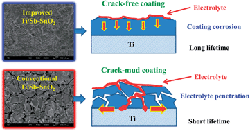
Based on the above results and discussions, it appears that the introduction of an interlayer may change the deactivation mechanism of the Ti/Sb–SnO2 electrode. In the case of the conventional Ti/Sb–SnO2 electrode, the coating is loaded on the substrate layer by layer, so an unavoidable defect (numerous cracks in the body of the coating, not only on the surface) may result in fast electrode deactivation according to the following process. First, the electrolyte could penetrate into the coating through the cracks. The Ti is then oxidized when the electrolyte finally reaches the Ti substrate. Subsequently, the nonconductive TiO2 would form and spread along this the interface between the Ti substrate and the oxide coating. Second, the generated oxygen bubbles in the micro cracks of the coating cannot diffuse away from the cracks in a timely and effective manner. Thus, the gas bubbles lead to high gas stresses that may strike the coating continuously and result in the stripping of the coating. Finally, the Ti substrate can become oxidized more easily without effective protection. These possible explanations are supported by many reports.32–34

However, as for the improved Ti/Sb–SnO2 electrode, the interlayer is loaded on the substrate by a single heating-cooling process (“one-time approach”). Therefore, no inherent cracks exist in the body of the interlayer. The interlayer could be regarded as a buffer layer between the Ti substrate and the surface coating. The interfacial stress between the coating and substrate and the inner stress in the coating may be decreased by this interlayer. The surface layer does not have obvious cracks, which may be caused by the above reasons. The compact and crack-free coating provides excellent protection against electrolyte penetration to the underlying layer. The issue of mechanical corrosion by bubbles is also minimized.

The difference in the lifetimes of the improved and conventional electrodes may be caused by the difference in the deactivation mechanisms. Fig. 6 illustrates the deactivation mechanisms of the conventional and improved Ti/Sb–SnO2 electrodes. It is widely reported that the final step of the deactivation process is the formation of a non-conductive TiO2 layer on the Ti substrate. The formation and spread of such a TiO2 layer on the substrate-coating interface is fast. In comparison with electrolyte penetration, the wear of the coating is more “time consuming”. The delay of the electrolyte penetration is a key mechanism in the lifetime enhancement for the improved electrode. Therefore, it can be inferred that a considerable amount of coating may be present on the deactivated conventional Ti/Sb–SnO2 electrode, which is significantly more than that observed on the deactivated improved Ti/Sb–SnO2 electrode.


image file: c4ra01990c-f6.tif
Fig. 6 Deactivation mechanisms of the conventional Ti/Sb–SnO2 electrode (rate controlling step: electrolyte penetration) and the improved Ti/Sb–SnO2 electrode (rate controlling step: wear of the coating).

The results from the EDS and SEM analysis on the deactivated electrodes (Fig. 7 and ESI Fig. S2) could also confirm the above inferences. The atom% of Ti on the deactivated conventional electrode is only 0.86%, whereas those of Sn and Sb are 14.72% and 7.55% respectively, which indicates that the Ti substrate is still covered by a considerable amount of coating. In addition, the high atom% of sulfur (15.81%) indicates that a lot of corrosion products (sulfates) cover the residual Sb–SnO2 coating. The SEM image (inset in Fig. 7a) of the deactivated conventional electrode also retains the crack-mud structure.


image file: c4ra01990c-f7.tif
Fig. 7 Surface elemental analysis and SEM images (shown as the inset) of the deactivated conventional Ti/Sb–SnO2 (a) and the deactivated improved Ti/Sb–SnO2 (b) after the accelerated lifetime test (0.5 M H2SO4, solution volume of 1 L, anodic current density of 200 mA cm−2, and room temperature).

In contrast, the atom% of Ti in the deactivated improved electrode is 25.74%, while that of Sn and Sb are 6.35% and 3.72% respectively, which indicates an obvious loss of the coating and the exposure of the Ti substrate. The atom% of sulfur is only 3.13%, so even the corrosion products are few in number. The SEM image of the deactivated improved electrode shows a crack-free structure (inset of Fig. 7b), which may indicate that the coating of the improved electrode may be crack-free from the bottom to the top.

3.6 Practical electrolysis on improved Ti/Sb–SnO2 electrode

Generally, the anodic current density applied to Ti/Sb–SnO2 electrodes in practical electrochemical oxidation processes is much lower than that of the accelerated lifetime experiments. Different electrolytes also strongly affect the electrode stability. Therefore, it is worth calculating the actual service lifetime from the relationship between current density and service lifetimes in different media. The lifetimes of the improved Ti/Sb–SnO2 in different media (NaOH, Na2SO4, H2SO4 and NaCl) and under a series of anodic current densities (50, 100, 200, 500, 1000 mA cm−2) are shown in Fig. 8. It was found that a higher current density does more harm to the electrode stability. In fact, a higher current density causes an increase in the acidity around the anode-solution interface and a higher evolution rate of oxygen bubbles:
 
2H2O − 2e → 2H+ + O2↑ (acid medium) (1)
 
4OH − 4e → O2↑ + 2H2O (neutral and alkaline media) (2)

image file: c4ra01990c-f8.tif
Fig. 8 Average service lifetimes of the improved Ti/Sb–SnO2 at different anodic current densities in different media (the inset is the magnification of the data between 50 and 500 mA cm−2).

The high acidity may accelerate the coating dissolution rate. High evolution rate of bubbles could intensify the rate of mechanical loss of the coating. In Fig. 8, under the same current density, the sequence of service livetimes in different media (in NaOH > Na2SO4 > H2SO4 > NaCl) indicates that the Ti/Sb–SnO2 electrode is more stable in an alkali rather than an acidic medium. The presence of the chloride ion is undesirable during the service of the Ti/Sb–SnO2 electrode, which may also accelerate the coating dissolution rate because of the strong corrosion ability of chlorine. Due to the much lower current density used under normal operating conditions, the real service lifetimes of the electrode will be much longer than the lifetime obtained during the accelerated lifetime test. According to some studies,35–37 there is a simple relationship between the electrode service lifetime (L) and the current density (i):

 
image file: c4ra01990c-t1.tif(3)
where n is the power value and K is a coefficient. For each electrolyte, according to eqn (3) and Fig. 8, the electrode service lifetime is inversely proportional to the specific power function of the current density. Therefore, for each electrolyte, the service life of the electrode under a certain current density could be estimated by fitting the data in Fig. 8. A series of estimated practical service livetimes of improved Ti/Sb–SnO2 (at low current densities) are provided in Table 2. Different n values in different media, which indicate the influence of the electrolyte, are also provided. For example, in NaOH, the n value is 1.72 (the highest), which indicates the effect of current density is more obvious in this electrolyte. In NaCl, the n value is 1.22 (the lowest), which indicates that this electrolyte results in the worst performance

Table 2 Estimated service lifetimes of the improved Ti/Sb–SnO2 under different conditions
Electrolyte n value Service lifetime (10 mA cm−2) Service lifetime (20 mA cm−2)
NaOH (1 M) 1.72 13.43 years 4.08 years
Na2SO4 (0.1 M) 1.35 1.77 years 0.69 years
H2SO4 (0.5 M) 1.30 224.48 days 91.17 days
NaCl (0.1 M) 1.22 140.17 days 60.17 days


In spite of the relative low stability of the system in NaCl, the improved electrode could exhibit normal operational performance for a few months to several years. Because the electrode material is low cost and the preparation method is simple, the improved Ti/Sb–SnO2 electrode could be applied in industry.

4 Conclusions

The lifetime of the improved Ti/Sb–SnO2 electrode (with a Sb–SnO2 interlayer) is approximately 20 times longer than that of the conventional Ti/Sb–SnO2 electrode. The surface of improved electrode does not exhibit the typical crack-mud structure that is observed with the conventional electrode. More importantly, the introduction of the interlayer does not decrease the electrochemical oxidation ability of the Ti/Sb–SnO2 electrode because no additional element is added to the coating. The extension of the electrode lifetime (compared with the conventional electrode) may be mainly ascribed to the stronger resistance to electrolyte penetration and mechanical wear caused by bubble evolution. Experiments on the performance of electrodes at different anodic current densities and in different electrolytes show that the improved Ti/Sb–SnO2 electrode could be applied practically.

Acknowledgements

This work was supported by the National Natural Science Foundation of China (Grant no. 21307098) and Fundamental Research Funds for the Central Universities of China.

References

  1. C. A. M. Huitle and S. Ferro, Electrochemical oxidation of organic pollutants for the wastewater treatment: direct and indirect processes, Chem. Soc. Rev., 2006, 35, 1324–1340 RSC .
  2. B. Ntsendwana, B. B. Mamba, S. Sampath and O. A. Arotiba, Synthesis, characterisation and application of an exfoliated graphite–diamond composite electrode in the electrochemical degradation of trichloroethylene, RSC Adv., 2013, 3, 24473–24483 RSC .
  3. M. Panizza and G. Cerisola, Direct and mediated anodic oxidation of organic pollutants, Chem. Rev., 2009, 109, 6541–6569 CrossRef CAS PubMed .
  4. S. Trasatti, Electrocatalysis: understanding the success of DSA®, Electrochim. Acta, 2000, 45, 2377–2385 CrossRef CAS .
  5. A. S. Bandarenka, E. Ventosa, A. Maljusch, J. Masa and W. Schuhmann, Techniques and methodologies in modern electrocatalysis: evaluation of activity, selectivity and stability of catalytic materials, Analyst, 2014, 139, 1274–1291 RSC .
  6. G. H. Chen, Electrochemical technologies in wastewater treatment, Sep. Purif. Technol., 2004, 38, 11–41 CrossRef CAS PubMed .
  7. Y. J. Feng and X. Y. Li, Electrocatalytic oxidation of phenol on several metal-oxide electrodes in aqueous solution, Water Res., 2003, 37, 2399–2407 CrossRef CAS .
  8. A. Dominguez-Ramos, R. Aldaco and A. Irabien, Electrochemical oxidation of lignosulphonate: total organic carbon oxidation kinetics, Ind. Eng. Chem. Res., 2008, 47, 9848–9853 CrossRef CAS .
  9. G. H. Zhao, Y. G. Zhang, Y. Z. Lei, B. Y. Lv, J. X. Gao, Y. N. Zhang and D. M. Li, Fabrication and electrochemical treatment application of a novel lead dioxide anode with superhydrophobic surfaces, high oxygen evolution potential, and oxidation capability, Environ. Sci. Technol., 2010, 44, 1754–1759 CrossRef CAS PubMed .
  10. Y. H. Cui, Y. J. Feng and Z. Q. Liu, Influence of rare earths doping on the structure and electro-catalytic performance of Ti/Sb–SnO2 electrodes, Electrochim. Acta, 2009, 54, 4903–4909 CrossRef CAS PubMed .
  11. S. Y. Chen, Y. H. Zheng, S. W. Wang and X. M. Chen, Ti/RuO2–Sb2O5–SnO2 electrodes for chlorine evolution from seawater, Chem. Eng. J., 2011, 172, 47–51 CrossRef CAS PubMed .
  12. F. Cardarelli, P. Taxil and A. Savall, Preparation of oxygen evolving electrodes with long service life under extreme conditions, J. Appl. Electrochem., 1998, 28, 245–250 CrossRef CAS .
  13. R. Tolba, M. Tian, J. L. Wen, Z. H. Jiang and A. C. Chen, Electrochemical oxidation of lignin at IrO2-based oxide electrodes, J. Electroanal. Chem., 2010, 649, 9–15 CrossRef CAS PubMed .
  14. G. F. Pereira, R. C. Rocha-Filho, N. Bocchi and S. R. Biaggio, Electrochemical degradation of bisphenol A using a flow reactor with a boron-doped diamond anode, Chem. Eng. J., 2012, 198-199, 282–288 CrossRef CAS PubMed .
  15. J. Y. Xu, M. Wang, G. Y. Liu, J. L. Li and X. D. Wang, The physical-chemical properties and electrocatalytic performance of iridium oxide in oxygen evolution, Electrochim. Acta, 2011, 56, 10223–10230 CrossRef PubMed .
  16. S. Stucki, R. Kötz, B. Carcer and W. Suter, Electrochemical waste water treatment using high overvoltage anodes. Part II: anode performance and applications, J. Appl. Electrochem., 1991, 21, 99–104 CrossRef CAS .
  17. Ch. Comnellis, Electrocatalysis in the electrochemical conversion/combustion of organic pollutants for wastewater treatment, Electrochim. Acta, 1994, 39, 1857–1862 CrossRef .
  18. D. Shao, J. D. Liang, X. M. Cui, H. Xu and W. Yan, Electrochemical oxidation of lignin by two typical electrodes: Ti/Sb–SnO2 and Ti/PbO2, Chem. Eng. J., 2014, 244, 288–295 CrossRef CAS PubMed .
  19. B. Correa-Lozano, C. Comninellis and A. De Battisti, Service life of Ti/SnO2–Sb2O5 anodes, J. Appl. Electrochem., 1997, 27, 970–974 CrossRef CAS .
  20. B. Adams, M. Tian and A. C. Chen, Design and electrochemical study of SnO2-based mixed oxide electrodes, Electrochim. Acta, 2009, 54, 1491–1498 CrossRef CAS PubMed .
  21. V. Galstyan, A. Vomiero, E. Comini, G. Faglia and G. Sberveglieri, TiO2 nanotubular and nanoporous arrays by electrochemical anodization on different substrates, RSC Adv., 2011, 1, 1038–1044 RSC .
  22. T. Wu, G. H. Zhao, Y. Z. Lei and P. Q. Li, Distinctive tin dioxide anode fabricated by pulse electrodeposition: High oxygen evolution potential and efficient electrochemical degradation of fluorobenzene, J. Phys. Chem. C, 2011, 115, 3888–3898 CAS .
  23. G. H. Zhao, X. Cui, M. C. Liu, P. Q. Li, Y. G. Zhang, T. C. Cao, H. X. Li, Y. Z. Lei, L. Liu and D. M. Li, Electrochemical degradation of refractory pollutant using a novel microstructured TiO2 nanotubes/Sb-doped SnO2 electrode, Environ. Sci. Technol., 2009, 43, 1480–1486 CrossRef CAS .
  24. X. Cui, G. H. Zhao, Y. Z. Lei, H. X. Li, P. Q. Li and M. C. Liu, Novel vertically aligned TiO2 nanotubes embedded with Sb-doped SnO2 electrode with high oxygen evolution potential and long service time, Mater. Chem. Phys., 2009, 13, 314–321 CrossRef PubMed .
  25. D. Shao, W. Yan, L. Cao, X. L. Li and H. Xu, High-performance Ti/Sb–SnO2/Pb3O4 electrodes for chlorine evolution: Preparation and characteristics, J. Hazard. Mater., 2014, 267, 238–244 CrossRef CAS PubMed .
  26. X. M. Chen, G. H. Chen and P. L. Yue, Stable Ti/IrOXSb2O5–SnO2 anode for O2 evolution with low Ir content, J. Phys. Chem. B, 2001, 105, 4623–4628 CrossRef CAS .
  27. C. A. A. Cairo, M. L. A. Graça, C. R. M. Silva and J. C. Bressiani, Functionally gradient ceramic coating for carbon–carbon antioxidation protection, J. Eur. Ceram. Soc., 2001, 21, 325–329 CrossRef CAS .
  28. L. Y. Zhang, Q. B. Liu, P. Z. Jiang and Z. Zhang, The microstructure of gradient composite bioceramic coating with single and multiple rare earth oxide fabricated by wide band laser cladding, Appl. Mech. Mater., 2013, 341, 171–174 Search PubMed .
  29. H. Y. Ding, Y. J. Feng and J. W. Lu, Study on the service life and deactivation mechanism of Ti/SnO2–Sb electrode by physical and electrochemical methods, Russ. J. Electrochem., 2010, 46, 72–76 CrossRef CAS .
  30. Q. F. Zhuo, S. B. Deng, B. Yang, J. Huang and G. Yu, Efficient electrochemical oxidation of perfluorooctanoate using a Ti/SnO2–Sb–Bi anode, Environ. Sci. Technol., 2011, 45, 2973–2979 CrossRef CAS PubMed .
  31. F. P. Hu, Z. Q. Dong, X. W. Cui and W. X. Chen, Improved SnO2–Sb2O4 based anode modified with Cr3C2 and CNT for phenol oxidation, Electrochim. Acta, 2011, 56, 1576–1580 CrossRef CAS PubMed .
  32. C. C. Jara, G. R. Salazar-Banda, R. S. Arratia, J. S. Campino and M. I. Aguilera, Improving the stability of Sb doped Sn oxides electrode thermally synthesized by using an acid ionic liquid as solvent, Chem. Eng. J., 2011, 171, 1253–1262 CrossRef PubMed .
  33. F. Vicent, E. Morallon, C. Quijada, J. L. Vazquez, A. Aldaz and F. Cases, Characterization and stability of doped SnO2 anodes, J. Appl. Electrochem., 1998, 28, 607–612 CrossRef CAS .
  34. L. K. Xu and J. D. Scantlebury, A study on the deactivation of an IrO2–Ta2O5 coated titanium anode, Corros. Sci., 2003, 45, 2729–2740 CrossRef CAS .
  35. B. Krishnamurthy, R. E. White and H. J. Ploehn, Electric field strength effects on time-dependent passivation of metal surfaces, Electrochim. Acta, 2002, 47, 2505–2513 CrossRef CAS .
  36. D. S. Kong, W. H. Lu, Y. Y. Feng, Z. Y. Yu, J. X. Wu, W. J. Fan and H. Y. Liu, Studying on the point-defect-conductive property of the semiconducting anodic oxide films on titanium corrosion, passivation, and anodic films, J. Electrochem. Soc., 2009, 156, 39–44 CrossRef PubMed .
  37. S. Y. Chen, Y. H. Zheng, S. W. Wang and X. M. Chen, Ti/RuO2–Sb2O5–SnO2 electrodes for chlorine evolution from seawater, Chem. Eng. J., 2011, 172, 47–51 CrossRef CAS PubMed .

Footnote

Electronic supplementary information (ESI) available. See DOI: 10.1039/c4ra01990c

This journal is © The Royal Society of Chemistry 2014
Click here to see how this site uses Cookies. View our privacy policy here.