 Open Access Article
 This Open Access Article is licensed under a
 Creative Commons Attribution 3.0 Unported Licence
Understanding the solar-driven reduction of CO2 on doped ceria†
Enrique V. Ramos-Fernandez*,
N. Raveendran Shiju* and
Gadi Rothenberg
Van't Hoff Institute for Molecular Sciences, University of Amsterdam, P.O. Box 94157, 1090 GD Amsterdam, The Netherlands. E-mail: enrique.ramos@ua.es; n.r.shiju@uva.nl; Web: http://hims.uva.nl/hcsc
First published on 2nd April 2014
Abstract
With the appropriate materials, one can construct redox cycles that use CO2 as the oxidant, generating CO as the product. Here, we investigate thermochemical cycles using doped ceria compounds as the oxygen exchange medium. Doped samples are prepared using La, Cr, W, Zr, V, Y, and Ti as dopants. Studying the redox kinetics, we show that doping the pure ceria with zirconium strongly increases overall CO production, albeit at lower reaction rates. This is because the CO2 reduction step is second-order with respect to Ce(III). Doping the fluorite lattice with zirconium cations decreases the number of Ce(III) ions at the surface, and consequently slows down the reaction. This result is counter-intuitive, since normally you would think that the more reduction, the better. But the reactivity towards CO2 is actually determined by the surface Ce(III) ions, and so migration of dopant ions on the surface reduces its reactivity, even though the bulk Ce(III) concentration is higher. Our results demonstrate the importance of understanding surface kinetics when designing oxygen exchange materials for solar reactors.
Introduction
Energy demand and greenhouse gas emissions are two of the main problems that our society faces today. In principle, both can be solved by converting CO2 to fuels using sunlight. Plants have been doing this for millions of years, albeit rather slowly. The challenge for us chemists is therefore finding ways for converting CO2 to fuels more quickly and efficiently.1One of the most promising ways to meet this challenge is using solar-driven high-temperature thermochemical cycles based on metal oxide redox reactions. Such cycles can split water and CO2, giving hydrogen and CO.2–4 This so-called syn-gas mixture can then be converted catalytically to conventional liquid fuels, using for example Fischer–Tropsch technology.1,5 Unlike direct thermolysis, these cycles avoid the CO/O2 and H2/O2 separation issues.
The problem is that the oxides used, typically ZnO and SnO2, are volatile.6,7 They sublime during decomposition, requiring rapid quenching of gaseous products to avoid recombination. Similarly, less volatile oxides such as ferrite-based ones suffer from slow kinetics, sintering, plus yet some material loss due to volatilization.8
One class of materials that avoids these problems is non-stoichiometric cerium oxides (doped ceria compounds). These materials combine several advantages: (i) cerium, with the electron configuration [Xe]4f15d16s2, has two stable valence states, Ce3+ and Ce4+, that are suitable for redox cycling;9–11 (ii) ceria crystallizes in the stable fluorite structure up to 2750 K,12,13 so they are unchanged over the entire reaction working range; (iii) the reduced and oxidised states have strikingly different colors (pale yellow and blue-black, respectively), so changes in the oxidation state are easily and visibly trackable;13 and (iv) doped ceria can accommodate high oxygen deficiencies by the substitution of elements on the cation sub-lattice. This gives high oxygen ion conductivities. Simultaneously, these materials can release significant levels of oxygen at low oxygen partial pressures and high temperatures. These two parameters are directly influenced by the type and amount of the dopant.14–19
That said, building efficient cycles using doped ceria is far from trivial. This is because efficiency is a combination of capacity (CO production per oxide mass) and speed (CO production per time). To reach high capacity at reasonable times, we must first understand and control the kinetics of this non-equilibrium system. Here we describe, for the first time, the factors governing the application of doped ceria as oxygen exchange reagents for thermocatalytic reduction of CO2 to CO. To help readers who are unfamiliar with surface kinetics models we include also a short theory section.
Theory
The rate of a solid-state reaction is described by,20–24
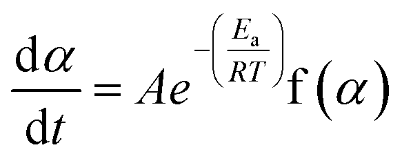 | (1) |
 | (2) |
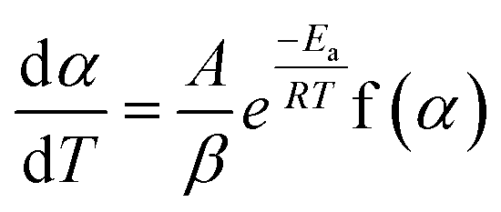 | (3) |
Separating variables and integrating eqn (1) and (3) gives the integral forms of the isothermal and non-isothermal rate laws, respectively, shown in eqn (4) and (5):
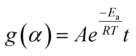 | (4) |
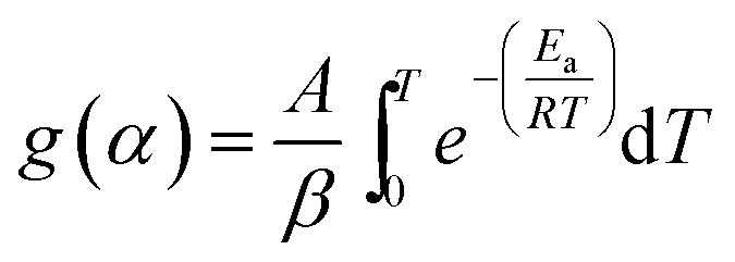 | (5) |
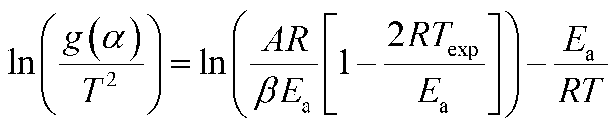
As eqn (5) has no analytical solution, we used the Coats–Redfern30 method to approximate the exponential integral by an asymptotic series expansion, giving eqn (6):
 | (6) |
Experimental section
Materials and instrumentation
Chemicals were purchased from Sigma-Aldrich and used as received. Gases were purchased from Praxair and had a purity of 99.95% or higher. Thermogravimetric analysis was performed using a Netzsch TGA instrument with three individual mass-flow controllers coupled to a quadruple mass spectrometer (see Fig. 1).Catalyst preparation
Catalysts were prepared using a modification of a previously published procedure,25 by co-melting a mixture of the metal nitrate hydrate precursors (chlorides or ammonium salts were used when nitrates were not available). After the precursor has liquefied, the pressure was lowered and a solid mixed-metal nitrate formed. This was converted into the mixed oxide by calcining in static air at 700 °C for 5 h. X-ray diffraction confirmed that all of the catalysts were monophasic, with a clear fluorite structure (see ESI for details†). Using the method described above, we prepared seven doped materials, using 10% wt La, Cr, W, Zr, V, Y, and Ti as dopants, as well as a sample with 30% wt Zr.General procedure for thermocatalytic redox cycling
A blank experiment was run before every measurement, using an empty crucible to correct the mass signal. This ensures we are measuring the redox kinetics of ceria, which is not influenced by TGA response function. About 100 mg of material was weighed in a platinum crucible and placed on the thermobalance. Then, residual air in the TGA chamber was replaced with argon, to operate in inert atmosphere and improve the reduction yield by decreasing the oxygen partial pressure (Fig. 1). The sample was heated in an argon flow and the mass variation was registered continuously (this mass variation can be directly correlated to the oxygen release during the reduction step or to the re-oxidation of the material during the CO2 splitting step). In a typical experiment, five successive cycles (reduction and reoxidation) were done. The reduction step consisted of heating the sample to 1400 °C at 10 °C min−1, and then maintaining this temperature for 1 h. The mass loss registered above 800 °C is directly correlated to the oxygen released from the oxide. Then, the temperature was lowered to 1100 °C for the second re-oxidation step, and CO2 was injected into the furnace chamber, reacting with the oxygen-deficient material and producing CO. The CO2 stream was injected from the auxiliary gas inlet and mixed with argon, the carrier gas (total flow rate 100 mL min−1; 50% CO2). Table 1 summarizes the experiments done.| Sample | Temperature of reduction, °C | Temperature of oxidation, °C | Number of cycles |
|---|---|---|---|
| CeO2 | 1400 | 1100 | 5 |
| Ce0.9M0.1O2, M = Zr, Y, V, Cr, W, La, Ti | 1400 | 1100 | 5 |
| CeO2 | 1400 | 1000, 900, 800, 700, 600 | 5 |
| Ce0.9Zr0.1O2 | 1400 | 1000, 900, 800, 700, 600 | 5 |
| Ce0.7Zr0.3O2 | 1400 | 1000, 900, 800, 700, 600 | 5 |
| CeO2 | 1000, 1100, 1200, 1300, 1400 | 1000 | 5 |
| Ce0.9Zr0.1O2 | 1000, 1100, 1200, 1300, 1400 | 1000 | 5 |
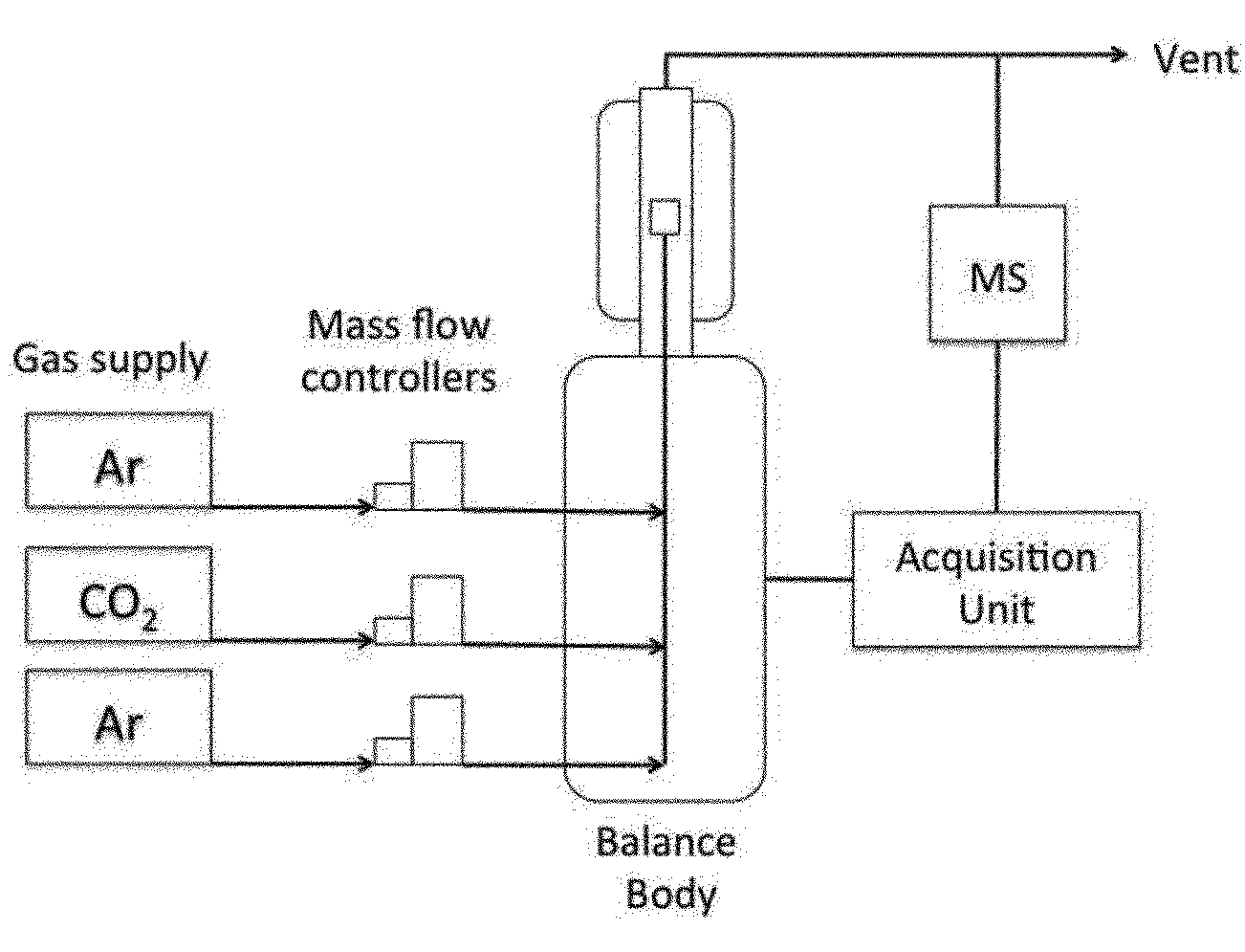 | ||
| Fig. 1 Schematic representation of the experimental set-up. | ||
Procedure for kinetic studies
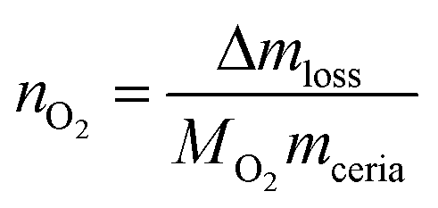
The above general procedure was modified as follows: (i) the reduction temperature was changed in between cycles ranging from 1000 °C to 1400 °C, while the oxidation step was kept constant at 1000 °C; (ii) the oxidation temperature was modified for the different cycles going from 1000 °C to 600 °C while the reduction temperature was kept at 1400 °C for all the cycles. The gas flows and concentrations were identical to those in the general procedure. Isothermal steps lasted for 1 h and the heating and cooling temperature was 10 °C min−1. The mass changes are converted to the moles of O2 released (reduction step) per gram of ceria or doped-ceria using eqn (7),
 | (7) |
The reduction level, %Ce(III) is then calculated using eqn (8),
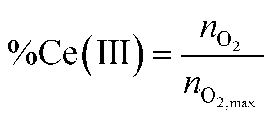 | (8) |
Taking into account that
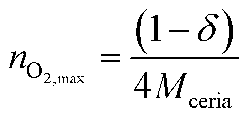 | (9) |
Results and discussion
Thermal reduction of doped ceria
From our previous work we know two important facts.16,17,19 First, that CeO2 can act as an oxygen exchange reagent for reducing CO2. Second, that we can change the rate and magnitude of the oxygen migration to and from the lattice by doping the pure ceria with up to 10–15% metal ions of similar charge and/or radius to those of Ce(IV), while keeping the fluorite lattice intact.2–4,27,28 We thus tested first a series of Ce0.9M0.1O2 (M = Zr, Y, V, Cr, W, La, Ti; see ESI for details†). Of these, only zirconium-doped ceria showed a significant increase of CO production. We focused therefore on this material. Fig. 2, top, shows a typical multi-cycle profile. We see that upon thermal treatment in inert conditions the Ce(IV) is gradually reduced to Ce(III). If we then decrease the temperature down to 1100 °C and feed CO2, the Ce(III) ions are immediately oxidized, giving CO and Ce(IV)O (eqn (10)). This cycle can be repeated at least five times without any loss of activity.
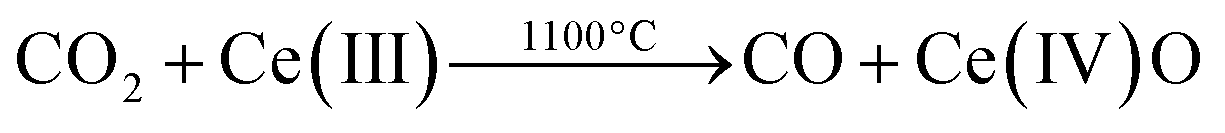 | (10) |
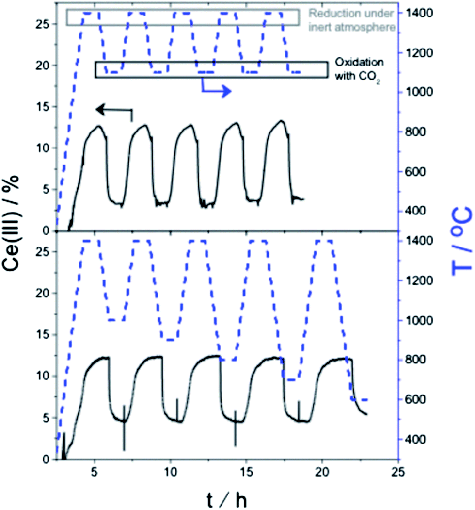 | ||
| Fig. 2 (Top) Isothermal oxidation (1100 °C) and reduction (1400 °C) step cycling using CO2 and argon, respectively for Ce0.9Zr0.1O2. The blue dotted curves give the temperature program, while the continuous lines show the Ce(III) concentration; (bottom) analogous experiments showing redox cycling at decreasing oxidation temperatures, from 1000 °C down to 600 °C. | ||
Following this, we repeated the redox cycles, but this time running the oxidation step at five different temperatures, from 1000 °C down to 600 °C. Even at 600 °C, CO2 was reduced to CO, reflecting the large energy penalty paid during the Ce(IV) reduction step. We also confirmed the exothermicity of the total reaction of CO2 reduction plus Ce(III) oxidation using differential scanning calorimetry.4,29
Kinetic analysis
Several studies reported CO2 reduction using ceria-doped materials.2–4,27,28 Most of these focus on the reduction step, aiming at high degrees of reduction. While this is an important goal, it must be matched with a high reaction rate. This is especially important for practical applications using solar energy, where continuous operation is preferable. The best way to work continuously is using a cylindrical rotor coated by a reactive oxide with two reaction zones, one for releasing oxygen and the other for reacting CO2 (see schematic in Fig. 3). Both reactions should have comparable rates for efficient continuous redox cycling.29–31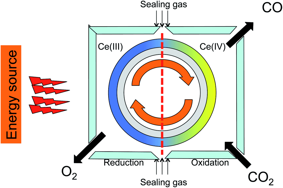 | ||
| Fig. 3 Cartoon showing a solar furnace with cylindrical rotor coated by reactive oxide and two reaction cells, one for oxygen releasing (left) and the other is for reducing CO2 to CO (right). | ||
To understand the reaction profiles shown in Fig. 2, we include also the derivation of the kinetic parameters of the ceria reduction and oxidation steps. We derived these from the thermogravimetric analysis at isothermal and non-isothermal conditions (see the Theory section).21,23
Kinetics of ceria and doped ceria reduction
We then fitted the experimental results to the most plausible kinetic models for solid-state reactions (17 models in total, details in the ESI†).21,23,32–38 Analysing the dynamic step (the ceria reduction step) we see that no single model fits the entire data set. Rather, we see two slopes. Fig. 4 shows, as an example, the Arrhenius plots for ceria and Ce0.9Zr0.1O2 following Jander's diffusion model (D3 model). Although this model gives the best linear fit, it still deviates from the data at low temperatures (below ca. 900 °C). This is because the activation energy changes as the temperature increases. In other words: there are two different mechanisms involved.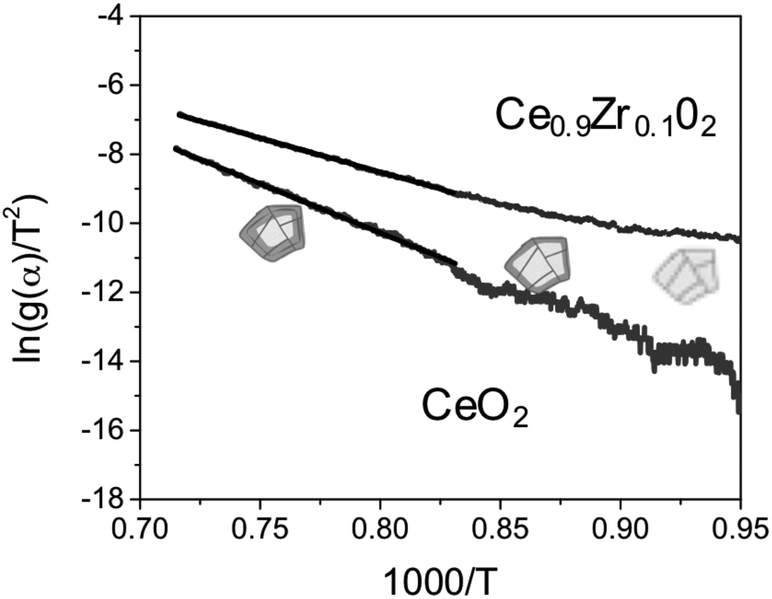 | ||
| Fig. 4 Arrhenius plot of the experimental data for ceria and ceria zirconia using the D3 model, and the corresponding linear fit. The cartoons of the crystals show the reacting layer that forms as the temperature increases. | ||
The reduction of the lattice includes: (i) oxygen diffusion through the surface in the form of O2−; (ii) diffusion in grain and across grain boundaries in the form of oxygen ions. We can then consider two different situations: at low temperatures, the concentration of oxygen in the lattice is high, and oxygen diffusion through the grain boundaries is maximized. Consequently, the rate-limiting step is the oxygen generation at the surface. Conversely, at high temperatures we have less oxygen in the lattice and the diffusion of this oxygen becomes the rate-limiting step. Indeed, the D3 model fits well because it assumes that the reaction at the surface is fast. Thus, the reduction rate is controlled by diffusion of the oxygen ions through the boundary layers.39,40
We can calculate the activation energy for both mechanisms. The activation energy at low temperature is approximately half of that calculated at higher temperatures, ∼100 kJ mol−1 for pure ceria. These results agree with those published by Lai et al.12 for the given range of temperatures (1000–600 °C). Thus, we focus also on the activation energy for the high-temperature step. The pure ceria sample has a higher Ea value (235 kJ mol−1) than Ce0.9Zr0.1O2 (162 kJ mol−1). This tells us that the reduction is faster in the doped ceria. Lower activation energy of Ce0.9Zr0.1O2 is in line with its higher capacity for CO production.
To further check those two mechanisms, we ran another experiment where the metal oxide was reduced isothermally at different temperatures. Fig. 5 shows the temperature profile and the result for Ce0.9Zr0.1O2. Here the samples are heated up to a given temperature and left for one hour. Thus, we can analyse how fast the oxygen is released at the desired temperature. After that, the sample is cooled down to 1000 °C and oxidized with CO2.
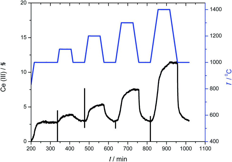 | ||
| Fig. 5 CO/CO2 redox cycling at increasing reduction temperatures, from 1000 to 1400 °C, while the oxidation temperature is kept at 1000 °C, for the sample Ce0.9Zr0.1O2. The blue line gives the temperature program, while the black line shows the Ce(III) concentration profile. | ||
These results were fitted using eqn (4) for all 17 kinetic models. Analysing these fits for Ce0.9Zr0.1O2, we found that at low temperature (1000 °C) the experimental results fit the area-contracting model (R3),33–38,41 reflecting the sintering of the crystals and reduction of the reactive surface area. The XRD and N2 adsorption isotherms (see ESI†) of the samples after the redox cycles indicate that the crystal size is very large (Ce0.9Zr0.1O2 655 nm and CeO2 581 nm). This means that the surface to volume ratio of the crystal is low and consequently the process at low temperatures (surface reduction) reach low values of conversion. However, above 1200 °C, the results fit to 3D diffusion models (D3). This is also in agreement with the non-isothermal results. The pure ceria sample was inactive below 1200 °C. At high temperatures the results fit to D3 models.
From these experiments, we conclude that both Ce0.9Zr0.1O2 and pure ceria are reduced following two mechanisms: below 1100 °C, only the surface is reduced, while at higher temperature the rate-limiting step is the diffusion of oxygen anions through the lattice to the surface.
Kinetics of ceria and doped ceria oxidation
Using the same set of experiments, we now studied the oxidation kinetics (i.e., the reduction of CO2) for the doped ceria. Here, all the analyses pertain to isothermal conditions. The black curve on the bottom graph of Fig. 2 gives information on the effect of the temperature in the oxidation of ceria. Similarly the black curve on the bottom of Fig. 5 gives information on the effect of initial Ce(III) concentration (since the ceria material is reduced at different temperatures, producing five initial Ce(III) concentrations).Fitting the oxidation profile of ceria after reduction at 1400 °C to the 17 kinetic schemes included in the ESI,† we saw that the only acceptable scheme was that of a second-order reaction. This fits with the surface reaction (Scheme 1), where two electrons reduce the carbon from C(IV) to C(II).
 | ||
| Scheme 1 Kroger–Vink notation for the reduction of CO2 by ceria. In this notation Ce′Ce is a small polaron (free electron) and V˙O is an oxygen vacancy.12 | ||
This can be considered as second-order kinetics with respect to the Ce(III) concentration, since we used an excess of CO2. The reaction profile does not change above 700 °C (see Fig. 6). At such high temperatures the reaction rate constant, which shows Arrhenius behavior, is less influenced by the temperature. Mass transport limitations were excluded since experiments performed for pure ceria and doped ceria compounds (Fig. 6 and 8) were run in identical conditions having very similar particle size. Any mass-transport or heat-transport limitation would result in identical profiles. The fact that the profiles differ confirms that there is no mass/heat transfer limitation under these conditions.
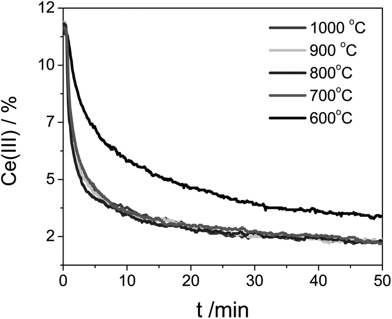 | ||
| Fig. 6 Ce(III) concentration during the Ce0.9Zr0.1O2 oxidation at five different temperatures. The sample was previously reduced at 1400 °C. | ||
The second-order kinetics with respect to Ce(III) means that the reaction is highly sensitive to the Ce(III) concentration. We therefore ran additional experiments using different initial Ce(III) concentrations. Fig. 5 shows the temperature profile (blue stepped graph, top) as well as the degree of reduction (black curve, bottom). After every treatment in inert conditions the sample was cooled down to 1000 °C and oxidized using CO2. We then analysed oxidation step at 1000 °C. Fig. 7 shows how the relative Ce(III) concentration decreases vs. time for different initial concentrations. We see a strong influence of the initial concentration in the kinetics. The more Ce(III) is present at beginning of the oxidation, the higher the reaction rate. These curves also correspond to second-order kinetics, with an oxidation rate constant of 0.043 min−1 [Ce(III)]−1.
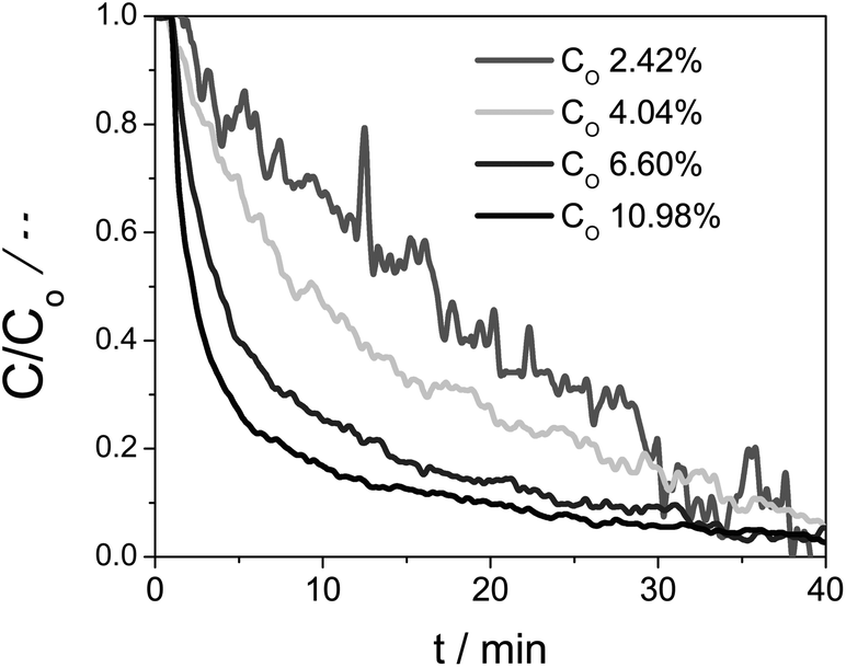 | ||
| Fig. 7 The concentration change of Ce(III) with time starting from four Ce0.9Zr0.1O2 samples with different initial Ce(III) concentrations. Oxidation reactions done at 1000 °C. | ||
Thus, our kinetics analysis of the Ce0.9Zr0.1O2 oxidation suggests that CO2 first approaches the highly reactive reduced Ce0.9Zr0.1O2 surface, and then reacts in a two-electron process, oxidizing two Ce(III) ions to Ce(IV). The oxygen anion easily diffuses into the lattice, “cleaning up” the surface that can then react again with another CO2 molecule.
We then ran the same analysis using the pure ceria sample. Again, we found second-order kinetics. Furthermore, the oxidation rate was constant when we change the temperature range (cf. the curves in Fig. 6 and 8). This indicates that the apparent activation energy is even lower than that of Zr-doped ceria.
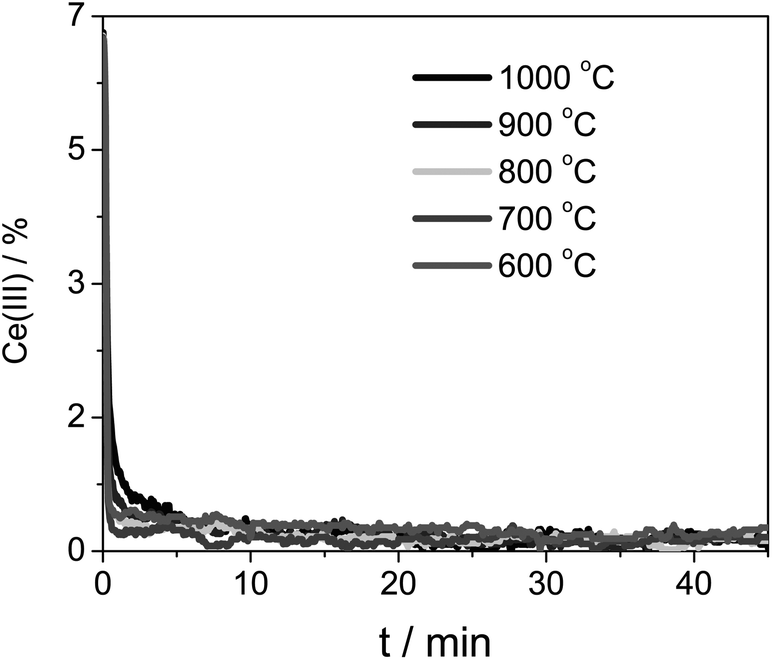 | ||
| Fig. 8 Ce(III) concentration during the CeO2 oxidation at five different temperatures. The sample was first reduced at 1400 °C. | ||
Note that in the case of pure ceria the oxidation was faster, despite its lower initial concentration of Ce(III).42 We kept the same scale for Fig. 6 and 8 for ease of comparison. This may seem counter-intuitive, but bear in mind that though Ce0.9Zr0.1O2 has higher reduction capacity as a whole, the reaction takes place at the surface, which is diluted with a minimum of 10% with Zr (the real value will be even higher because of Zr segregation to the surface, as shown by Bueno and co-workers43–47).
To validate this, we ran another experiment with Ce0.7Zr0.3O2 (see Fig. 9). We see that the reduction capacity strongly increases with the doping, but the regeneration is very slow. In fact, when the temperature of oxidation decreases below 900 °C, the sample does not fully oxidise within 1 h. This experiment shows that doping should be used cautiously to avoid adverse effects.
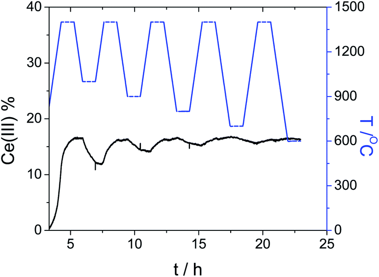 | ||
| Fig. 9 CO/CO2 redox cycling at decreasing oxidation temperatures, from 1000 °C down to 600 °C. The temperature during the reduction steps was kept at 1400 °C. The blue curve shows the temperature program, while the black line shows the Ce(III) concentration for the sample Ce0.7Zr0.3O2. | ||
Finally, analysing the pure ceria sample for initial concentration effects gave similar results to those of Ce0.9Zr0.1O2. The reaction rate was strongly dependent on the initial Ce(III) concentration, and followed second-order kinetics. The rate constant was an order of magnitude higher 0.45 min−1 [Ce(III)]−1 than that found for Ce0.9Zr0.1O2, affirming that the Ce(III) concentration at the surface is higher for pure ceria.
These results show that by choosing the right amount of dopant, one can balance the reduction and oxidation rate, thus maximizing the performance of the rotatory reactor. For example, samples with high dopant loadings are difficult to oxidize, due to their slow kinetics. Conversely, samples with low loading (10% wt) perform better.
Conclusion
Our studies show that the oxidation of Ce(III) follows second-order kinetics, where two electrons are recombined for every CO2 molecule. This process depends on the Ce(III) concentration at the surface. In principle, doping ceria with zirconia is beneficial. The activation energy of reduction is significantly lower for the doped samples than for the pure ceria sample. But the Ce(III) oxidation rate of the doped sample is slower than that of pure ceria, because there are fewer Ce(III) ions available at the doped oxide's surface. The dopant acts as a diluent at the surface of the sample decreasing therefore the concentration of Ce(III) at the surface. Thus, doping has both advantages and limitations, and should be applied carefully if one wants to maximise the efficiency of thermocatalytic cycles for practical energy conversion purposes.Nomenclature
| Symbol | Units | |
|---|---|---|
| Temperature | T | K |
| Conversion | α | — |
| Heating rate | β | K min−1 |
| Activation energy | Ea | J mol−1 |
| Gas constant | R | J mol−1 K−1 |
| Pre-exponential factor | A | Units are different for every kinetic model |
| Reaction rate | k | Units depend on kinetic model |
| Mean experimental temperature | Texp | K |
Acknowledgements
We thank the Dutch National Research School Combination Catalysis (NRSC-C) for funding and Prof. A. Steinfeld (ETH Zurich) for discussions.Notes and references
- V. R. Calderone, N. R. Shiju, D. Curulla-Ferré and G. Rothenberg, Green Chem., 2011, 13, 1950–1959 RSC.
- A. Le Gal, S. Abanades and G. Flamant, Energy Fuels, 2011, 25, 4836–4845 CrossRef CAS.
- S. Abanades, A. Legal, A. Cordier, G. Peraudeau, G. Flamant and A. Julbe, J. Mater. Sci., 2010, 45, 4163–4173 CrossRef CAS.
- J. R. Scheffe and A. Steinfeld, Energy Fuels, 2012, 26, 1928–1936 CrossRef CAS.
- V. R. Calderone, N. R. Shiju, D. Curulla-Ferré, S. Chambrey, A. Khodakov, A. Rose, J. Thiessen, A. Jess and G. Rothenberg, Angew. Chem., Int. Ed., 2013, 52, 4397–4401 CrossRef CAS PubMed.
- P. G. Loutzenhiser, F. Barthel, A. Stamatiou and A. Steinfeld, AIChE J., 2011, 57, 2529–2534 CrossRef CAS PubMed.
- Q.-L. Meng, C.-i. Lee, S. Shigeta, H. Kaneko and Y. Tamaura, J. Solid State Chem., 2012, 194, 343–351 CrossRef CAS PubMed.
- P. Charvin, S. Abanades, E. Beche, F. Lemont and G. Flamant, Solid State Ionics, 2009, 180, 1003–1010 CrossRef CAS PubMed.
- A. Goncalves, J. Silvestre-Albero, E. V. Ramos-Fernandez, J. C. Serrano-Ruiz, J. J. M. Orfao, A. Sepulveda-Escribano and M. F. R. Pereira, Appl. Catal., B, 2012, 113, 308–317 CrossRef PubMed.
- E. V. Ramos-Fernandez, J. C. Serrano-Ruiz, J. Silvestre-Albero, A. Sepulveda-Escribano and F. Rodriguez-Reinoso, J. Mater. Sci., 2008, 43, 1525–1531 CrossRef CAS.
- J. C. Serrano-Ruiz, E. V. Ramos-Fernandez, J. Silvestre-Albero, A. Sepulveda-Escribano and F. Rodriguez-Reinoso, Mater. Res. Bull., 2008, 43, 1850–1857 CrossRef CAS PubMed.
- W. C. Chueh and S. M. Haile, Philos. Trans. R. Soc., A, 2010, 368, 3269–3294 CrossRef CAS PubMed.
- C. Sun, H. Li and L. Chen, Energy Environ. Sci., 2012, 5, 8475–8505 CAS.
- P. Furler, J. Scheffe, M. Gorbar, L. Moes, U. Vogt and A. Steinfeld, Energy Fuels, 2012, 26, 7051–7059 CAS.
- P. Furler, J. R. Scheffe and A. Steinfeld, Energy Environ. Sci., 2012, 5, 6098–6103 CAS.
- J. H. Blank, J. Beckers, P. F. Collignon and G. Rothenberg, ChemPhysChem, 2007, 8, 2490–2497 CrossRef CAS PubMed.
- J. Beckers and G. Rothenberg, Green Chem., 2010, 12, 939–948 RSC.
- J. Beckers and G. Rothenberg, Dalton Trans., 2009, 5673–5682 RSC.
- J. Beckers and G. Rothenberg, Dalton Trans., 2008, 6573–6578 RSC.
- A. Khawam and D. R. Flanagan, Thermochim. Acta, 2005, 436, 101–112 CrossRef CAS PubMed.
- A. Khawam and D. R. Flanagan, J. Phys. Chem. B, 2005, 109, 10073–10080 CrossRef CAS PubMed.
- A. Khawam and D. R. Flanagan, Thermochim. Acta, 2005, 429, 93–102 CrossRef CAS PubMed.
- A. Khawam and D. R. Flanagan, J. Phys. Chem. B, 2006, 110, 17315–17328 CrossRef CAS PubMed.
- A. Khawam and D. R. Flanagan, J. Pharm. Sci., 2006, 95, 472–498 CrossRef CAS PubMed.
- J. Beckers, F. Clerc, J. H. Blank and G. Rothenberg, Adv. Synth. Catal., 2008, 350, 2237–2249 CrossRef CAS PubMed.
- D. Curulla-Ferré, H. Bru, M. Schmücker and M. Roeb, Am. J. Anal. Chem., 2013, 4, 37–45 CrossRef.
- E. C. C. Souza, W. C. Chueh, W. Jung, E. N. S. Muccillo and S. M. Haile, J. Electrochem. Soc., 2012, 159, K127–K135 CrossRef CAS PubMed.
- S. Abanades and A. Le Gal, Fuel, 2012, 102, 180–186 CrossRef CAS PubMed.
- W. C. Chueh, C. Falter, M. Abbott, D. Scipio, P. Furler, S. M. Haile and A. Steinfeld, Science, 2010, 330, 1797–1801 CrossRef CAS PubMed.
- J. Lapp, J. H. Davidson and W. Lipnski, J. Sol. Energy Eng., 2013, 135, 031004 CrossRef.
- D. J. Keene, J. H. Davidson and W. Lipinski, J. Heat Transfer, 2013, 135, 052701 CrossRef.
- S. Gomez-Quero, C. Hernandez-Mejia, R. Hendrikx and G. Rothenberg, Dalton Trans., 2012, 41, 12289–12295 RSC.
- J. Malek, N. Koga, L. A. Perez-Maqueda and J. M. Criado, J. Therm. Anal. Calorim., 2013, 113, 1437–1446 CrossRef CAS PubMed.
- N. Koga, J. M. Criado and H. Tanaka, Thermochim. Acta, 1999, 341, 387–394 CrossRef.
- N. Koga, J. M. Criado and H. Tanaka, J. Therm. Anal., 1997, 49, 1467–1475 CrossRef CAS.
- N. Koga and J. M. Criado, J. Am. Ceram. Soc., 1998, 81, 2901–2909 CrossRef CAS.
- F. J. Gotor, J. M. Criado, J. Malek and N. Koga, J. Phys. Chem. A, 2000, 104, 10777–10782 CrossRef CAS.
- J. M. Criado, L. A. Perez-Maqueda, F. J. Gotor, J. Malek and N. Koga, J. Therm. Anal. Calorim., 2003, 72, 901–906 CrossRef CAS.
- V. Esposito, D. Ni, Z. M. He, W. Zhang, A. S. Prasad, J. A. Glasscock, C. Chatzichristodoulou, S. Ramousse and A. Kaiser, Acta Mater., 2013, 61, 6290–6300 CrossRef CAS PubMed.
- J. Lapp, J. H. Davidson and W. Lipinski, Energy, 2012, 37, 591–600 CrossRef CAS PubMed.
- N. Koga and J. M. Criado, Int. J. Chem. Kinet., 1998, 30, 737–744 CrossRef CAS.
- W. C. Chueh, A. H. McDaniel, M. E. Grass, Y. Hao, N. Jabeen, Z. Liu, S. M. Haile, K. F. McCarty, H. Bluhm and F. El Gabaly, Chem. Mater., 2012, 24, 1876–1882 CrossRef CAS.
- I. Atribak, B. Azambre, A. Bueno-Lopez and A. Garcia-Garcia, Top. Catal., 2009, 52, 2092–2096 CrossRef CAS.
- I. Atribak, B. Azambre, A. B. Lopez and A. Garcia-Garcia, Appl. Catal., B, 2009, 92, 126–137 CrossRef CAS PubMed.
- I. Atribak, A. Bueno-Lopez and A. Garcia-Garcia, Top. Catal., 2009, 52, 2088–2091 CrossRef CAS.
- I. Atribak, A. Bueno-Lopez and A. Garcia-Garcia, Combust. Flame, 2010, 157, 2086–2094 CrossRef CAS PubMed.
- I. Atribak, N. Guillen-Hurtado, A. Bueno-Lopez and A. Garcia-Garcia, Appl. Surf. Sci., 2010, 256, 7706–7712 CrossRef CAS PubMed.
Footnote |
| † Electronic supplementary information (ESI) available: Description of the different kinetics models used, as well as the N2 adsorption isotherms and XRD pattern of the fresh and used sample. See DOI: 10.1039/c4ra01242a |
| This journal is © The Royal Society of Chemistry 2014 |