 Open Access Article
Creative Commons Attribution 3.0 Unported Licence
Novel approach to the processing of meso-macroporous thin films of graphite and in situ graphite–noble metal nanocomposites†
Mohammed
Es-Souni
*,
Dimitri
Schopf
,
Claus-Henning
Solterbeck
and
Matthias
Dietze
Institute for Materials & Surface Technology, University of Applied Sciences, Kiel, Germany. E-mail: mohammed.es-souni@fh-kiel.de
First published on 31st March 2014
Abstract
We report a versatile and novel approach to the processing of supported macro-mesoporous nanographite and in situ nanographite–noble metal nanocomposite films. The precursor is a porous PVDF film that is processed template-free from solution. Among the potential applications of our films we show their suitability for high-performance supercapacitors.
Carbon based materials are of paramount importance in various applications, including fuel cells,1,2 gas sensing,3 hard coatings4 and energy storage.1,5–8 Among the flurry of structures and morphologies of these materials graphite in its various forms is probably most familiar and finds widespread applications (see references above and references therein). Additional functionalities may be generated by designing graphite–metal nanocomposites. For instance carbon and diamond-like-carbon (DLC)-Ag-nanoparticles (Ag-NPs) were applied as bactericidal coatings;9 Ag-NPs incorporated into DLC were also shown to improve life time in aerospace applications involving oxygen ion bombardment.4 Ag–Sn–graphite nanocomposites are suitable as electrodes for fuel cells,10 and carbon–Pt–nanocomposites are well known as electrocatalyst.1,2 Carbon nanomaterials are also particularly suitable for high-performance supercapacitors1,6–8,11 because they can exhibit high surface area, adequate mesoporosity and high chemical stability. For instance carbon nanotubes (CNT) were reported with specific capacitances in the range from 100 to 180 F g−1, depending on electrode morphology and on whether the CNT are multi or single walled.11
Today state of the art double layer capacitors rely, however, on activated porous graphite that is unsurpassed both from the point of view of material and production cost. These advantages are however mitigated by the relatively low specific capacitance that can be achieved with this material.6,11 The main limiting factor has been identified in the inadequate pore structure that rather consists of more micropores (pore diameter <2 nm) and less mesopores, thus limiting electrolyte penetration.12 Designing graphite electrodes with high mesoporosity can therefore boost the performance of these materials while maintaining their cost-effectiveness.
In the present communication we describe a versatile method for preparing supported porous monolithic and in situ metal–graphite nanocomposites, starting from porous polyvinylidene fluoride (PVDF). We demonstrate that these films are promising candidates for supercapacitor applications, but other applications, as outlined above, may readily be explored.
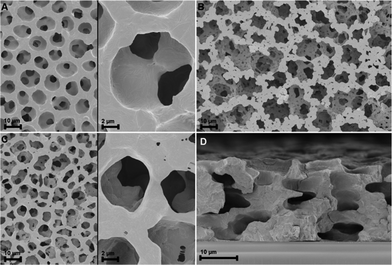
For the preparation of porous PVDF films we refer to our previous publication.12 Briefly, the PVDF powder is dissolved in N,N-dimethylfromamide (C3H7NO, DMF). To this solution we add ammonium nitrate (NH4NO3 which is also well soluble in DMF). The final solution obtained is clear and has a honey-like viscosity of approximately 280 mPa s. The solution can be applied to a substrate, in our case a stainless steel sheet or oxidized silicon, using solution deposition methods, and may also be screen printed. It is during deposition that the system self-organizes so that specific exothermic reactions occur,12 giving rise to hierarchical open porosity, as illustrated in Fig. 1. For the in situ nanocomposites, either AgNO3 or chloroplatinic acid (H2PtCl6) is added to the polymeric solution. The films are subsequently pyrolysed in a tube furnace at 550 °C for 30 to 60 minutes under flowing nitrogen.
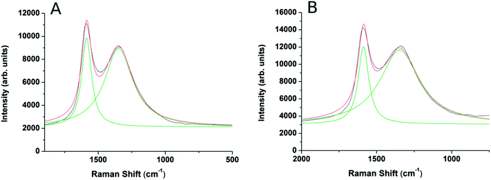
Careful XRD experiments using grazing incidence and long acquisition time (Fig. 1S, ESI†) did not reveal any lines characteristic of graphite or graphite oxides13 thus implying that the graphite phase is amorphous. The Raman scattering spectra confirm the findings of XRD, and show the G and D peaks characteristic of amorphous nanographite,3Fig. 2. The intensity ratio ID/IG may help estimating the domain size using the empirical formula devised by:3,14
 | (1) |
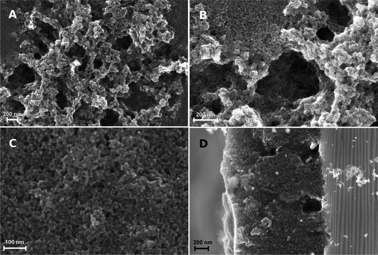
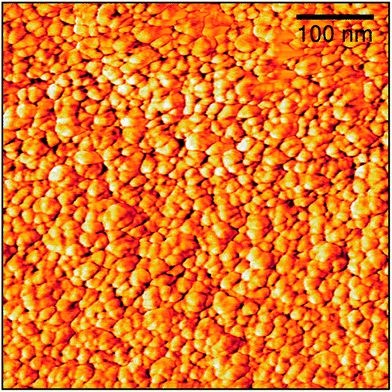
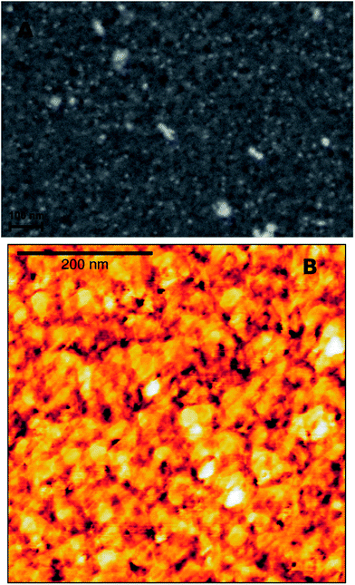
The topography of the graphite layer largely replicates that of the porous PVDF film, but there are areas where only mesoporosity can be seen. This might be amenable to partial melting of the PVDF film and collapse of the pores during pyrolysis. Cracks are not present despite the high thermal expansion mismatch between the stainless steel substrate and the graphite film. Fig. 3 shows the topography of the graphite film with its macro-mesoporous structure with a pore size range from approximately 10 to 250 nm. The cross-section of Fig. 3d shows that the film is approximately 1 μm thick with an overall uniform appearance, and a porosity network throughout the film thickness. The grain morphology and the apparent grain size are better revealed by the AFM micrographs shown in Fig. 4. The films consist of stacks of nano-platelets having an almost uniform size distribution with of 20 to 40 nm, rather consistent with the Raman scattering data. Micrographs of the in situ nanocomposite of graphite and silver are shown in Fig. 5. The Ag-NPs are scattered throughout the graphite film surface with a broad size range from 20 to 80 nm, but isolated particles with larger size were also observed. It is interesting to note that the Ag-NPs are present not only on the surface but also over the full film thickness. These films are particularly suitable for applications involving abrasion but necessitating a continuous supply of, e.g. Ag-ions, for bactericidal coatings.
The graphite–Pt nanocomposites are characterized by much smaller Pt-NPs as illustrated in Fig. 6 (see also Fig. 1S and 2S, ESI† for XRD and EDS analysis, respectively). Although the SEM micrograph shows large isolated clusters, the overall size determined from the AFM phase image, Fig. 6b, ranges from 10 to 18 nm, in agreement with the size obtained from the XRD 111-Pt peak using the Scherrer formula. Also in this case, the Pt-NPs are present both on the surface and in the regions beneath.
We have chosen to explore the charge storage capacity of the macro-mesoporous graphite films in an aqueous solution of 0.5 M H2SO4. Other applications involving the nanocomposite films will be reported in a later stage. The cyclic voltammograms of the films that have the microstructure shown in Fig. 3 are displayed in Fig. 7. The CV curves are fairly similar to those known for carbon materials, and the specific capacitances of 180 ± 40 F g−1 obtained lie in the range of those known for porous activated carbon and other carbon nanomaterial electrodes. In comparison to the plain film (see Fig. 3S, on-line ESI†) the specific capacitance increases by approximately three-fold which underscores the role played by the porosity for this specific application. It should, however, be pointed out that our nanographite films did not undergo any activation treatment. Further, because the charge collector (stainless steel) also supports the film during pyrolysis the formation of an oxide scales during this treatment (see Fig. 2S† where the oxide layer is Fe3O4) should lead to a high contact resistance, consequently impacting negatively film performance. We surmise that film performance could be boosted by employing supports with a thin Au-layer and using an activation treatment.
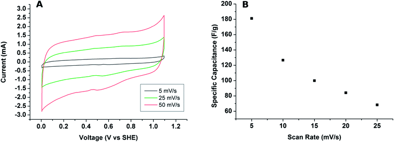 | ||
| Fig. 7 (A) Current vs. voltage (CV) curves of the graphite films in a 0.5 M H2SO4 electrolyte for 3 different voltage scans; (B) plot of the specific capacitance as a function of the scan rate. | ||
Conclusions
In conclusion we have shown a versatile processing route for porous carbon processing on a substrate, starting from a porous PVDF film. Amorphous nanographite platelets are obtained at the fairly low pyrolysis temperature of 550 °C. The graphite films can be deposited on any thermally resistant substrates making a broad range of applications possible. Via the addition of metal salts to the precursor solution we have shown the possibility for in situ graphite–metal nanocomposite processing on graphite–Ag-NPs and graphite–Pt-NPs with rather homogenous distribution of the particles throughout the film thickness. Finally we have shown one potential application of the porous nanographite films for energy storage.Acknowledgements
Financial support of this work is provided by the European Commission, INTERREG IVA, Southern Denmark-Schleswig-K.E.R.N, Project#111-1.2-12.Notes and references
- E. Antolini, Appl. Catal., B, 2009, 88, 1–24 CrossRef CAS PubMed.
- Y. Shao, J. Liu, Y. Wang and Y. Lin, J. Mater. Chem., 2009, 19, 46–59 RSC.
- A. Serra, A. Buccolieri, E. Filippo and D. Manno, Sens. Actuators, B, 2012, 161, 359–365 CrossRef CAS PubMed.
- F. R. Marciano, L. F. Bonetti, R. S. Pessoa, J. S. Marcuzzo, M. Massi, L. V. Santos and V. J. Trava-Airoldi, Diamond Relat. Mater., 2008, 17, 1674–1679 CrossRef CAS PubMed.
- K. Kierzek, E. Frackowiak, G. Lota, G. Gryglewicz and J. Machnikowski, Electrochim. Acta, 2005, 49, 515 CrossRef PubMed.
- L. L. Zhang and X. S. Zhao, Chem. Soc. Rev., 2009, 38, 2520–2531 RSC.
- J. N. Barisci, G. G. Wallace and R. H. Baughman, J. Electroanal. Chem., 2000, 488, 92–98 CrossRef CAS.
- A. Alonso, V. Ruiz, C. Blanco, R. Santamaría, M. Granda, R. Menéndez and S. G. E. de Jager, Carbon, 2006, 44, 441–446 CrossRef CAS PubMed.
- M. L. Morrison, R. A. Buchanan, P. K. Liaw, C. J. Berry, R. L. Brigmon, L. Riester, H. Abernathy, C. Jin and R. J. Narayan, Diamond Relat. Mater., 2006, 15, 138–146 CrossRef CAS PubMed.
- X. Wang, Z. Wen, B. Lin, J. Lin, X. Wu and X. Xu, J. Power Sources, 2008, 184, 508–512 CrossRef CAS PubMed.
- T. Chen and L. Dai, Mater. Today, 2013, 16, 272–280 CrossRef CAS PubMed.
- M. Es-Souni, M. Es-Souni and M. Dietze, RSC Adv., 2011, 1, 579–583 RSC.
- A. B. Bourlinos, D. Gournis, D. Petridis, T. Szabó, A. Szeri and I. Dékány, Langmuir, 2003, 19, 6050 CrossRef CAS.
- D. S. Knight and W. B. White, J. Mater. Res., 1989, 4, 385–393 CrossRef CAS.
Footnote |
| † Electronic supplementary information (ESI) available. See DOI: 10.1039/c4ra00716f |
| This journal is © The Royal Society of Chemistry 2014 |

