Ionic liquid based vibrational energy harvester by periodically squeezing the liquid bridge†
Weijie Konga,
Pengfei Caoa,
Xiaodong Hea,
Long Yua,
Xiangyuan Mab,
Yude Heb,
Liujin Lub,
Xiaoping Zhang*a and
Youquan Deng*b
aSchool of Information Science and Engineering, Lanzhou University, Lanzhou 730000, China. E-mail: zxp@lzu.edu.cn
bCentre for Green Chemistry and Catalysis, Lanzhou Institute of Chemical Physics, CAS, Lanzhou 730000, China. E-mail: ydeng@licp.cas.cn; Fax: +86-931-4968116; Tel: +86-931-4968116
First published on 26th February 2014
Abstract
This paper presents an ionic liquid based vibrational energy harvester by periodically squeezing the liquid bridge, which has excellent characteristics such as the lack of a requirement for an airtight space, stability over a wide operating temperature range (up to 100 °C) and in particular improved output power at high temperatures.
Energy harvesting using ambient vibrations as a potential power source for autonomous sensors and portable applications with low power consumption are gaining much attention.1 Existing methods of mechanical-to-electrical energy conversion include piezoelectric,2 electromagnetic3 and electrostatic techniques.4,5 Each of them has their respective advantages and disadvantages. In the case of the electrostatic approach, it uses a variable capacitor structure to generate electrical power, and the electrostatic devices are easier to integrate in the microsystem, have low cost and possess a simple structure with less circuitry. Most importantly, the electrostatic devices are very suitable for low-frequency (<100 Hz) and low-amplitude vibration sources. However, their output powers are too low to power small electronic devices. Microfluidics6 is a burgeoning multidisciplinary field with interesting engineering, physics, chemistry, nanotechnology and biotechnology applications, with practical applications for the design of systems in which small volumes of fluids (fL to μL) will be handled. Because of their flexibility and small scale, microfluidics-based devices are very suitable for effectively converting the many high-power mechanical energy sources to electricity in a small size which can improve the generated power. In 2011, along with the microfluidics technology and electrostatic methods, a new approach to energy harvesting was proposed.7 The approach runs the electrowetting process in reverse and converts the mechanical energy of liquid (Mercury and Galinstan) motion into electrical energy. When supplied with an external DC bias-voltage source, energy generation is achieved by squeezing the microscopic liquid droplets between vibrating plates, resulting in largely improved power output. Unfortunately, it is not very practical, as it needs an external bias-voltage source and uses toxic mercury. In order to overcome these disadvantages, Moon et al. presented a new method – AC electrical power was generated by mechanically modulating the electrical double layers.8 When the height of the water bridge is mechanically modulated, the electrical double layer capacitors (EDLCs)9,10 formed on the two interfacial areas between bridge and conducting plates are continuously charged and discharged at different phases, which generates electrical power. However, the liquid media in this approach is deionized water which contains trace impurities. Water always evaporates in the air under normal conditions and thus the power output decreases with time accordingly. Furthermore, the water based setup cannot work at relatively high or low temperatures (such as 100 °C or 0 °C). Therefore, development of a liquid medium with low volatility and toxicity, wide liquid temperature range and high power output for a microfluidics-based vibrational energy harvester (VEH) is highly desirable.
Room temperature ionic liquids (RTILs or ILs) have emerged as a novel class of versatile solvent and soft materials due to their negligible vapor pressure, wide liquid temperature range, acceptable electrochemical stability, non-toxicity and environmentally friendliness.11 Besides from these well-known properties, the most important characteristic of ILs is that their properties can be significantly regulated for any particular application by changing their combination of ions. This makes them “designable materials”. These excellent physicochemical properties render them potential candidates for microfluidics-based VEHs.
In this paper, we propose a novel VEH using ILs, which can overcome the problems mentioned above while keeping their high power output. That is, the IL based VEH can work without the need for an airtight space and at high or low temperatures.
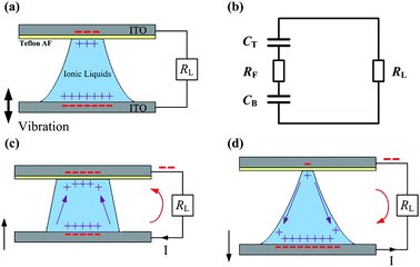
Five imidazolium ILs, [EMIm][N(CN)2], [BMIm][N(CN)2], [EMIm][BF4], [EMIm][SCN] and [BMIm][NO3] were synthesized according to established procedures. The purity of all the ILs was >99%. The viscosity, ionic conductivity, surface tension and density of all the ILs were also measured (Table S1 in the ESI†). Based on the structure of the water-based VEH prototype,8 the IL based VEH prototype was composed of two parallel conducting plates and an IL bridge between them, as shown in Fig. 1(a). The top plate (ITO glass) was covered with a hydrophobic layer (Teflon AF) and the bottom plate was composed of hydrophilic ITO glass. Because the two EDLCs were formed on the contact surfaces between the IL bridge and the conducting plates, the electrical circuit model can be expressed as shown in Fig. 1(b), which includes two EDLCs CT and CB, an electronic resistor RF denoting the IL bridge resistance and a resistive load RL. When the IL bridge between the plates was periodically squeezed by vertically vibrating the bottom plate, the top contact area changed periodically due to the hydrophobicity of the top surface. This resulted in the variation of the top EDLC capacitance, while the bottom contact area did not change due to the small contact angle and pinning effect of the hydrophilic bottom surface and thus the bottom EDLC capacitance did not change appreciably. Fig. 1(c) and (d) show that each periodic change in the top EDLC capacitance resulted in the variation of the total charge stored in the top EDLC and the partial free charge flowed from the bottom EDLC to the top EDLC (when the top EDLC increases) or from the top EDLC to the bottom EDLC (when the top EDLC decreases) in the electrical circuit, which generated AC electrical power. The different wetting properties of the two conducting plates made the top contact area increase in order to improve the output power. A differential equation8 based on the electrical circuit model shown in Fig. 1(b) was used for the calculations (electrical circuit model and numerical calculations are found in the ESI†). The voltage drop across the load resistance was measured and the effective power was calculated from the root-mean-square (RMS) voltage. The generated power was improved by increasing the volume of the IL bridges and the maximum volumes of the IL bridges were determined by the capillary length of the ILs, which is  .8 In this expression, γ, ρ and g correspond to the surface tension, density of the ILs and gravitational acceleration, respectively. By simple geometric calculation, the maximum volume of the IL bridges is the volume of a half sphere with a radius equal to the capillary length. When the volume of the droplet exceeds the maximum volume, the IL droplet degenerates into a pancake shape,12 which will reduce the power generation substantially. For the ILs discussed in this paper, all of their maximum volumes are larger than about 15 μL. Consequently, the volumes of the liquid bridges are set to 15 μL for convenience of comparison and high power output.
Fig. 2 demonstrates the calculated and measured instantaneous output voltage and the corresponding instantaneous power across the load resistor when a 15 μL [EMIm][N(CN)2] bridge is positioned. When the bottom plate is vibrated according to L![[thin space (1/6-em)]](https://www.rsc.org/images/entities/char_2009.gif) sin(2πft), the instantaneous output voltage fluctuates with positive and negative peaks, where L, f and t are the vibrational amplitude, frequency and time, respectively. In terms of the measured data, the maximum negative voltage and positive voltage are about 389 mV and 182 mV, respectively. Correspondingly, the maximum instantaneous power and effective power are about 5.0 nW and 1.2 nW, respectively. The contact areas between the liquid bridge and conducting plates were measured for numerical calculation. The maximum and minimum top contact areas at a vibrational amplitude of 0.35 mm and frequency of 10 Hz were about 14.8 mm2 and 4.8 mm2, respectively, and the top contact area variation in calculation was approximated by the sine function of 9.8 + 5.0
sin(2πft), the instantaneous output voltage fluctuates with positive and negative peaks, where L, f and t are the vibrational amplitude, frequency and time, respectively. In terms of the measured data, the maximum negative voltage and positive voltage are about 389 mV and 182 mV, respectively. Correspondingly, the maximum instantaneous power and effective power are about 5.0 nW and 1.2 nW, respectively. The contact areas between the liquid bridge and conducting plates were measured for numerical calculation. The maximum and minimum top contact areas at a vibrational amplitude of 0.35 mm and frequency of 10 Hz were about 14.8 mm2 and 4.8 mm2, respectively, and the top contact area variation in calculation was approximated by the sine function of 9.8 + 5.0![[thin space (1/6-em)]](https://www.rsc.org/images/entities/char_2009.gif) sin(20πt) mm2. When decreasing the amplitude, the top contact area variation decreased. The bottom contact area was about 17.2 mm2 and was nearly constant in the experiments due to the small contact angle and pinning effects. It is obvious that the calculated results, based on electrical circuit model, closely match the measured results, but the detailed waveform deviates near the positive voltage peak. It may be speculated that the variation in the experimental contact area between the IL bridge and top plate is not exactly sinusoidal, because of the hydrodynamic flow in the IL bridges and the imperfections in the surface of the Teflon-coated top plate, while the contact area in the calculations is sinusoidal.
sin(20πt) mm2. When decreasing the amplitude, the top contact area variation decreased. The bottom contact area was about 17.2 mm2 and was nearly constant in the experiments due to the small contact angle and pinning effects. It is obvious that the calculated results, based on electrical circuit model, closely match the measured results, but the detailed waveform deviates near the positive voltage peak. It may be speculated that the variation in the experimental contact area between the IL bridge and top plate is not exactly sinusoidal, because of the hydrodynamic flow in the IL bridges and the imperfections in the surface of the Teflon-coated top plate, while the contact area in the calculations is sinusoidal.
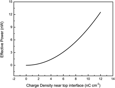
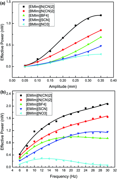
The dependence of the power generation on the vibrational amplitude and frequency with different ILs was investigated for a sinusoidal vibration as shown in Fig. 3. We can see that the effective power increases with the vibrational amplitude for all five ILs in a limited range. The variation in the contact area between the IL bridge and the top plate increases with the vibrational amplitude. A large variation in the contact area leads to an increase in the top EDLC capacitance variation and thus the free charge flowing across the load increases, which results in an increase in power generation. Meanwhile, for the same vibrational amplitude of 0.35 mm and frequency of 10 Hz, the output power follows the order P[EMIm][N(CN)2] > P[BMIm][N(CN)2] > P[EMIm][BF4] > P[EMIm][SCN] > P[BMIm][NO3]. Two of the most important reasons relate to the differences in the charge densities near the interface between the top conducting plates and the IL bridge, and the differences in the IL viscosities. A high charge density near the top interface leads to an increase in the charge stored in the top EDLC, and therefore the free charge flowing through the electrical circuit when the variation of the top EDLC capacitance remains constant (i.e. the variation in the top contact area is nearly constant). Thus the output power increases sharply with charge density near the top interface. This conclusion is consistent with the prediction obtained from the electrical circuit model, as shown in Fig. 4. Moreover, the viscosity can also influence the output power. A low viscosity guarantees a large variation in the contact area between the IL bridge and the top plate during the vibration cycle and therefore the output power increases. These two main factors jointly determine the generated power. Particularly, the structures of the ILs primarily influence the charge density near the top interface and the viscosity, and thus the output power substantially depends on this factor. For [N(CN)2]−-based ILs with different cations ([EMIm][N(CN)2] and [BMIm][N(CN)2]), absorption of the cation onto the top plate becomes stronger as the length of the alkyl chain decreases,13 which results in an increase in the charge density near the top interface. Furthermore, the viscosities of ILs with longer alkyl chains are larger, and as a consequence, P[EMIm][N(CN)2] > P[BMIm][N(CN)2]. For [EMIm]+-based ILs with different anions and similar viscosities ([EMIm][N(CN)2] and [EMIm][SCN]), P[EMIm][N(CN)2] > P[EMIm][SCN], it may be that the differences in the anion size, cation–anion interaction and the top surface–anion interaction cause more cations and fewer anions to be present in the vicinity of the top interface for the [EMIm][N(CN)2] IL. As a result, a larger charge density of [EMIm][N(CN)2] near the top interface generates more power. In this work, the vibrational frequency was not more than 30 Hz because the complex hydrodynamic effects encountered at high frequencies would deform the IL bridge.14,15 From the results shown in Fig. 3(b), for ILs with relatively large viscosities ([BMIm][NO3], [EMIm][BF4] and [BMIm][N(CN)2]), the effective power increases at first, reaches a maximum and then decreases with the vibrational frequency. This trend arises from the negative impact of viscosity-induced damping on the change in the top contact area which outpaces the positive impact of frequency increase when the vibration frequency is relatively high. Moreover, the optimal frequencies generating maximum power for the three ILs are different. Considering viscosity η[BMIm][N(CN)2] (27 cP) < η[EMIm][BF4] (45 cP) < η[BMIm][NO3] (168 cP), the optimal frequencies are fopt[BMIm][N(CN)2] (28 Hz) > fopt[EMIm][BF4] (22 Hz) > fopt[BMIm][NO3] (12 Hz). For ILs with relatively small viscosities ([EMIm][N(CN)2] and [EMIm][SCN]), the effective power always increases with frequency in the range 6–30 Hz. This means that the optimal frequencies of the two ILs are 30 Hz. It is interesting to note that the effective power P[EMIm][BF4] > P[EMIm][SCN] is true for frequencies smaller than 20 Hz, while that of [EMIm][BF4] starts to decrease in the high frequency range. For the 15 μL IL bridges, the generated maximum effective powers are about 2.1 nW for [EMIm][N(CN)2], 1.7 nW for [BMIm][N(CN)2], 1.2 nW for [EMIm][SCN], 1.0 nW for [EMIm][BF4] and 0.3 nW for [BMIm][NO3] at their optimal vibrational frequencies. To sum up, imidazolium ILs with short alkyl chains and low viscosities can output more power in energy harvesting. The output powers are of the same order of magnitude for several nanowatts with recent droplet based mechanical energy harvesters.16,17
 | ||
| Fig. 4 The effective power versus charge density near the top interface of the VEH according to the electrical circuit model. | ||
The water based VEH was only able to operate within a narrow temperature range (0 to 60 °C) because of the properties of water. However, IL based VEHs will probably work well even at 100 °C because of the wide liquid temperature range and good thermal stability of the ILs. So the performance of the IL based VEH at high temperature was further investigated. Because of the better thermostability of [EMIm][BF4], we chose the [EMIm][BF4] based VEH as an example. Fig. 5 shows that the effective power increases with increasing temperature at the same vibrational amplitude and frequency. This probably results from the decreased ion association in ILs with increasing temperature18,19 and the obvious temperature-induced decrease in viscosity.20,21 An increase in the concentration of simple ions as a consequence of the breakdown of the aggregates results in the adsorption of more cations to the top interface13,22 and then the charge density near the top interface increases, which improves the output power rapidly. A low viscosity guarantees a large variation in the contact area between the IL bridge and the top plate during the vibrational cycle. A large variation in the contact area leads to an increase in power generation. As can be seen from Fig. 5(b), the optimal frequency shifts to the higher frequency region when the temperature increases. Especially at 100 °C, the effective power consistently increases with the vibrational frequency, and the maximum effective power can reach to 12.1 nW. A low viscosity at a high temperature reduces the viscosity-induced damping on the change in the top contact area and the combined effect of a frequency increase is an improvement in the generated power at a vibrational frequency of 6 Hz to 30 Hz. Therefore, increasing the temperature raises the power generation of the IL based VEH.
Following this, we compared the output effective powers of the [EMIm][BF4] bridge and water bridge. The results are shown in Fig. 6. As one can see, the water based VEH can generate more power than the [EMIm][BF4] based VEH at 25 °C, especially at high vibrational frequencies. The very small viscosity of water (about 1 cP) is responsible for this large difference. The power ratios of [EMIm][BF4] to water are 0.70, 0.18 and 0.08 at 6 Hz, 18 Hz and 30 Hz, respectively. Because viscosity plays a more important role in power generation at high frequencies, the difference between the output powers at high frequencies is larger. At an operating temperature of 100 °C, the generated power of the [EMIm][BF4] based VEH improves substantially compared with that at 25 °C, and closely follows the water based VEH at 25 °C. This means that the output powers of IL and water based VEHs8 are comparable.
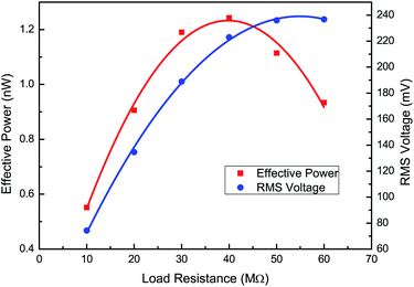
To maximise the power output delivered to the load, the impedances of load and VEH should be matched and minimized. A trend can be seen in Fig. 7. With increasing load resistance, a local effective power maximum can be found at the optimal load resistance that matches the source output impedance, while the RMS voltage increases consistently. The [EMIm][N(CN)2] based VEH can generate a maximum power of 1.24 nW for vibrations at 10 Hz on an optimal load resistance of 40 MΩ. This experimental data is in good agreement with the electrical circuit model prediction of 38 MΩ.
In order to power autonomous sensors, the effective power must be increased. One method is to form numerous small and equally sized IL bridges in parallel between two plates. It is estimated that an IL based VEH with 1 m2 liquid–substrate overlap area (about 58![[thin space (1/6-em)]](https://www.rsc.org/images/entities/char_2009.gif) 000 IL bridges when considering bridge–bridge interspaces) will generate about 0.12 mW effective power at room temperature and about 0.70 mW effective power at 100 °C. Another method is to use electret as a dielectric film on the top plate. Electret is an electrically charged dielectric that can retain charge for years.23 Because electret can lead to an increase in the charge density near the interface between the IL bridge and the top plate, the effective power is expected to increase drastically.
000 IL bridges when considering bridge–bridge interspaces) will generate about 0.12 mW effective power at room temperature and about 0.70 mW effective power at 100 °C. Another method is to use electret as a dielectric film on the top plate. Electret is an electrically charged dielectric that can retain charge for years.23 Because electret can lead to an increase in the charge density near the interface between the IL bridge and the top plate, the effective power is expected to increase drastically.
In conclusion, an IL based VEH made by periodically squeezing a liquid bridge has been proposed and demonstrated. The effects of the physicochemical properties of the ILs and operating temperatures on power generation have been investigated. The results indicate that VEHs prepared using imidazolium ILs with short alkyl chains and low viscosities can generate more power. Moreover, the output power of IL based VEHs improves with increasing operating temperatures and the output power at 100 °C reaches about 22 times that at 15 °C for [EMIm][BF4]. Compared with water based VEHs, the IL based VEHs need not be sealed in airtight containers and can operate over a wide temperature range. Besides, the generated power of IL based VEHs affected by the physicochemical properties of ILs can be further improved through rational design and synthesis of ILs. At room temperature, the maximum power density can reach to about 0.12 mW m−2 while it is 0.70 mW m−2 at 100 °C. We believe that this new energy harvester can be applied as a power source for self-sustainable wireless sensor networks and portable electronics with low power consumption in the near future.
Acknowledgements
This work was supported by the National Natural Science Foundation of China (no. 21373247 and no. 61205204), and the “Spring Sunshine” Plan (no. Z2011029).Notes and references
- S. Roundy, E. S. Leland, J. Baker, E. Carleton, E. Reilly, E. Lai, B. Otis, J. M. Rabaey, P. K. Wright and V. Sundararajan, IEEE Pervasive Computing, 2005, vol. 4, pp. 28–36 Search PubMed.
- I. C. Lien and Y. C. Shu, Smart Mater. Struct., 2012, 21, 082001 CrossRef.
- S. P. Beeby, R. N. Torah, M. J. Tudor, P. Glynne-Jones, T. O'Donnell, C. R. Saha and S. Roy, J. Micromech. Microeng., 2007, 17, 1257–1265 CrossRef.
- Y. Naruse, N. Matsubara, K. Mabuchi, M. Izumi and S. Suzuki, J. Micromech. Microeng., 2009, 19, 094002 CrossRef.
- D. Hoffmann, B. Folkmer and Y. Manoli, J. Micromech. Microeng., 2009, 19, 094001 CrossRef.
- G. M. Whitesides, Nature, 2006, 442, 368–373 CrossRef CAS PubMed.
- T. Krupenkin and J. A. Taylor, Nat. Commun., 2011, 2, 448 CrossRef PubMed.
- J. K. Moon, J. Jeong, D. Lee and H. K. Pak, Nat. Commun., 2013, 4, 1487 CrossRef PubMed.
- P. Sharma and T. S. Bhatti, Energy Convers. Manage., 2010, 51, 2901–2912 CrossRef CAS PubMed.
- A. Lewandowski and M. Galinski, J. Phys. Chem. Solids, 2004, 65, 281–286 CrossRef CAS PubMed.
- M. Armand, F. Endres, D. R. MacFarlane, H. Ohno and B. Scrosati, Nat. Mater., 2009, 8, 621–629 CrossRef CAS PubMed.
- P. G. Degennes, Rev. Mod. Phys., 1985, 57, 827–863 CrossRef CAS.
- V. Lockett, R. Sedev, J. Ralston, M. Horne and T. Rodopoulos, J. Phys. Chem. C, 2008, 112, 7486–7495 CAS.
- X. Zhang, R. S. Padgett and O. A. Basaran, J. Fluid Mech., 1996, 329, 207–245 CrossRef CAS.
- D. J. Mollot, J. Tsamopoulos, T. Y. Chen and N. Ashgriz, J. Fluid Mech., 1993, 255, 411–435 CrossRef CAS.
- E. Yildirim and H. Kulah, Microfluid. Nanofluid., 2012, 13, 107–111 CrossRef.
- Z. C. Yang, E. Halvorsen and T. Dong, Appl. Phys. Lett., 2012, 100, 213905 CrossRef PubMed.
- R. Atkin and G. G. Warr, J. Phys. Chem. C, 2007, 111, 5162–5168 CAS.
- M. Mezger, H. Schroder, H. Reichert, S. Schramm, J. S. Okasinski, S. Schoder, V. Honkimaki, M. Deutsch, B. M. Ocko, J. Ralston, M. Rohwerder, M. Stratmann and H. Dosch, Science, 2008, 322, 424–428 CrossRef CAS PubMed.
- J. Jacquemin, P. Husson, A. A. H. Padua and V. Majer, Green Chem., 2006, 8, 172–180 RSC.
- X. D. Hu, S. G. Zhang, C. Qu, Q. H. Zhang, L. J. Lu, X. Y. Ma, X. P. Zhang and Y. Q. Deng, Soft Matter, 2011, 7, 5941–5943 RSC.
- M. Holovko, V. Kapko, D. Henderson and D. Boda, Chem. Phys. Lett., 2001, 341, 363–368 CrossRef CAS.
- S. Boisseau, G. Despesse and A. Sylvestre, Smart Mater. Struct., 2010, 19, 075015 CrossRef.
Footnote |
| † Electronic supplementary information (ESI) available: Details of the structure and characterization of ionic liquids, device fabrication and assembly, electrical circuit model, numerical calculations and other experimental results. See DOI: 10.1039/c4ra00629a |
| This journal is © The Royal Society of Chemistry 2014 |


