 Open Access Article
Creative Commons Attribution 3.0 Unported Licence
1.8 V symmetric supercapacitors developed using nanocrystalline Ru films as electrodes†
Hui Xia*ab,
Bo Liab and
Li Luc
aSchool of Materials Science and Engineering, Nanjing University of Science and Technology, Xiaolingwei 200, Nanjing 210094, China. E-mail: xiahui@njust.edu.cn; Fax: +86 25 84303408; Tel: +86 25 84303408
bHerbert Gleiter Institute of Nanoscience, Nanjing University of Science and Technology, Xiaolingwei 200, Nanjing 210094, China
cDepartment of Mechanical Engineering, National University of Singapore, 9 Engineering Drive 1, 117576, Singapore
First published on 12th February 2014
Abstract
Nanocrystalline Ru film is deposited on Ni foam by a chemical replacement reaction. The deposited Ru film exhibits a mesoporous structure comprising nanocrystallites and nanopores of 2–3 nm in diameter. A 1.8 V symmetric supercapacitor is developed using nanocrystalline Ru films as both negative and positive electrodes.
To meet the increasing needs for sustainable and renewable power sources in the modern electronic industry, many efforts have been devoted to developing flexible, lightweight and environmentally friendly energy storage devices, such as batteries and supercapacitors. Supercapacitors, also called electrochemical capacitors, with higher energy density compared to traditional electrostatic capacitors and higher power density compared to rechargeable batteries, are promising candidates for the next-generation power devices.1 Currently, most commercial supercapacitors are based on two symmetric activated carbon (AC) electrodes separated by a polymeric membrane impregnated with an organic electrolyte.2 The organic electrolytes, usually with high voltage window up to 4 V, have many disadvantages including low ionic conductivity, high cost, tedious purification processes and flammability. On the contrary, aqueous electrolytes have merits in terms of high ionic conductivity, low cost, inflammability, and environmental benignity, which make the supercapacitors using aqueous electrolytes more desirable for practical applications. However, the restriction of aqueous electrolytes is a limited operating voltage of about 1.23 V at which water decomposes. To further improve the energy density of aqueous electrolyte-based supercapacitor, widening the voltage window is the key. One strategy is to select electrode materials that have high overpotentials for hydrogen and/or oxygen evolutions. Another one is to combine different positive and negative electrode materials that have well-separated potential windows to make asymmetric supercapacitors, enabling widening of the cell voltage.
Various types of aqueous electrolyte-based asymmetric supercapacitors, such as AC//MnO2 and AC//Ni(OH)2, have been developed to achieve a cell voltage of 1.4–2.0 V.3–8 AC is usually used as the negative electrode due to its higher overpotential for hydrogen evolution. However, AC is relatively low in mass specific capacitance, so exploring alternative material with higher specific capacitance as negative electrode is critical to further increase the device's energy density. Several studies indicated that metal oxides could also be used as negative electrodes in asymmetric supercapacitors.9–11 Assembling symmetric supercapacitor using the same electrode material for both cathode and anode could simplify the fabrication procedure. However, except for AC, symmetric supercapacitors using metal oxides as electrode materials usually show much lower cell voltages compared to those of asymmetric supercapacitors. Reddy et al. reported a symmetric MnO2//MnO2 supercapacitor with a cell voltage of 0.7 V and Dubal et al. fabricated a symmetric Mn3O4//Mn3O4 supercapacitor with a cell voltage of 1 V.12,13 A symmetric supercapacitor based on two nickel-cobalt oxide electrodes was fabricated by Lu et al., giving a cell voltage of 0.5 V.14 Only recently, Xia et al. developed a high-voltage symmetric RuO2//RuO2 supercapacitor that gives a cell voltage of 1.6 V.15 Although the cost is relatively high, RuO2 has a high capacitance, reversible charge/discharge features, and good electrical conductivity, all of which make it promising for high-performance supercapacitors. Despite RuO2, nanocrystalline Ru could also be a promising electrode material for supercapacitors as Juodkazis et al.16 suggested the theoretical capacitance of Ru is about 3800 F g−1 based on the reversible faradaic process as follows:
| Ru + 3H2O ⇔ Ru(OH)3 + 3H+ + 3e− | (1) |
In this work, nanoporous Ru thin film was deposited on the Ni foam by a chemical replacement reaction. It was found that the Ru film on the Ni foam exhibits high overpotentials for both hydrogen and oxygen evolutions in the neutral electrolyte of 1 M Na2SO4 and large areal capacitance in both negative and positive windows. A 1.8 V symmetric supercapacitor, having promising supercapacitive behavior, was developed using the Ru films as both cathode and anode.
The Ni foam has an open pore structure with an area density of approximately 500 g m−2, and an average pore size of 0.2 to 0.5 mm. Before being used as a substrate, the Ni foam was washed with a solution of 1 wt% HCl for 5 min. After that, it was cleaned with an ultrasonic cleanser in ethanol bath for 10 min. The Ni foam was then dipped into a RuCl3 solution (0.1 M) at room temperature for 10 min for the chemical replacement reaction as follows:17
| 3Ni + 2Ru3+ → 2Ru + 3Ni2+ | (2) |
Finally, the Ru/Ni-foam was washed with distilled water and dried in a vacuum oven at 60 °C for 1 h.
The crystalline structure of the Ru/Ni foam was characterized by X-ray diffraction (XRD, Shimadzu X-ray diffractometer 6000, Cu-Kα radiation) with a scan rate of 2° min−1. The surface morphology of Ru/Ni foam was investigated by field emission scanning electron microscopy (FESEM, Hitachi, S-4300). A small amount of Ru film sample was obtained from the Ru/Ni-foam by ultrasonic vibration for 10 min in ethanol. The collected Ru sample was further investigated by transmission electron microscopy (TEM, JEOL, JEM-2010). The Ru/Ni-foam with a geometric area of about 1 cm2 was used as the electrode for electrochemical characterization. The electrochemical performance of Ru/Ni-foam was investigated by cyclic voltammetry (CV) and galvanostatic charge/discharge using a Solatron 1287 electrochemical interface. The electrochemical performance of individual Ru/Ni foam electrode was tested using a three-electrode cell with a platinum foil counter electrode and an Ag/AgCl (saturated KCl) reference electrode. The symmetric supercapacitor was tested in a two-electrode cell using two Ru/Ni foam electrodes. For both three-electrode and two-electrode cells, 1 M Na2SO4 was used as the electrolyte.
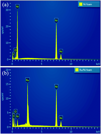
It is difficult to see any difference from the XRD patterns of the Ni foam and the Ru/Ni-foam (Fig. S1, ESI†). For both XRD pattern, three peaks located at 2θ = 44.3, 51.7, and 76.4° can be attributed to the characteristic (111), (200) and (220) crystallographic planes of metallic nickel with a fcc structure (JCPDS card no. 65-0380). It is possible that the diffraction peaks from Ni foam are too strong so that the diffraction peaks from the nanocrystalline Ru film are too weak to be observed. Moreover, some diffraction peaks of metallic Ru with hcp structure (like (101)) could be overlapped with the Ni diffraction peaks. The insets in Fig. S1† show the photo images of the Ni foam and Ru/Ni-foam. After the chemical replacement reaction, the color of the Ni foam changes from sliver to black, indicating successful deposition Ru on Ni foam. The deposition of Ru film on Ni foam was further investigated by energy-dispersive X-ray spectrometry (EDS) analysis. The EDS spectra of the Ni foam before and after Ru deposition are shown in Fig. 1. A strong peak of Ru was clearly detected after the deposition, confirming the successful deposition of Ru on the Ni foam.
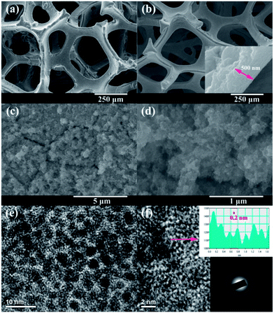
Fig. 2a and b show the low-magnification FESEM images of the Ni foam before and after the chemical replacement reaction. After the chemical replacement reaction, the surface morphology of the Ni foam appears even smoother, indicating the successful deposition of a uniform Ru film. The inset in Fig. 2b shows the cross-section view of the film from a peeling area, where we can estimate the thickness of the film to be about 500 nm. Fig. 2c and d show the FESEM images of the Ni foam after Ru deposition with high magnifications. It can be seen that the film is highly porous, consisting of very fine nanoparticles. The microstructure of the film was further investigated by TEM. As shown in Fig. 2e, the Ru film presents a fine-porous structure with continuous three-dimensional framework porosity (also see Fig. S2, ESI†). The average particle size for the Ru particles is about 2–3 nm and similar size is observed for the pores. At higher magnification, the TEM image (Fig. 2f) reveals the spherical nanoparticles are single crystalline exhibiting lattice fringes characteristic for metallic Ru. The lattice fringes with an interplanar spacing of 0.234 nm correspond to the Ru (100) planes (Fig. S2, ESI†). The electron diffraction pattern of the Ru nanoparticles (inset in Fig. 2f) shows broad rings with the d-spacings, of hcp Ru metal. The broadening of the diffraction rings suggests that the particles are small and/or are of low crystallinity.18
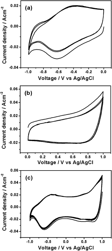
CVs of the Ru thin film electrode in various voltage windows in a three-electrode cell at a scan rate of 50 mV s−1 are shown in Fig. 3. As shown in Fig. 3a and b, the CVs of the Ru thin film electrode exhibit similar rectangular shape in both negative voltage window (−1 to 0 V vs. Ag/AgCl) and positive voltage window (0–1 V vs. Ag/AgCl), indicating ideal capacitive behavior. Due to the loss of Ni during the chemical replacement reaction, it is difficult to calculate the mass specific capacitance of the Ru thin film electrode. The areal specific capacitances of Ru thin film electrode in the negative and positive voltage windows are 0.25 and 0.27 F cm−2, respectively. Fig. 3c shows the CV of the Ru thin film electrode between −1 and 1 V vs. Ag/AgCl at a scan rate of 50 mV s−1. It can be seen that the Ru thin film electrode has good electrochemical stability in a very broad potential window of about 2 V in 1 M Na2SO4 aqueous electrolyte. Based on the operating voltage widow determined by the CV results, a symmetric supercapacitor using two Ru thin film electrodes is expected to have a high working voltage up to 2 V in 1 M Na2SO4. The high working voltage of the Ru//Ru symmetric supercapacitor is due to the broad voltage window of Ru electrode in the neutral aqueous electrolyte. As observed from the CV results, it is clear to see that water starts to decompose on the Ru electrode when the voltage increases to 1 V or decreases to −1 V. The CV results indicate that the Ru/Ni foam has high overpotentials for both hydrogen and oxygen evolution in the neutral aqueous electrolyte. CVs of the bare Ni foam in various voltage windows were measured for comparison purpose (Fig. S3, ESI†). It was found that CVs of the bare Ni foam have currents 10 times smaller than those of the Ru/Ni foam, indicating that the capacitance was mainly contributed by the Ru nanocrystallines.
 | ||
| Fig. 3 CV curves of the Ru/Ni foam electrode in various voltage windows: (a) −1 to 0 V, (b) 0–1 V and (c) −1 to 1 V vs. Ag/AgCl at a scan rate of 50 mV s−1. | ||
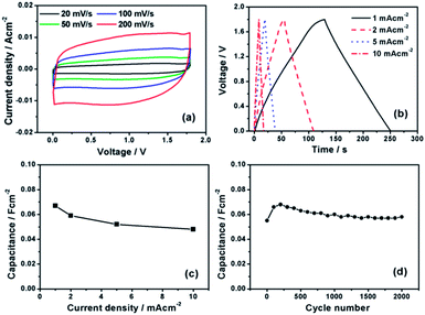
A symmetric Ru//Ru supercapacitor was assembled in the two-electrode Swagelok cell. Fig. 4a shows the CVs of the full cell between 0 and 1.8 V at various scan rates between 20 and 200 mV s−1. However, the operating voltage of the Ru//Ru symmetric supercapacitor cannot be extended to 2 V due to a sudden current leap occurs at voltage beyond 1.8 V, which is probably due to the water decomposition (Fig. S4, ESI†). The CV curves of the full cell exhibit quasi-rectangular shape with a mirror image feature even at a high scan rate of 200 mV s−1, indicating highly reversible charge/discharge responses and good rate capability for the device. The galvanostatic charge/discharge curves of the symmetric supercapacitor at different current densities are shown in Fig. 4b. The linear relationship between the voltage and time indicates a typical capacitor behavior. The specific areal capacitances of the fabricated Ru//Ru symmetric supercapacitor can be calculated based on the charge/discharge curves. As shown in Fig. 4c, the highest areal capacitance of the Ru//Ru symmetric supercapacitor can reach about 67 mF cm−2 at a current density of 1 mA cm−2, which is larger than the values reported for other symmetric supercapacitors, such as MnO2//MnO2 (∼26 mF cm−2) and carbon//carbon (∼31 mF cm−2) supercapacitors,19,20 Even at a high current density of 10 mA cm−2, the Ru//Ru symmetric supercapacitor can still deliver a high areal capacitance of 48 mF cm−2, indicating excellent rate performance. Fig. 4d shows the cycle performance of the Ru//Ru symmetric supercapacitor charged and discharged at a current density of 2 mA cm−2 for 2000 cycles. The initial increase of the capacitance for the first 200 cycles is due to the electrode activation process, which involves the electrolyte penetration into the Ru film, resulting in an increase of the electrode–electrolyte interface. The decrease of the capacitance for the following cycles is probably due to the dissolution and detachment of the active material into the electrolyte during the long time cycling. No capacitance loss was achieved by the device after 2000 cycles, indicating great cycling stability of the Ru//Ru symmetric supercapacitor.
In summary, nanoporous Ru thin film consisting of ultrafine nanoparticles was deposited on the Ni foam by chemical replacement reaction. The Ru thin film electrode exhibited high electrochemical stability in 1 M Na2SO4 aqueous electrolyte and large areal capacitances in both negative and positive voltage windows. A 1.8 V symmetric supercapacitor has been developed by using two Ru thin film electrodes. The Ru//Ru symmetric supercapacitor exhibited large areal capacitance up to 68 mF cm−2 at a current density of 1 mA cm−2 and good rate capability. Moreover, no capacitance loss was achieved for the Ru//Ru symmetric supercapacitor after 2000 charge/discharge cycles, indicating excellent cycle performance. The present results indicate the nanocrystalline metals could be promising electrode materials to develop high voltage symmetric supercapacitors.
This work was supported by National Natural Science Foundation of China (no. 51102134), Natural Science Foundation of Jiangsu Province (no. BK20131349), China Postdoctoral Science Foundation (no. 2013M530258), and Jiangsu Planned Projects for Postdoctoral Research Funds (no. 1202001B).
Notes and references
- J. Jiang, Y. Y. Li, J. P. Liu, X. T. Huang, C. Z. Yuan and X. W. Low, Adv. Mater., 2012, 24, 5166 CrossRef CAS PubMed.
- A. Burke, Electrochim. Acta, 2007, 53, 1083 CrossRef CAS PubMed.
- Q. T. Qu, Y. Shi, S. Tian, Y. H. Chen, Y. P. Wu and R. Holze, J. Power Sources, 2009, 194, 1222 CrossRef CAS PubMed.
- C. Zhou, Y. W. Zhang, Y. Y. Li and J. P. Liu, Nano Lett., 2013, 13, 2078 CrossRef CAS PubMed.
- Z. Tang, C. H. Tang and H. Gong, Adv. Funct. Mater., 2012, 22, 1272 CrossRef CAS.
- Q. T. Qu, L. Li, S. Tian, W. L. Guo, Y. P. Wu and R. Holze, J. Power Sources, 2010, 195, 2789 CrossRef CAS PubMed.
- H. Pang, C. Z. Wei, Y. H. Ma, S. S. Zhao, G. C. Li, J. S. Zhang, J. Chen and S. J. Li, ChemPlusChem, 2013, 78, 546 CrossRef CAS.
- F. Zhang, C. Z. Yuan, X. J. Li, L. J. Zhang, Q. Che and X. G. Zhang, J. Power Sources, 2012, 203, 250 CrossRef CAS PubMed.
- C. Z. Yuan, L. R. Hou, D. K. Li, Y. W. Zhang, S. L. Xiong and X. G. Zhang, Electrochim. Acta, 2013, 88, 654 CrossRef CAS PubMed.
- F. X. Wang, S. Y. Xiao, Y. Y. Hou, C. L. Hu, L. L. Liu and Y. P. Wu, RSC Adv., 2013, 3, 13059 RSC.
- T. Cottineau, M. Toupin, T. Delahaye, T. Brousse and D. Belanger, Appl. Phys. A, 2006, 82, 599 CrossRef CAS PubMed.
- A. L. M. Reddy, M. M. Shaijumon, S. R. Gowda and P. M. Ajayan, J. Phys. Chem. C, 2010, 114, 658 CAS.
- D. P. Dubal, A. D. Jagadale and C. D. Lokhande, Electrochim. Acta, 2012, 80, 160 CrossRef CAS PubMed.
- X. H. Lu, X. Huang, S. L. Xie, T. Zhai, C. S. Wang, P. Zhang, M. H. Yu, W. Li, C. L. Liang and Y. X. Tong, J. Mater. Chem., 2012, 22, 13357 RSC.
- H. Xia, Y. S. Meng, G. L. Yuan, C. Cui and L. Lu, Electrochem. Solid-State Lett., 2012, 14, A60 CrossRef PubMed.
- K. Juodkazis, J. Juodkazyte, V. Sukiene, A. Griguceviciene and A. Selskis, J. Solid State Electrochem., 2008, 12, 1399 CrossRef CAS PubMed.
- Z. M. Huang, A. Su and Y. C. Liu, Int. J. Energy Res., 2012, 37, 1187 CrossRef.
- M. Zawadzki and J. Okal, Mater. Res. Bull., 2008, 43, 3111 CrossRef CAS PubMed.
- P. H. Yang, X. Xiao, Y. Z. Li, Y. Ding, P. F. Qiang, X. H. Tan, W. J. Mai, Z. Y. Lin, W. Z. Wu, T. Q. Li, H. Y. Jin, P. Y. Liu, J. Zhou, C. P. Wong and Z. L. Wang, ACS Nano, 2013, 7, 2617 CrossRef CAS PubMed.
- K. Yu Jin, C. Haegeun, H. Chi-Hwan and K. Woong, Nanotechnology, 2012, 23, 065401 CrossRef PubMed.
Footnote |
| † Electronic supplementary information (ESI) available: TEM images with different magnifications for the Ru film sample, CV curve of the Ru//Ru symmetric supercapacitor between 0 and 2 V. See DOI: 10.1039/c3ra47396a |
| This journal is © The Royal Society of Chemistry 2014 |


