An optimized LiNO3/DMSO electrolyte for high-performance rechargeable Li–O2 batteries

Bing Sun, Xiaodan Huang, Shuangqiang Chen, Jinqiang Zhang and Guoxiu Wang*
Centre for Clean Energy Technology, School of Chemistry and Forensic Science, University of Technology Sydney, Broadway, Sydney, NSW 2007, Australia. E-mail: guoxiu.wang@uts.edu.au

Received 6th December 2013 , Accepted 11th February 2014

First published on 11th February 2014


Abstract

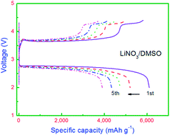
Finding stable electrolytes is essential to address the poor cycling capability of current rechargeable non-aqueous Li–O2 batteries. An optimized dimethyl sulfoxide (DMSO) based electrolyte using lithium nitrate (LiNO3) as the lithium salt has been first investigated for rechargeable Li–O2 batteries. The charge over-potential of Li–O2 batteries with LiNO3/DMSO electrolyte is 0.42 V lower than that of batteries with LiClO4/DMSO electrolyte. The Li–O2 batteries with LiNO3/DMSO electrolyte also showed excellent high C-rate performance and good cycling stability.


Introduction

Rechargeable Li–O2 batteries have been considered as one of the most promising candidates to meet today's stringent requirements as the power source for electric vehicles.1–3 The theoretical specific energy of the Li–O2 battery is 3505 W h kg−1, which is almost ten times higher than that of Li-ion batteries (387 W h kg−1).4 A typical rechargeable Li–O2 battery consists of an oxygen diffusion porous cathode, a lithium metal anode and an aprotic Li+ conducting electrolyte. The basic chemical reactions of Li–O2 batteries involve the formation of Li2O2 during the discharge process and the decomposition of Li2O2 during the charge process. Early studies of nonaqueous rechargeable Li–O2 batteries based on carbonate electrolytes showed extremely high charge–discharge over-potential and poor cycling stability. The intermediate species of oxygen reduction reaction (ORR), lithium superoxide, can react with those commonly used carbonate electrolytes and form significant amounts of undesirable by-products, leading to a serious challenge for developing high performance rechargeable Li–O2 batteries.5–7 Later, ether-based electrolytes attracted more attention, owing to their increased stability against lithium superoxide and high oxygen solubility.8,9 Li–O2 batteries with ether-based electrolytes showed high specific capacity and good cycling stability.10–12 However, they are still not completely stable in the Li–O2 battery system. By-products, such as Li2CO3, HCO2Li, CH3CO2Li and polyester, were found to have accumulated upon cycling.9

Recently, a novel dimethyl sulfoxide (DMSO) based electrolyte has been employed for Li–O2 batteries, exhibiting an excellent electrochemical performance owing to its remarkable stability against lithium superoxides, high Li+ conductivity and good oxygen diffusion.13–15 The presence of Li2O2 corroborated by in situ surface enhanced Raman spectroscopy (SERS) and X-ray diffraction (XRD) after many cycles demonstrated that DMSO-based electrolytes are highly suitable for rechargeable Li–O2 batteries.14 Furthermore, through the use of TiC as a stable cathode electrode material, the electrochemical performance of DMSO-based electrolyte outperformed the ether-based electrolyte.16 However, DMSO is not totally stable when in contact with Li foil anodes and was even replaced by LiFePO4 anode in some of recent published papers.14,17 Therefore, finding an appropriate strategy to stabilize the Li metal in DMSO is necessary for the development of Li–O2 batteries with DMSO-based electrolyte. Recently, Walker et al. demonstrated that a stable and protective solid-electrolyte interphase (SEI) layer can be formed on the Li anode surface by employing lithium nitrate (LiNO3) as the salt in N,N-dimethylacetamide (DMA) based electrolytes through the following reaction:18,19

2Li + LiNO3 → Li2O + LiNO2

As reported in Li–S batteries, the nitrate anion is capable of forming a protective SEI on Li anode, which can effectively block the transfer of electrons from the Li anode to soluble, long-chain polysulfides that are released from the sulfur cathode during cell operation.20,21 Inspired by this discovery, we consider that LiNO3 may also have the same effect on the stabilization of the Li/electrolyte interface in DMSO-based electrolyte for Li–O2 batteries.

Herein, the electrochemical performances of two DMSO-based electrolytes, LiClO4 in DMSO (LiClO4/DMSO) and LiNO3 in DMSO (LiNO3/DMSO), were investigated in rechargeable Li–O2 batteries. Interestingly, we found that Li–O2 batteries with a LiNO3/DMSO electrolyte showed significant lower charge over-potential (0.42 V) than those with LiClO4/DMSO electrolyte. The concentration of LiNO3 in the DMSO-based electrolyte was also optimized.

Experimental

Electrolyte preparation

Anhydrous dimethyl sulfoxide (DMSO) (>99.9%), LiClO4 (>99.99%) and LiNO3 (>99.99%) were purchased from Sigma-Aldrich. DMSO was distilled before use and LiClO4 and LiNO3 were dried under vacuum oven to remove moisture. n M LiClO4/DMSO (n = 0.1, 0.5, 1) or n M LiNO3/DMSO (n = 0.1, 0.5, 1, 1.5, 2) electrolyte was prepared in an argon-filled glove box.

Material characterization

The morphology of the discharge products were analyzed by field-emission scanning electron microscopy (FESEM, Zeiss Supra 55VP).

Li–O2 cell measurements

For the preparation of cathode electrodes, catalyst slurry was prepared by mixing carbon nanotubes (90 wt%), with poly(tetrafluoroethylene) (PTFE) (10 wt%) in iso-propanol. The mixture was coated onto a glass microfibre separator. After drying at 110 °C in a vacuum oven for 12 h, the cathode film was punched into discs with a diameter of 14 mm. The typical loading of the air electrode is about 0.5 mgcarbon cm−2. Swagelok type cell with an air hole (0.785 cm2) on the cathode side was used to investigate the battery performance. The Li–O2 batteries were assembled in an Ar filled glove box (Mbraun) with water and oxygen level less than 0.1 ppm. A lithium foil was used as the anode and was separated by a glass microfibre separator, soaked in as-prepared electrolyte. The cell was gas-tight except for the stainless steel mesh window that exposed the porous cathode film to the oxygen atmosphere. All the measurements were conducted in 1 atm dry oxygen atmosphere to avoid any negative effects of humidity and CO2. The galvanostatically charge–discharge performance was conducted on Neware battery tester at room temperature. Cyclic voltammetry (CV) was performed on the CHI 660E electrochemical station between 2.0 and 4.4 V at a scan rate of 0.05 mV s−1. Electrochemical impedance spectra (EIS) measurements were also performed using a CHI 660E electrochemical station in a frequency range of 100 kHz to 10 mHz.

Results and discussion

The electrochemical performances of Li–O2 batteries with two DMSO-based electrolytes were investigated in pure oxygen using carbon nanotubes (CNTs) as the cathode catalysts and lithium foil as the anode. The oxygen electrodes were made by coating the CNTs on glass fibre separators, which allows efficient oxygen diffusion through the electrode.22 The background linear sweep voltammetry (LSV) experiment carried out in oxygen atmosphere demonstrated that both DMSO-based electrolytes were very stable below 4.0 V (Fig. 1a). The electrolyte decomposition became serious only above 4.4 V, indicating that the electrochemical voltage windows of both DMSO-based electrolytes are suitable for Li–O2 battery operation. Cyclic voltammetry (CV) was employed to investigate the oxygen reduction reaction (ORR) and oxygen evolution reaction (OER) activities in the Li–O2 batteries with two DMSO-based electrolytes. Fig. 1b and c show the CV curves, which were measured using two different electrolytes. Both of them show strong reduction peaks during the first cathodic scan, indicating the good ORR activity of Li–O2 batteries with carbon based cathode catalysts.10,23–25 In the second and third scanning cycles, the CV curves show an obvious cathodic peak with lower peak intensity than that in the first cycle. During the subsequent anodic scan process, a strong OER peak can be observed at 3.9 V for the electrode with LiNO3/DMSO electrolyte. However, no oxidation peak can be observed below 4.0 V for the electrode with LiClO4/DMSO electrolyte. Furthermore, the anodic peak intensity of the electrode with LiNO3/DMSO electrolyte is much higher than that of the electrode with LiClO4/DMSO electrolyte. For the anodic scan process in the second and third cycle, the electrode with LiNO3/DMSO electrolyte still displays apparent oxidation peaks, demonstrating the good reversibility for OER. The CV measurement identified that the charge over-potential of OER in the Li–O2 battery system with LiNO3/DMSO electrolyte is much lower than that with LiClO4/DMSO electrolyte.
image file: c3ra47372d-f1.tif
Fig. 1 (a) LSV curves and (b and c) CV curves of Li–O2 batteries with two DMSO-based electrolytes at the scan rate of 0.05 mV s−1.

The galvanostatic charge–discharge measurements were further conducted to evaluate the electrochemical performances of Li–O2 batteries by curtailing the charge–discharge capacity to 1000 mA h g−1 at the current density of 200 mA g−1 as shown in Fig. 2. The Li–O2 battery with LiNO3/DMSO electrolyte showed the same discharge voltage plateau as the battery with LiClO4/DMSO electrolyte. However, the charge voltage plateau of the Li–O2 battery with LiNO3/DMSO electrolyte is only 3.74 V, which is much lower (0.42 V) than that of the battery with LiClO4/DMSO electrolyte. This means that the charge over-potential of the whole battery significantly decreased when changing the lithium salt from LiClO4 to LiNO3. The Li–O2 batteries with carbon black and Vulcan carbon as the cathode catalysts also showed reduced charge over-potential when using LiNO3/DMSO as the electrolyte (Fig. S1, ESI). The SEM images of the pristine, discharged and recharged electrodes with two DMSO-based electrolytes are shown in Fig. 3. After discharge, both electrodes were covered by the discharge product Li2O2. For both electrodes with two DMSO-based electrolytes, the morphology of Li2O2 consists of bundles of nanosheets. Some of them formed into toroidal structures, which is consistent with recent reports.16,24,26,27 All the discharge products were decomposed during the subsequent charge process. The SEM results confirm the formation and decomposition of Li2O2 during charge–discharge process. Previous report of Li–O2 battery using LiNO3/DMA as the electrolyte also showed similar charge voltage plateau, indicating that the charge voltage plateau of Li2O2 oxidation can be reduced to lower than 4.0 V during OER in a stable electrolyte system with LiNO3 as the electrolyte salt. Our results are consistent with the previous report, which means that LiNO3 salt plays an important role in rechargeable Li–O2 battery system with DMSO based electrolyte. The significant decrease of the charge voltage plateau in LiNO3/DMSO electrolyte compared with LiClO4/DMSO electrolyte should be due to the NO2/NO3 couple as a redox mediator in electron transfer from Li2O2 to the current collector, which acts as the electrocatalyst during the charge process, reducing the charge overpotential and facilitating the oxygen evolution reaction.18,19,28,29 The concentration of lithium salts in electrolyte also plays an important role in the cycling stability of Li–O2 batteries.30 Here, we further systematically studied the influence of the lithium salt concentration on the electrochemical performance of Li–O2 batteries with DMSO-based electrolyte. The cycling performances of Li–O2 batteries with n M LiClO4/DMSO electrolytes (n = 0.1, 0.5, 1) are shown in Fig. S2 (ESI). All three batteries showed similar cycling stability, indicating that the concentration of LiClO4 in DMSO-based electrolyte does not significantly affect the cycling performance. However, the cycling performance of Li–O2 batteries with n M LiNO3/DMSO electrolyte (n = 0.1, 0.5, 1, 1.5, 2) exhibited different cycling stability (as shown in Fig. 4). With the increasing concentration of LiNO3 in DMSO-based electrolyte, the stability of Li–O2 batteries became much better. The concentration of LiNO3/DMSO electrolyte above 1 M is necessary to maintain good cycling stability. High concentration of LiNO3 in the electrolyte can benefit to the formation of SEI layer on the surface of lithium anode and effectively suppresses the side reaction between DMSO and the lithium anode, which contributes to the improved cycling performance.


image file: c3ra47372d-f2.tif
Fig. 2 Charge–discharge voltage profiles of Li–O2 batteries by curtailing the capacity to 1000 mA h g−1.

image file: c3ra47372d-f3.tif
Fig. 3 SEM images of (a and b) pristine CNTs electrode, (c) after discharge to 2.7 V and (d) recharge to 4.5 V in LiClO4/DMSO electrolyte, and (e) after discharge to 2.7 V and (f) recharge to 4.5 V in LiNO3/DMSO electrolyte.

image file: c3ra47372d-f4.tif
Fig. 4 (a–e) Charge–discharge voltage profiles of Li–O2 batteries with LiNO3/DMSO electrolyte at different concentration by curtailing the capacity to 1000 mA h g−1 at the current density of 200 mA g−1. (f) The middle-value voltages of charge and discharge vs. cycle number.

The formation of SEI layer on the lithium anode in LiNO3/DMSO electrolyte is revealed by EIS measurements (Fig. S3, ESI). The EIS analysis was first performed on the symmetric Li/Li cells. The semicircle from high to medium frequency represents the SEI layer resistance as shown in Fig. S3a and b (ESI).31 In both symmetric cells with two electrolytes, the interfacial resistance continues to change during the 8 days storage. However, for the Li–O2 cells, the interfacial resistance became stable in LiNO3/DMSO electrolyte from the 3rd day, indicating a stable SEI layer was formed on the surface of lithium anode. The synergistic effect between LiNO3 and O2 on the formation of SEI on lithium anode demonstrates the promising application of LiNO3/DMSO electrolyte for Li–O2 batteries.

The cycle capabilities of the Li–O2 battery with 1.5 M LiNO3/DMSO electrolyte were further investigated at the current density of 200 mA g−1 in the voltage range of 2.0–4.4 V. Fig. 5a shows the voltage curves of the Li–O2 battery in the first five cycles. All the curves exhibit a similar charge voltage plateau at about 3.7 V, indicating the good reversibility of the Li–O2 battery with 1.5 M LiNO3/DMSO electrolyte. However, for the Li–O2 battery with 0.5 M LiClO4/DMSO electrolyte, the charge voltage plateau is higher than 4 V in the first cycle and continues to increase upon cycling. The capacity retention of Li–O2 battery with 1.5 M LiNO3/DMSO electrolyte is also much higher than the Li–O2 battery with 0.5 M LiClO4/DMSO electrolyte in the first five cycles. The long-term cycle stability of the Li–O2 battery with 1.5 M LiNO3/DMSO electrolyte was tested at a relatively high current rate (400 mA g−1). As shown in Fig. 6, the Li–O2 battery showed very good cycling performance, the charge voltage plateau under 4.0 V can still be observed after 50 cycles. No capacity fading was detected when curtailing the capacity to 1000 mA h g−1 in the voltage range of 2.0–4.6 V. The good cycling stability, high C-rate performance and low charge over-potential demonstrates that LiNO3/DMSO electrolyte is a promising electrolyte for Li–O2 batteries.


image file: c3ra47372d-f5.tif
Fig. 5 Cycling performance of Li–O2 batteries (a) with 1.5 M LiNO3/DMSO electrolyte and (b) with 0.5 M LiClO4/DMSO electrolyte at the current density of 200 mA g−1 in the voltage range of 2.0–4.4 V.

image file: c3ra47372d-f6.tif
Fig. 6 (a) Charge–discharge voltage profiles and (b) cycling performance of Li–O2 batteries with 1.5 M LiNO3/DMSO electrolyte at the current density of 400 mA g−1.

Conclusions

In summary, an optimized LiNO3/DMSO electrolyte was investigated for Li–O2 batteries. With the adding of LiNO3 salt, a stable SEI can be formed between lithium anode and DMSO-based electrolyte. Owing to the protective film generated on the lithium anode in the optimized electrolyte, improved battery performances have been achieved, including low charge over-potential, high C-rate performance and good cycling stability.

Acknowledgements

This project was financially supported by the Australian Research Council (ARC) through the ARC FT project (FT110100800).

Notes and references

  1. K. M. Abraham and Z. Jiang, J. Electrochem. Soc., 1996, 143, 1–5 CrossRef CAS PubMed.
  2. J. S. Lee, S. T. Kim, R. Cao, N. S. Choi, M. Liu, K. T. Lee and J. Cho, Adv. Energy Mater., 2011, 1, 34–50 CrossRef CAS.
  3. G. Girishkumar, B. McCloskey, A. C. Luntz, S. Swanson and W. Wilcke, J. Phys. Chem. Lett., 2010, 1, 2193–2203 CrossRef CAS.
  4. P. G. Bruce, S. A. Freunberger, L. J. Hardwick and J. M. Tarascon, Nat. Mater., 2012, 11, 19–29 CrossRef CAS PubMed.
  5. F. J. Li, T. Zhang and H. S. Zhou, Energy Environ. Sci., 2013, 6, 1125–1141 CAS.
  6. S. A. Freunberger, Y. H. Chen, Z. Q. Peng, J. M. Griffin, L. J. Hardwick, F. Barde, P. Novak and P. G. Bruce, J. Am. Chem. Soc., 2011, 133, 8040–8047 CrossRef CAS PubMed.
  7. B. Sun, B. Wang, D. W. Su, L. D. Xiao, H. Ahn and G. X. Wang, Carbon, 2012, 50, 727–733 CrossRef CAS PubMed.
  8. C. O. Laoire, S. Mukerjee, E. J. Plichta, M. A. Hendrickson and K. M. Abraham, J. Electrochem. Soc., 2011, 158, A302–A308 CrossRef CAS PubMed.
  9. S. A. Freunberger, Y. H. Chen, N. E. Drewett, L. J. Hardwick, F. Barde and P. G. Bruce, Angew. Chem., Int. Ed., 2011, 50, 8609–8613 CrossRef CAS PubMed.
  10. H. G. Jung, J. Hassoun, J. B. Park, Y. K. Sun and B. Scrosati, Nat. Chem., 2012, 4, 579–585 CrossRef CAS PubMed.
  11. T. Zhang and H. S. Zhou, Nat. Commun., 2013, 4, 2855 Search PubMed.
  12. Y. Chen, F. J. Li, D. M. Tang, Z. L. Jian, C. Liu, D. Golberg, A. Yamada and H. S. Zhou, J. Mater. Chem. A, 2013, 1, 13076–13081 Search PubMed.
  13. D. Xu, Z. L. Wang, J. J. Xu, L. L. Zhang and X. B. Zhang, Chem. Commun., 2012, 48, 6948–6950 RSC.
  14. Z. Q. Peng, S. A. Freunberger, Y. H. Chen and P. G. Bruce, Science, 2012, 337, 563–566 CrossRef CAS PubMed.
  15. M. J. Trahan, S. Mukerjee, E. J. Plichta, M. A. Hendrickson and K. M. Abraham, J. Electrochem. Soc., 2013, 160, A259–A267 CrossRef CAS PubMed.
  16. M. M. Ottakam Thotiyl, S. A. Freunberger, Z. Peng, Y. Chen, Z. Liu and P. G. Bruce, Nat. Mater., 2013, 12, 1050–1056 CrossRef CAS PubMed.
  17. Y. H. Chen, S. A. Freunberger, Z. Q. Peng, O. Fontaine and P. G. Bruce, Nat. Chem., 2013, 5, 489–494 CrossRef CAS PubMed.
  18. W. Walker, V. Giordani, J. Uddin, V. S. Bryantsev, G. V. Chase and D. Addison, J. Am. Chem. Soc., 2013, 135, 2076–2079 CrossRef CAS PubMed.
  19. V. Giordani, W. Walker, V. S. Bryantsev, J. Uddin, G. V. Chase and D. Addison, J. Electrochem. Soc., 2013, 160, A1544–A1550 CrossRef CAS PubMed.
  20. D. Aurbach, E. Pollak, R. Elazari, G. Salitra, C. S. Kelley and J. Affinito, J. Electrochem. Soc., 2009, 156, A694–A702 CrossRef CAS PubMed.
  21. X. Liang, Z. Y. Wen, Y. Liu, M. F. Wu, J. Jin, H. Zhang and X. W. Wu, J. Power Sources, 2011, 196, 9839–9843 CrossRef CAS PubMed.
  22. B. Sun, P. Munroe and G. X. Wang, Sci. Rep., 2013, 3, 2247 Search PubMed.
  23. Y. L. Li, J. J. Wang, X. F. Li, D. S. Geng, R. Y. Li and X. L. Sun, Chem. Commun., 2011, 47, 9438–9440 RSC.
  24. R. R. Mitchell, B. M. Gallant, C. V. Thompson and Y. Shao-Horn, Energy Environ. Sci., 2011, 4, 2952–2958 CAS.
  25. J. Xiao, D. H. Mei, X. L. Li, W. Xu, D. Y. Wang, G. L. Graff, W. D. Bennett, Z. M. Nie, L. V. Saraf, I. A. Aksay, J. Liu and J. G. Zhang, Nano Lett., 2011, 11, 5071–5078 CrossRef CAS PubMed.
  26. S. H. Oh, R. Black, E. Pomerantseva, J. H. Lee and L. F. Nazar, Nat. Chem., 2012, 4, 1004–1010 CrossRef CAS PubMed.
  27. J. J. Xu, Z. L. Wang, D. Xu, L. L. Zhang and X. B. Zhang, Nat. Commun., 2013, 4, 2438 Search PubMed.
  28. J. Uddin, V. S. Bryantsev, V. Giordani, W. Walker, G. V. Chase and D. Addison, J. Phys. Chem. Lett., 2013, 4, 3760–3765 CrossRef CAS.
  29. E. Nasybulin, W. Xu, M. H. Engelhard, Z. M. Nie, S. D. Burton, L. Cosimbescu, M. E. Gross and J. G. Zhang, J. Phys. Chem. C, 2013, 117, 2635–2645 CAS.
  30. F. J. Li, T. Zhang, Y. Yamada, A. Yamada and H. S. Zhou, Adv. Energy Mater., 2013, 3, 532–538 CrossRef CAS.
  31. J. M. Zheng, M. Gu, H. H. Chen, P. Meduri, M. H. Engelhard, J. G. Zhang, J. Liu and J. Xiao, J. Mater. Chem. A, 2013, 1, 8464–8470 CAS.

Footnote

Electronic supplementary information (ESI) available: Charge–discharge voltage profiles of Li–O2 batteries with Super-P carbon black and Vulcan XC-72 catalysts. Charge–discharge performances of Li-O2 batteries with LiClO4/DMSO electrolyte. See DOI: 10.1039/c3ra47372d

This journal is © The Royal Society of Chemistry 2014
Click here to see how this site uses Cookies. View our privacy policy here.