A novel synthetic strategy for bioinspired functionally graded nanocomposites employing magnetic field gradients

Tommaso Nardia, Yves Leterrier*a, Ayat Karimib and Jan-Anders E. Månsona
aLaboratoire de Technologie des Composites et Polymères (LTC), École Polytechnique Fédérale de Lausanne (EPFL), CH-1015, Lausanne, Switzerland. E-mail: yves.leterrier@epfl.ch; Fax: +41 21 69 35880; Tel: +41 21 69 34848
bLaboratoire de Physique de la Matière Complexe (LPMC), École Polytechnique Fédérale de Lausanne (EPFL), CH-1015, Lausanne, Switzerland

Received 15th November 2013 , Accepted 6th January 2014

First published on 7th January 2014


Abstract

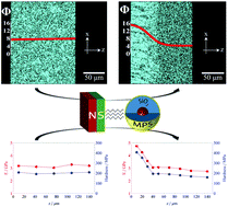
In order to mimic the complex architecture of many bio-materials and synthesize composites characterized by continuously graded composition and mechanical properties, an innovative synthetic strategy making use of magnetic field gradients and based on the motion of superparamagnetic Fe3O4@SiO2 core–shell nanoparticles is adopted. It is demonstrated that by lowering the viscosity of the system through particle functionalization, and increasing the magnetic force acting on the nanoparticles upon optimization of a simple set-up composed of two permanent magnets in repulsion configuration, the magnephoretic process can be considerably accelerated. Thus, owing to the magnetic responsiveness of the Fe3O4 core and the remarkable mechanical properties of the SiO2 shell, approximately 150 μm thick polymeric films with continuous gradients in composition and characterized by considerable increments in elastic modulus (up to ≈70%) and hardness (up to ≈150%) when going from particle-depleted to particle-enriched regions can be synthesized, even in times as short as 1 hour. The present methods are highly promising for a more efficient magnetic force-based synthesis of inhomogeneous soft materials whose composition is required to be locally tuned to meet the specific mechanical demands arising from non-uniform external loads.

Introduction

Many bio-composites such as bamboo,1 tissue interfaces,2,3 teeth4 and the majority of exoskeletal structures5,6 exemplify how tailoring and optimization of their mechanical performance rely strongly on the creation of specific hierarchical architectures and on the accurate spatial distribution of readily available reinforcing elements. It has been shown, for example, how mollusk shells improve their resistance to contact damage and layer delamination and provide a barrier to crack propagation through a smart spatial design of elastic moduli, which undergo approximately 40% gradual changes between intercrystalline soft organic layers and stiff ceramic crystallites.7 Over millions of years of evolution, nature has developed complex and non-uniform structures that perform extremely well under ambient loading conditions. Mimicking such performance constitutes one of the most ambitious goals in the engineering of artificial composites.

Functionally graded materials (FGMs) provide an artificial approach to reproducing the locally varying compositions encountered in bio-composites, as well as the smooth transitions at the interfaces between their components. Besides exhibiting locally varying mechanical properties,8–10 FGMs may combine different and apparently incompatible features within the same structure, giving rise to a variety of unusual, high-impact properties, such as spatially varying electronic performances,11 super hardness,12 graded refractive indexes,13 improved wear resistance and efficient residual stress distribution.14–16 Depending on the desired gradient morphology and on the nature of the materials employed, techniques such as chemical vapor deposition (CVD),17 powder densification,18 thermal spraying,19 solvent-welding,20 centrifugal casting, electrodeposition (EPD) or self-driven transport-based processes21–23 may be used. However, these may either be multi-step processes, often requiring the use of computer-aided automated systems and making use of expensive apparatuses and/or complex synthetic strategies, or have strong limitations when parts with complex geometries are required. Moreover, many such processes are inappropriate to soft polymeric materials. An alternative approach relies on transport-based processes arising from magnetic forces, although these have so far received little attention in the literature.24 The main forces acting on a magnetic particle with radius r immersed in a fluid under the influence of a magnetic field are the magnetic force, [F with combining macron]m, and the drag force, [F with combining macron]d. [F with combining macron]m is due to the gradient of the applied magnetic flux density, [B with combining macron], and the induced magnetic moment [m with combining macron] of the particle (eqn (1)),25 whereas [F with combining macron]d derives from the viscous drag exerted by the suspending medium (with viscosity η) on the moving particle, and is a consequence of the velocity difference, Δ[v with combining macron], between the particle and the fluid (eqn (2)).26

 
image file: c3ra46731g-t1.tif(1)
 
[F with combining macron]d = 6πηrΔ[v with combining macron] (2)

As [F with combining macron]m and [F with combining macron]d oppose each other, the particle velocity will increase with the gradient of [B with combining macron] and decrease with η.

In this study, we investigate the basic principles underlying the motion of superparamagnetic Fe3O4@SiO2 core@shell nanoparticles in an UV-curable hyperbranched polymeric matrix (HBP) under the effect of magnetic field gradients, proposing practical strategies to efficiently increase [F with combining macron]m and reduce η. Analyses of the gradient formation process and of the resulting graded mechanical properties are divided into four sections. First, we characterize the particle concentration gradients by means of SEM analyses. Second, we focus on the computation of the magnetic force exerted by different arrangements of permanent magnets on Fe3O4@SiO2 nanoparticles and we relate these analytical results with the experimentally observed gradient morphologies. Third, we analyze the viscosity of two different classes of uncured nanoparticulate systems based on the HBP matrix and containing either untreated Fe3O4@SiO2 nanoparticles or MPS-functionalized Fe3O4@SiO2 nanoparticles (see ESI for nanoparticle characterization), and we directly relate the observed trends in viscosity to considerations on the effectiveness of the gradient formation process. Finally, the gradients in Young's modulus and in hardness of the synthesized graded materials are assessed by means of nanoindentation tests, after UV-curing.

Such a synthetic procedure efficiently condenses into a one-step process the creation of non-uniform materials, whose design not only enhances the mechanical characteristics, as encountered in some biogenic composites,7 but also conveniently limits the use of reinforcing elements to those regions where they are most needed. Although these results are specific to the materials investigated, the underlying synthetic principles have the potential to be applied to many types of polymeric nanocomposites.

Experimental

Materials

Iron(III) acetyacetonate (Fe(acac)3, 99+%) and benzyl ether (99%) were purchased from Acros. Oleylamine (Tech.70%), polyoxyethylene(5)nonylphenyl ether (Igepal CO-520), 3-(trimethoxysilyl)propyl methacrylate (MPS, 98%), ethanol (≥99.5%) and the epoxy embedding medium kit were purchased from Aldrich. Cyclohexane (p.A.) was purchased from Applichem. Ammonia solution (25% min) and tetraethyl orthosilicate (TEOS, ≥99%) were purchased from VWR and Merck, respectively. The hyperbranched polyester acrylated oligomer (HBP, commercial name CN2302) was purchased from Sartomer, whereas the photo-initiator (Lucirin TPO) was purchased from BASF. All products were used as received without any further purification. Permanent magnets were block NdFeB (Neodymium Iron Boron-N42 grade) magnets purchased from Supermagnete. The structure holding the two permanent magnets in repulsion was made in austenitic steel.

Synthesis of bare and coated Fe3O4 nanoparticles

The synthetic procedure for Fe3O4 nanoparticles and Fe3O4@silica core–shell nanoparticles has been reported in a previous publication.27 MPS-functionalized core–shell nanoparticles were synthesized analogously to non-functionalized ones, with the only difference that 24 h after the addition of TEOS, 3-(trimethoxysilyl)propyl methacrylate was added into the reaction flask in a quantity around 1/14 of the TEOS amount.

Preparation of nanocomposites

As described earlier,27 the photo-initiator was first dissolved in the HBP in a 6 wt% fraction and subsequently the selected amount of core–shell nanoparticles was added. A certain amount of as-prepared nanocomposites were placed between two UV-transparent polystyrene sheets (16 mm × 16 mm × 0.3 mm, made by hot pressing polystyrene beads) kept at a distance of 150 μm by two plastic spacers (16 mm × 3 mm × 0.15 mm) which ensured a constant thickness of the final polymeric films. The polymerization process was performed irradiating the samples from both sides using two identical 200 W mercury bulb UV lamps (OmniCure 2000, Exfo, Canada). Using a calibrated radiometer (Silver Line, CON-TROL-CURE, Germany), the measured UV-A light intensity on the sample surface ensured by each lamp was around 190 mW cm−2. Small variations in the final thickness of the films were not excluded due to differences in mechanical properties and polymerization shrinkage. To analyze the nanoparticles distribution before and after the application of the magnetic field, the films were first embedded in an epoxy medium in order to guarantee their dimensional stability and subsequently cut with a diamond wire cutting machine to expose their cross-sectional area.

Methods

Infrared spectrometry was performed using a Perkin Elmer Spectrum One MIR (600–4000 cm−1) with an ATR accessory.

Embedded samples were cut using a Well Diamond Wire Saw, polished with a Struers Dap-V polishing machine and made conductive for SEM analysis upon deposition of a 20 nm carbon layer with a Cressington 108 carbon/a carbon-coater. The concentration gradient was investigated analyzing the Si content by SEM-EDX analysis using a FEI XLF-30 FEG at an accelerating voltage Vacc of 13 kV and at a constant working distance (11 mm) and spot size (4). An average elemental composition of the samples was obtained by data collection over a 150 μm × 120 μm-sized window.

Nanoindentation measurements were performed on the transverse cross-sectioned samples using a Nano Indenter XP™ (MTS Nano Instruments) with a three-sided diamond Berkovich indenter. Different series of tests were conducted with and without continuous stiffness measurements (CSM) mode. Under CSM engagement, indenter was operated at the tip frequency of 45 Hz, harmonic displacement of 2 nm, and constant nominal strain rate of 0.05 s−1. For tests with the CSM mode off, multiple steps of cyclic loading approach were applied to capture load-displacement hysteresis due to viscoelastic effects. For all tests the indenter tip approached the surface from a distance of 1000 nm at a rate of 10 nm s−1, and the maximum penetration depth into the sample was set to 1000 nm. Hardness and Young's modulus were determined using the Oliver and Pharr's analysis method28 and assuming a Poisson's ratio of 0.35. To provide a simple comparison, the reported values of hardness and Young's modulus correspond to a penetration depth of 1000 nm into the samples.

Results and discussion

Graded morphologies

In order to facilitate the comparison between different samples and testing conditions, all the SEM-EDX images showing the results of the synthetic process are summarized in a single table (Fig. 1). Each panel shows the Si content along the cross-section of approximately 150 μm thick nanoparticulate UV-cured films based on the acrylated hyperbranched polymeric matrix (HBP). Prior to curing, polymeric films containing 1 vol% or 8 vol% of homogeneously distributed Fe3O4@SiO2 nanoparticles (Fig. 1a1–f1) were placed under the effect of the magnetic field gradient generated either by a single magnet or by two magnets in repulsion configuration (i.e. with the magnetizations opposing each other). When only one magnet was employed, the distance z from its surface to the closest edge of the film was chosen in order to maximize the z-component of [F with combining macron]m (Fig. 2a) and accelerate the gradient formation process along the z-direction (see Section 2.2). Similarly, when two magnets in repulsion configuration were used, their relative distance d as well as the distance z between one of them and the closest edge of the nanoparticulate film (Fig. 2b) were optimized for the maximization of the z-component of [F with combining macron]m (see Section 2.2).
image file: c3ra46731g-f1.tif
Fig. 1 Cross-sectional SEM-EDX spectral images showing the Si content of different samples (composition indicated on the left side of the table). Samples have been under the influence of the magnetic force generated by a single magnet (blue) and two magnets in repulsion configuration (red) for the time indicated at the top of the table. The superimposed curves indicate the nanoparticle volume fractions Φ (×100) all along the sample cross-sections.

image file: c3ra46731g-f2.tif
Fig. 2 Schematic representation of the nanoparticulate film (red) placed at a distance z from a single magnet (a) and from one of two facing magnets (b). In (b) the two magnets are positioned at a distance d between each other.

The gradient morphology was then observed after 1 hour (Fig. 1a2–f2) and 24 hours (Fig. 1a3–f3) from the initial application of [F with combining macron]m. Even though the size of the synthesized samples (1 cm × 1 cm × 150 μm, see ESI) is limited by the employed lab-scale set up, it is believed that bigger sample sizes could be easily attained in industrial applications, for which the utilization of stronger magnets would not be precluded. While not being able to achieve the same grading capability of layer-by-layer techniques,20 which although require a more costly and time consuming preparation, it is evident that the proposed technique enables the creation of rather steep concentration profiles within reasonable amounts of time. Moreover, it should be pointed out that the proposed process makes use of nanofillers that, being 2–3 orders of magnitude smaller than those found in the great majority of graded polymeric composites synthesized through different field-based processes (e.g. centrifugal casting29), are intrinsically affected by a rather weak driving force.

Magnetic force

This section analyses the influence of the magnetic force intensity on the gradient formation process. In particular, we compute the magnetic forces exerted by three different arrangements of permanent magnets on the utilized superparamagnetic Fe3O4@SiO2 nanoparticles, which have been previously morphologically and magnetically characterized.27 The first case describes a single magnet with a positive magnetization; the second one considers two magnets in repulsive configuration (the top magnet having negative magnetization and the other a positive one), whereas the third involves two magnets in attractive configuration (both with a positive magnetization). All the values for the magnetic force reported in the following pertain to a single Fe3O4 nanoparticle (with radius = 2.85 nm), which constitute the magnetic domain of the core–shell particles (with radius = 12.8 nm) employed as fillers. As can be seen in Fig. 3, the highest values of the z-component of [F with combining macron]m acting on a Fe3O4 nanoparticle are encountered when two magnets in repulsion configuration are employed and, specifically for the studied materials, when d = 1.6 cm and z = 0 cm (Table 1). The corresponding highest values of the z-component of [F with combining macron]m are encountered at z = 2 mm for the single magnet case, whereas at d ≥ 80 mm and z = 0 mm for the case of two magnets in attraction configuration. In particular, the highest value of the z-component of [F with combining macron]m generated by two magnets in repulsion exceeds by 24% the maximum force generated either by a single magnet or by two magnets in attraction configuration. The method for obtaining these values is discussed in greater details in the ESI.
image file: c3ra46731g-f3.tif
Fig. 3 Trend of the highest values of the z-component of the magnetic force [F with combining macron]m exerted on a single Fe3O4 nanoparticle as a function of the distance d between the magnets (z = 2 mm for the single magnet case, z = 0 mm for both the ‘two magnets’ configurations).
Table 1 Highest computed z-component of the magnetic force acting on a single Fe3O4 nanoparticle with corresponding values of the parameters d and z for three different configurations of permanent magnets
Configuration d/mm z/mm [F with combining macron]m/N
Single magnet 2 1.914 × 10⁻¹⁹
2 magnets in repulsion 16 0 2.378 × 10⁻¹⁹
2 magnets in attraction ≥80 0 1.914 × 10⁻¹⁹


Following the results of the computational studies, only the effects of the magnetic forces generated by a single magnet and by two magnets in repulsion configuration were further investigated. When the polymeric matrix is filled with 8 vol% of untreated Fe3O4@silica nanoparticles (HBP + 8 vol% Fe3O4@silica), the composition remains almost unchanged after 1 hour under the effect of the field generated by the single magnet (Fig. 4a 1 h), whereas a gradient is already noticeable when two magnets in repulsion are employed (Fig. 4b 1 h). After 24 hours, a continuous compositional gradient is developed for both cases (Fig. 4a and b 24 h), but ranging from 13 to 6 vol% if two magnets in repulsion are used and from 11.5 to 6.5 vol% when only one magnet is used. In order to be able to compare the developments of the compositional gradient between the various samples, the curves showing the particle volume fraction as a function of the position z were extrapolated to a fixed length of 150 μm and the average distance traveled (ADT) by the nanoparticles was defined as

 
image file: c3ra46731g-t2.tif(3)
where Φi is the volume fraction of nanoparticles at the position i along the thickness of the sample and the subscripts (t and 0) represent the time spent under the influence of the external magnetic field. The as-calculated ADT points were fitted with a negative exponential function of the type y = a(1 − exp(−kx)).


image file: c3ra46731g-f4.tif
Fig. 4 (a and b) Concentration profiles of Fe3O4@silica nanoparticles as a function of the position along the sample cross-section for the single magnet case and the case of two magnets in repulsion configuration, evaluated at different times. (c) Calculated ADT (eqn (3)) as a function of the time spent under the influence of the externally applied magnetic field (the films span the range from z = 0 to z = 150 μm).

Making use of this definition, we can see (Fig. 4c) that the gradient created in 24 hours with a single magnet can be generated with two magnets in repulsion within half of the time. In general, for both systems the gradient undergoes a continuous development during the whole 24 hours, but turns out to be significantly faster when two magnets in repulsion are used.

As a matter of fact, the magnitude of the applied magnetic force is directly reflected both on the steepness of the maximum achievable gradient and on the speed of the gradient formation process. The magnetic force increment generated by a simple set-up of permanent magnets placed in repulsion configurations can not only reduce the time needed to attain a certain gradient, but can effectively induce nanoparticle motion even at higher local viscosities, giving rise to gradients unattainable with the employment of a single magnet.

Drag force

This section investigates the effect of the viscosity of the nanoparticulate suspensions on the gradient development process. In particular, two systems filled with different amounts of non-functionalized and MPS-functionalized Fe3O4@silica nanoparticles are studied and compared. Ruckenstein et al. already clarified the importance of surface treatment on the dispersing ability of nanoparticles in polymeric media.30,31 Here, rheological tests (Fig. 5) show that for all the studied systems acrylation of the particles surface with MPS has a significant effect on the viscoelastic properties of the composite prior to UV-curing. Following the trend previously reported by Geiser et al.,32 systems containing acrylated nanoparticles always evidence a much lower complex viscosity than that of the suspensions filled with non-functionalized particles (Fig. 5), due to a strong reduction of elastic effects (η′′). This is most likely due to H-bonding suppression and to lower particle–polymer interactions. In particular, the complex viscosity and elastic contribution of the system filled with 8 vol% of Fe3O4@silica–MPS nanoparticles are, at ω = 0.1 rad s−1, 6 and 40 times lower, respectively, than those of the suspension containing the same amount of non-acrylated particles.
image file: c3ra46731g-f5.tif
Fig. 5 Complex viscosity, η*, and viscous and elastic contribution, η′ and η′′, respectively, of the nanoparticulate-composites filled with non-functionalized Fe3O4@silica nanoparticles (a) and with MPS-functionalized Fe3O4@silica nanoparticles (b) as a function of frequency and loading level.

In order to compare the effect of different drag forces we investigated the development of the concentration gradient, under the influence of the same magnetic field generated by two magnets in repulsion configuration, for the two systems containing non-functionalized and MPS-functionalized Fe3O4@silica nanoparticles. Suspensions containing 1 vol% of non-functionalized nanoparticles (Fig. 6a1) developed a gradient spanning from 4.5 to 0.8 vol% after 1 hour and from 5.5 to 0.2 vol% after 24 hours. The small decrease in viscosity characterizing the systems filled with 1 vol% of Fe3O4@silica–MPS nanoparticles (Fig. 6b1) compared to those filled with non-silanized particles was sufficient to induce a faster process, enabling the formation of a gradient ranging from 6 to 0.7 vol% after 1 hour and from 7.2 to 0.2 vol% after 24 hours.

It should be pointed out that during the magnetophoretic process the characteristic velocities of Fe3O4@silica particles, covering distances in the order of some tens of microns in time frames in the order of hours, can be estimated to be at least one order of magnitude smaller than those experienced by the nanoparticles in the rheological test. In light of this, it is reasonable to assume that a more precise evaluation of the viscosity experienced by the magnetic nanofiller during the magnetophoretic process should be done at angular frequencies lower than 0.1 rad s−1, which is however the limit imposed by the instrument. At such low values of ω, given that nanocomposites containing MPS-functionalized nanoparticles exhibit a slight shear thinning behavior, whereas systems containing non-functionalized Fe3O4@silica nanoparticles evidence a non-linear decrease of the complex viscosity with increasing applied angular frequency, the difference in η* would most likely be much higher than that evidenced at 0.1 rad s−1. This would explain why MPS surface treatment has such an effect on the speed of the magnetophoretic process and why, even at particle volume fractions as low as 1%, the gradient formation process (Fig. 6c1) reaches a steady state in more than 10 hours for systems containing non-functionalized particles and within 3 hours for those filled with MPS-treated ones.

Upon going towards higher loading levels the different behaviors of the suspensions filled with untreated and MPS-treated nanoparticles are much more pronounced. When HBP is loaded with 8 vol% of non-functionalized particles (Fig. 6a2), the nanoparticle distribution remains almost unchanged after 1 hour under the effect of the magnetic field, whereas a very mild concentration gradient, ranging from 13 to 6 vol%, is generated after 24 hours. On the contrary, when the HBP is loaded with 8 vol% of Fe3O4@silica–MPS nanoparticles (Fig. 6b2), the gradient already spans from 14.5 to 4.5 vol% after 1 hour and from 15 to 4 vol% after 24 hours. Moreover, a steady state is reached after 10 hours for the suspensions containing 8 vol% of non-functionalized particles, whereas the gradient formation process is almost complete within 1 hour if Fe3O4@silica–MPS nanoparticles are employed (Fig. 6c2). As a matter of fact, the viscosity control through particle surface treatment turns out to be a fundamental aspect to take into account for a fast gradient development process, becoming more and more important upon going towards high particle loading fractions.

Finally, a good correlation between the average velocity (vexp) of the particle calculated from their average distance travelled (ADT, eqn (3)) during the whole 24 hours and the velocity (vcalc) deduced from the analytical equations describing [F with combining macron]m (eqn (1)) and [F with combining macron]d (eqn (2)) was obtained, in spite of simplified hypotheses (Table 2). For the evaluation of [F with combining macron]d, the viscous viscosity η′ was inserted in eqn (2). The difference between experimental and calculated values is attributed to the viscoelastic nature of the fluid, which leads the expression for the viscous drag force to depart from the classical result (eqn (2)),33 and to other effects such as aggregation and dipole interactions.34

Table 2 Experimental velocities (vexp) of the different nanofillers as calculated from their ADT (eqn (3)) during 24 hours and their velocities (vcalc) calculated starting from the analytical expressions for [F with combining macron]m and [F with combining macron]d. The viscous viscosities η′ of the different systems are also indicated
Φ 0.01 0.01 0.08 0.08 0.08 0.08
a Two magnets in repulsion configuration.b Single magnet configuration.
Surface MPS MPS MPS
Configuration 2 Ma 2 Ma 1 Mb 2 Ma 1 Mb 2 Ma
η′ (Pa s) 0.93 0.75 6.38 6.38 1.55 1.55
vexp (μm h−1) 1.41 1.39 0.28 0.36 0.61 0.96
vcalc (μm h−1) 1.91 2.36 0.22 0.28 0.92 1.14


Graded Young's modulus and hardness

To correlate the local particle volume fraction with the corresponding mechanical properties, indentations were performed all along the cross-section of the ≈150 μm-thick samples (Fig. 7). In light of the better results obtained during the gradient formation process, only the samples filled with MPS-treated nanoparticles were tested.

Increments in Young's modulus and hardness with respect to the pure HBP (E = 2.06 GPa, H = 109 MPa) are already noticeable when 1 vol% of Fe3O4@SiO2–MPS nanoparticles are homogeneously dispersed in the polymeric matrix (E = 2.31 GPa, H = 131 MPa), becoming more evident when 8 vol% of Fe3O4@SiO2–MPS nanoparticles are used (E = 3.17 GPa, H = 203 MPa).

When uncured nanosuspensions filled with 1 vol% of homogeneously distributed Fe3O4@SiO2–MPS nanoparticles are left under the effect of the magnetic field gradient generated by two magnets in repulsion configuration, remarkable variations in elastic modulus (+41%) and hardness (+60%) when going from particle-depleted to particle-enriched regions of the cured composites are noticeable already after 1 hour. Remaining the gradient morphology almost unaltered (Fig. 6b1), these variations remain almost unchanged (+39% in modulus and +65% in hardness) after 24 hours from the initial application of the magnetic field gradient. Variations of mechanical properties become more evident when going towards higher particle volume fractions. As a matter of fact, outstanding gradations in elastic modulus (up to +56%) and hardness (up to +125%) are encountered when moving from particle-depleted to particle-enriched zones in films filled with 8 vol% of Fe3O4@SiO2–MPS nanoparticles and having been under the effect of the magnetic field gradient for just 1 hour. Following the development of the gradient morphology (Fig. 6b2), these variations become even more important after 24 hours of magnetic field gradient application, reaching values of +70% for the modulus and +152% for the hardness. Not only the synthesized graded materials evidence considerable variations in mechanical properties within their structure, but they also show regions characterized by much higher moduli and hardness compared to the corresponding homogeneous counterparts (Fig. 8). In particular, 1 hour of magnetic field gradient application gives rise to a substantial local increase in modulus (by 31%) and hardness (by 50%) compared to the corresponding values of the nanocomposites containing 1 vol% of homogeneously distributed Fe3O4@SiO2–MPS nanoparticles. While the increment in elastic modulus remains unchanged after 24 hours of magnetic field gradient application (+31%), hardness reaches a value 59% greater than that of the homogeneous nanocomposite. When nanosuspensions filled with 8 vol% of homogeneously distributed Fe3O4@SiO2–MPS nanoparticles are left under the effect of the magnetic field, the increments in elastic modulus and hardness compared to the corresponding homogeneous samples are in the order of 32% and 70%, respectively, after 1 hour, and of 50% and 101%, respectively, after 24 hour. As a matter of fact, the local concentration of particles within a specific region of the composite not only gives rises to continuously graded materials presenting substantial variations in elastic modulus and hardness within their body and characterized by smooth transitions between mechanically different areas, but also represents an efficient strategy to rationalize the distribution of reinforcing elements, locally maximizing the stiffness and the hardness in nanocomposites.


image file: c3ra46731g-f6.tif
Fig. 6 Concentration profiles of non-functionalized (a) and MPS-functionalized (b) Fe3O4@silica nanoparticles as a function of the position along the sample cross-section. Samples have been under the influence of the magnetic field gradient generated by two magnets placed in repulsion configuration at a distance d = 1.6 cm (c). Calculated ADT (eqn (3)) as a function of the time spent under the influence of the externally applied magnetic field.

image file: c3ra46731g-f7.tif
Fig. 7 Elastic modulus and hardness as a function of the position z along the film thickness for the formulations containing MPS-treated NPs prior to (●) and after 1 (▲) and 24 hours (■) from the application of the magnetic field gradient generated by two magnets in repulsion configuration.

image file: c3ra46731g-f8.tif
Fig. 8 Histograms showing the enhancement of elastic moduli and hardness of the cured nanocomposites filled with 1 vol% and 8 vol% of Fe3O4@SiO2–MPS nanoparticles. For the samples which have been under the effect of the magnetic field gradient, the minimum and maximum elastic moduli and hardness (i.e. corresponding to the values at the opposing edges of the film) are displayed. The green dashed line refers to the pure HBP.

Even though it is not the goal of this work to deepen the analysis on the mechanics of the synthesized nanocomposites, useful informations can still be deduced upon application of appropriate model describing the experimental behavior of heterogeneous materials. Upper and lower bounds models for the elastic modulus of composites are usually described by means of the classical rule of mixtures (RoM, eqn (4)) and the inverse rule of mixtures (eqn (5))

 
E = ΦENP + (1 − Φ)EHBP (4)
 
E = [Φ/ENP + (1 − Φ)/EHBP]−1 (5)
where E, ENP and EHBP represent the values for the elastic moduli of the composite, of Fe3O4@SiO2–MPS nanoparticles and of HBP, respectively, and Φ is the volume fraction of core–shell particles. The elastic modulus of Fe3O4@SiO2–MPS nanoparticles was assumed to be the same as that of SiO2 nanoparticles produced via sol–gel method, and was taken equal to 20 GPa (Zhang et al.35 reported a value of 18 GPa). The Halpin–Tsai model (eqn (6))36,37 is also generally applied to random or nearly random distributions of reinforcements arranged in a matrix, and takes the form:
 
image file: c3ra46731g-t3.tif(6)
where β is
 
image file: c3ra46731g-t4.tif(7)
and ξ is a ‘structure’ parameter, accounting for the filler geometry and aspect ratio. The fact that experimental data are well fitted by the classical rule of mixtures, which does not take into account the discontinuous nature of the particle assembly and the particle–matrix interplay, indicates a strong interaction between particles and dispersing matrix. The best fitting using the Halpin–Tsai model (Fig. 9a) was obtained with ξ = 34, indicating that, most likely due to interparticle magnetic attractions, the nanoparticles give rise to distributions with high aspect ratios38 aligning themselves along preferential directions (i.e. the direction of the magnetic field gradient).


image file: c3ra46731g-f9.tif
Fig. 9 Young's modulus (a) and hardness (b) of nanocomposites as a function of their nanoparticle volume fraction. Dots represent experimental data whereas lines refer to the indicated models.

As for the elastic modulus, upper and lower bounds models describing the hardness of the synthesized nanocomposites can be represented by the classical rule of mixtures (RoM, eqn (8))39 and the inverse rule of mixtures (eqn (9)):

 
H = ΦHNP + (1 − Φ)HHBP (8)
 
H = [Φ/HNP + (1 − Φ)/HHBP]−1 (9)
where H, HNP and HHBP represent the hardness values of the composite, of core–shell particles (taken equal to that of silica, i.e. 2800 MPa)40 and of HBP, respectively, and Φ is the volume fraction of core–shell particles. In order to account for the discontinuous nature of the reinforcing phase, in the present work a yielding model for the hardness was used41
 
image file: c3ra46731g-t5.tif(10)
where the fractional term in the right-hand-side describes the change of effective particle cross-section as a function of particle fraction Φ, B is an interface interaction parameter and A is a shape parameter associated with packing features of reinforcing particles:
 
image file: c3ra46731g-t6.tif(11)
where Φ* = 0.64 and ψ* = 0.842 are the random packing volume fraction for spheres, and random packing area fraction for disks, respectively,42 giving A = 1.9976 ≈ 2. Eqn (10) was fitted to the experimental data with adjustable parameter B. The result shown in Fig. 9b was obtained with B = 11.3, which is the highest value for B among those reported in former studies of particulate composites.41,43 The high value of B undeniably indicates the presence of strong interactions at the particle–polymer interface, most probably arising from the covalent linkages forming between acrylic groups present at the particle surface and in the polymer upon UV-curing.

Analyses of the nanoindentation tests seem to indicate efficient bond formation between the nanoparticles and the acrylated matrix, further enhancing the intrinsic improvement of characteristics deriving from the inclusion of the nanofiller. Further studies to evaluate the effect of particle surface treatment on the mechanical properties of the resulting composites are under way.

Conclusions

The synthetic approach presented here provides guidance toward a smarter design of soft materials characterized by a tunable degree of local reinforcement. By filling a polymeric matrix with core–shell nanoparticles comprising a magnetic core and a silica shell with tailored surface, the magnetic responsive filler is concentrated in specific regions of the composite upon application of magnetic field gradients, ending up with non-uniform structures characterized by graded mechanical properties. It is shown how the gradient formation process is strongly dependent on both the applied magnetic force and the viscosity of the nanoparticulate suspension. In particular, it is demonstrated how the use of a simple set-up composed of two block magnets in repulsion configuration can increase the force applied on the magnetic filler by 24% compared to that generated by a single magnet, and how functionalization of the particle surfaces with an acrylated silane leads to a 6-fold decrease in the low shear rate complex viscosity of the nanosuspensions. Both strategies showed to be fundamental to accelerate the gradient formation process and achieve gradient morphologies otherwise unattainable. The as-synthesized materials exhibit continuous gradations in mechanical properties and show remarkable increments in elastic modulus (up to ≈70%) and hardness (up to ≈150%) when going from particle-depleted to particle-enriched regions, even after magnetic field gradient application times as short as 1 hour.

Not only the proposed strategy merges into a single-step process the synthesis of graded structures able to maximize the reinforcing role of the filler and rationalize its utilization, but intrinsically adds functionality to the resulting nanocomposite, letting foresee interesting applications in fields such as those of magnetic sensors and actuators. In addition, owing to the multifunctionality of the core–shell filler, the applicability of the process could be extended well beyond that of bio-mimicking structures, opening up new paths to the efficient synthesis of materials with graded electrical or optical properties.

Acknowledgements

The authors acknowledge the Swiss National Science Foundation (project 200020_144396) for financial support. Sincere acknowledgements also to Manuel Bianco for his help on the construction of the permanent magnet set-up, to Danièle Laub and Colette Vallotton (CIME-EPFL) for their help on the preparation of the samples for the SEM, and to Christopher J. Plummer (LTC-EPFL) for the fruitful scientific advices.

References

  1. A. K. Ray, S. K. Das, S. Mondal and P. Ramachandrarao, J. Mater. Sci., 2004, 39, 1055 CrossRef CAS.
  2. J. E. Phillips, K. L. Burns, J. M. Le Doux, R. E. Guldberg and A. J. García, Proc. Natl. Acad. Sci. U. S. A., 2008, 105, 12170 CrossRef CAS PubMed.
  3. A. G. Mikos, S. W. Herring, P. Ochareon, J. Elisseeff, H. H. Lu, R. Kandel, F. Schoen, M. Toner, D. Mooney, A. Atala, M. E. Van Dyke, D. Kaplan and G. Vunjak-Novakovic, Tissue Eng., 2006, 12, 3307 CrossRef CAS PubMed.
  4. A. R. Studart, Adv. Funct. Mater., 2013, 23, 4423 CrossRef CAS.
  5. H. Yao, M. Dao, T. Imholt, J. Huang, K. Wheeler, A. Bonilla, S. Suresh and C. Ortiz, Proc. Natl. Acad. Sci. U. S. A., 2010, 107, 987 CrossRef CAS PubMed.
  6. C. Hedegaard, J. Mollus. Stud., 1997, 63, 369 CrossRef PubMed.
  7. H. Moshe-Drezner, D. Shilo, A. Dorogoy and E. Zolotoyabko, Adv. Funct. Mater., 2010, 20, 2723 CrossRef CAS.
  8. S. Suresh and A. Mortensen, Fundamentals of Functionally Graded Materials, Maney, Leeds, UK, 1998 Search PubMed.
  9. S. Suresh, Science, 2001, 292, 2447 CrossRef CAS PubMed.
  10. P. J. Hogg, Science, 2006, 314, 1100 CrossRef CAS PubMed.
  11. E. D. Wachsman and K. T. Lee, Science, 2011, 334, 935 CrossRef CAS PubMed.
  12. M. Riabkina-Fishman, E. Rabkin, P. Levin, N. Frage, M. P. Dariel, A. Weisheit, R. Galun and B. L. Mordike, Mater. Sci. Eng., A, 2001, 302, 106 CrossRef.
  13. G. Zuccarello, D. Scribner, R. Sands and L. J. Buckley, Adv. Mater., 2002, 14, 1261 CrossRef CAS.
  14. U. Schulz, M. Peters, Fr.-W. Bach and G. Tegeder, Mater. Sci. Eng., A, 2003, 362, 61 CrossRef.
  15. V. Birman and L. W. Byrd, Appl. Mech. Rev., 2007, 60, 195 CrossRef.
  16. R. K. Singh, D. R. Gilbert, S. Harkness and D. G. Lee, Science, 1996, 272, 396 CAS.
  17. J. L. Maxwell, M. Boman, R. W. Springer, A. Nobile, K. DeFriend, L. Espada, M. Sandstrom, D. Kommireddy, J. Pegna and D. Goodin, Adv. Funct. Mater., 2005, 15, 1077 CrossRef CAS.
  18. M. Belmonte, J. Gonzalez-Julian, P. Miranzo and M. I. Osendi, Acta Mater., 2009, 57, 2607 CrossRef CAS PubMed.
  19. M. Bhattacharyya, A. M. Kumar and S. Kapuria, Mater. Sci. Eng., A, 2008, 487, 524 CrossRef PubMed.
  20. R. Libanori, R. M. Erb, A. Reiser, H. Le Ferrand, M. J. Süess, R. Spolenak and A. R. Studart, Nat. Commun., 2012, 3, 1 CrossRef PubMed.
  21. S. Put, J. Vleugels and O. Van Der Biest, Acta Mater., 2003, 51, 6303 CrossRef CAS.
  22. T. Sehayek, T. Bendikov, A. Vaskevich and I. Rubinstein, Adv. Funct. Mater., 2006, 16, 693 CrossRef CAS.
  23. T. Ishikawa, H. Yamaoka, Y. Harada, T. Fujii and T. Nagasawa, Nature, 2002, 416, 64 CrossRef CAS PubMed.
  24. M. Ito, T. Sakamoto and M. Suzuki, Mater. Sci. Forum, 2009, 631–632, 161 CrossRef.
  25. R. C. O'Handley, Modern magnetic materials: principles and applications, Wiley, Hoboken, NJ, USA, 2000 Search PubMed.
  26. M. A. M. Gijs, F. Lacharme and U. Lehmann, Chem. Rev., 2010, 110, 1518 CrossRef CAS PubMed.
  27. T. Nardi, M. Sangermano, Y. Leterrier, P. Allia, P. Tiberto and J.-A. E. Månson, Polymer, 2013, 54, 4472 CrossRef CAS PubMed.
  28. W. C. Oliver and G. M. Pharr, J. Mater. Res., 1992, 7, 1564 CrossRef CAS.
  29. C. Klingshirn, M. Koizumi, F. Haupert, H. Giertzsch and K. Friedrich, J. Mater. Sci. Lett., 2000, 19, 263 CrossRef CAS.
  30. H. Chen and E. Ruckenstein, J. Colloid Interface Sci., 2011, 363, 573 CrossRef CAS PubMed.
  31. H. Chen and E. Ruckenstein, J. Chem. Phys., 2009, 131, 244904 CrossRef PubMed.
  32. V. Geiser, Y. Leterrier and J.-A. E. Månson, Macromolecules, 2010, 43, 7705 CrossRef CAS.
  33. G. H. McKinley, Transport Processes in Bubbles, Drops and Particles, Taylor & Francis, New York, USA, 2001 Search PubMed.
  34. A. S. Ivanov and A. F. Pshenichnikov, J. Magn. Magn. Mater., 2010, 322, 2575 CrossRef CAS PubMed.
  35. L. Zhang, M. D'Acunzi, M. Kappl, G. K. Auernhammer, D. Vollmer, C. M. van Kats and A. van Blaaderen, Langmuir, 2009, 25, 2711 CrossRef CAS PubMed.
  36. J. C. Halpin and J. L. Kardos, J. Appl. Phys., 1972, 43, 2235 CrossRef CAS PubMed.
  37. J. C. Halpin and J. L. Kardos, Polym. Eng. Sci., 1976, 16, 344 CAS.
  38. A. Lonjon, P. Demont, E. Dantras and C. Lacabanne, J. Non-Cryst. Solids, 2012, 358, 236 CrossRef CAS PubMed.
  39. R. W. Rice, P. W. McMillan and A. J. Stryjak, J. Mater. Sci., 1979, 14, 2768 CrossRef CAS.
  40. M. Zou and D. Yang, Tribol. Lett., 2006, 22, 189 CrossRef CAS PubMed.
  41. M. A. Gonzalez Lazo, R. Teuscher, Y. Leterrier, C. Calderone, J.-A. E. Månson, A. Hessler-Wyser, P. Couty, Y. Ziegler and D. Fischer, Sol. Energy Mater. Sol. Cells, 2012, 103, 147 CrossRef CAS PubMed.
  42. K. W. Desmond and E. R. Weeks, Phys. Rev. E: Stat. Phys., Plasmas, Fluids, Relat. Interdiscip. Top., 2009, 80, 051305 CrossRef.
  43. B. Turcsányi, B. Pukánszky and F. Tüdõs, J. Mater. Sci. Lett., 1988, 7, 160 CrossRef.

Footnote

Electronic supplementary information (ESI) available. See DOI: 10.1039/c3ra46731g

This journal is © The Royal Society of Chemistry 2014
Click here to see how this site uses Cookies. View our privacy policy here.