Facile preparation of flower-like graphene-nanosheet clusters with the assistance of copper particles and their application in supercapacitors†
Ruirui
Yue
ab,
Fangfang
Ren
b,
Caiqin
Wang
b,
Jingkun
Xu
*a and
Yukou
Du
*b
aJiangxi Key Laboratory of Organic Chemistry, Jiangxi Science and Technology Normal University, Nanchang 330013, P.R. China. E-mail: xujingkun@tsinghua.org.cn; Fax: +86 791 83823320; Tel: +86 791 88537967
bCollege of Chemistry, Chemical Engineering and Materials Science, Soochow University, Suzhou 215123, P.R. China. E-mail: duyk@suda.edu.cn; Fax: +86 512 65880089; Tel: +86 512 65880361
First published on 11th November 2013
Abstract
Graphene-nanosheet clusters with flower-like hierarchical structure (f-GNSCs) were facilely fabricated by an electrochemical method with the assistance of copper particles. Such unique 3D macroporous graphene (GE) structure possesses remarkable electrochemical capacitance (up to 347.1 F g−1), good rate capability and cycle stability.
Because of the beneficial combination of its excellent mechanical and electrical properties and large surface area, graphene (GE) as a supercapacitor electrode material has become the focus of a considerable amount of research in the field of clean energy devices.1–4 With a one-atom-thick 2D single layer structure of sp2–bonded carbon, both surfaces of a GE sheet are exterior surfaces readily accessible by an electrolyte. Unfortunately, the aggregation of GE is somehow unavoidable and dramatically decreases the surface area, leading to a limited capacitance (100–200 F g−1). As reported, the effective surface area of a practical GE-based material depends strongly on the morphology and structure of the GE-nanosheet layers.5,6 Therefore, to build high-performance GE-based supercapacitors, the morphology as well as the pore structure of GE sheets should be elaborately considered and designed.
To date, a great deal of effort has been devoted to exploring novel GE-based supercapacitors.7–11 Among that, the optimization of GE by manipulating its electronic, chemical, mechanical, and structural properties has been intensively investigated to advance its capacitive behavior.9–15 Especially, the structural reformation of GE, from pore generation to morphology transformation, is receiving growing attention, since the reconstruction of GE sheets could be of great benefit to the highly effective surface area, localized highly reactive regions, and thus high capacitor performance.10,13–16 For example, highly conductive GE hydrogels were prepared by Shi group via hydrothermal method.14 The obtained three dimensional (3D) GE sponge performs high rate charge/discharge properties, mainly due to its high conductivity and unique 3D macroporous structure. Yang fabricated 3D N-doped GE–CNT networks by hydrothermal treatment, freeze-drying and subsequent carbonization in the presence of pyrrole.17 The resulting GE–CNT networks possess 3D interconnected frameworks with randomly opened macropores, which increase the accessible surface area for charge transfer as well as reduce the ion diffusion length during the charge–discharge process and finally advance its performance as supercapacitor. 3D sponge-like GE nanoarchitectures with attractive energy density for the application of supercapacitors in both aqueous and ionic liquid electrolytes were also created by Xu using the “bottom-up” molecular synthesis and subsequent carbonization process.18 Presently, a unique all-GE core–sheath fiber composed of GE–fiber core with a sheath of 3D GE network was fabricated by Qu group.10 This hierarchical all-GE hybrid structure with highly exposed surfaces of GE sheets shows promising application as supercapacitor electrode. GE fiber prepared via chemical vapor deposition was used to build solid-state supercapacitor with MnO2 nanoparticles deposition and gel electrolyte by Li, which possesses a high area capacitance and superior stability.19 Moreover, 3D flower-like and hierarchical porous carbon material has been fabricated using flower-like ZnO as template and pitch as carbon precursor.20 The obtained carbon material shows excellent capacitive performance due to its enhanced electrical conductivty and highly accessible pore structure. Besides, some other interesting architectures of GE-based materials with promising capacitive performance have also been successfully fabricated, such as vertically-oriented GE,16,21 core–shell GE/porous carbon woven fabric films,9 nanomesh GE by template growth on porous MgO layers,11 and 3D GE/MnO2 composite networks.22 For these GE-based materials, despite the tremendous achievements in architecture and performance, a number of other issues such as complexity of synthesis, feasibility and repeatability of operation still need to be addressed.
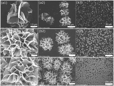
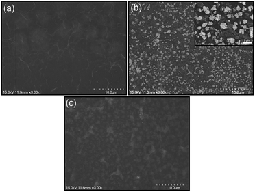
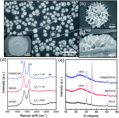
In this communication, we demonstrate a facile and efficient electrochemical strategy to fabricate flower-like GE-nanosheet clusters (f-GNSCs) in the presence of Cu particles. The resulting f-GNSCs exhibit improved supercapacitive performance due to the high accessible surface area and the enhanced ion movement and diffusion between the opened 3D interconnected GE-nanosheet petals. The overall synthetic procedure for f-GNSCs is illustrated in Scheme 1. First, a certain amount of graphene oxide (GO) ink was uniformly dropped on the surface of a conventional electrode followed by electrochemical reduction to GE; second, copper particles were electrodeposited on the surface of as-formed GE layer; and then another GO layer also followed by electrochemical reduction was coated on the copper particles to fabricate a sandwich construction of GE/Cu/GE on the surface of the electrode. This can be confirmed by the SEM images shown in Fig. 1. Finally, copper particles were removed under a positive potential, and simultaneously f-GNSCs formed (more detail, see ESI†). As the SEM images of f-GNSCs on glassy carbon (GC) electrode (f-GNSCs/GC) in Fig. 2a,b exhibited, GE-nanosheet clusters with flower-like structure and a diameter of 5–8 μm are uniformly dispersed on the surface of the underlaying GE layer on GC electrode. The inset in Fig. 2a shows that the resulting f-GNSCs are almost covered the whole scale of the GC electrode. The cross-section view of a f-GNSC on GC electrode is shown in Fig. 2c, demonstrating the 3D hierarchical structure of f-GNSCs composed of interconnected GE-sheet petals. Also, we observed that the bottom of the f-GNSC keeps close connection with the underlaying GE sheets, which ensures the good conductivity and stability of as-formed f-GNSCs. Besides the GC electrode, similar f-GNSCs can also be obtained on other conventional electrodes such as ITO glass (ITO-G), carbon fiber (CF), and gold electrode (Fig. S1–3†). The structure as well as the distribution of f-GNSCs are significantly dependent on the mass loading of the electrodeposited copper particles. As Fig. 3 exhibited, when few copper particles are deposited (0.024 mg cm−2), the resulting GE-sheet flower is wizened, small, and sparse. When the mass loading of copper increases to 0.048 as well as 0.096 mg cm−2, the obtained GE flower is growing to be blooming, vigorous, and dense, finally even connecting each other. Without additional statement, the f-GNSCs mentioned in the following were all obtained with the loading of 0.096 mg cm−2 Cu. In addition, the electrooxidation method of copper particles also determines the formation of f-GNSCs. A potentiostatic oxidation method rather than a potentiodynamical oxidation is favor to the formation of f-GNSCs.
 | ||
| Fig. 3 SEM images of f-GNSCs/GC electrodes in different magnification prepared with Cu mass loading of (a1–a3) 0.024, (b1–b3) 0.048 and (c1–c3) 0.096 mg cm−2, respectively. | ||
While, how do these f-GNSCs form? Apparently, the copper particles here are not identical to a hard template, since a hard template generally is a porous membrane that guides growth of the nanostructures within pores in the membranes, and this template is often removed after deposition or polymerization to obtain the pure nanostrucrures.23 However, in our experiments the formation of the f-GNSCs is closely related to the removal process of the copper particles. When a potential higher than the oxidation potential of Cu was added to the sandwich-structural GE/Cu/GE modified electrode (e.g. GE/Cu/GE/GC), an oxidation reaction (Cu → Cu2+ + 2e) occurred on the copper particles. As the reaction progressed, a great deal of Cu2+ ions produced, and these ions transported across the exterior GE layer and then diffused into the bulk solution (Scheme 1). With an increasing amount of Cu2+ ions continuously transporting across the exterior GE layer through the interspace between the GE nanosheets, the structure of the GE sheets coated on the copper particles would transform and turn to stand up from the surface of the substrate, due to the interactions between the moving Cu2+ ions and the exterior GE sheets. The rised GE sheets interconnected with each other, and as a result, the 3D f-GNSCs formed on the surface of the underlying GE layer. For the interactions, we consider that the GE sheets within GE/Cu/GE on the electrode are electronegative during the electrooxidation process, and there is an electrostatic attraction between the exterior GE sheets and the moving Cu2+ ions. Besides the electrostatic interaction, impact force as well as resistance may also exist as Cu2+ ions transported through the GE layer. It is these interactions that collectively caused the structural transformation of the GE sheets and then the formation of the flower-like architecture of GE. When the mass loading of Cu particles is larger, more Cu2+ ions are produced, and the interactions between the GE sheets and Cu2+ ions will be enhanced, resulting in the formation of blooming, vigorous, and dense GE flowers. This is consistent well with the SEM characterization of f-GNSCs dependent of the copper mass loading (Fig. 3 and S1–3†).
The microstructure of as-formed f-GNSCs on GC electrode was characterized by Raman spectroscopy. For comparison, pristine GO and GE layers on GC electrodes (GO/GC and GE/GC) were also characterized. As Fig. 2d shown, two characteristic peaks known as D-band (1350 cm−1) and G-band (1600 cm−1) are observed in the Raman spectra of f-GNSCs/GC, GE/GC and GO/GC electrodes. The D-band is attributed to the disordered turbostratic structures or defects in the curved GE nanosheets; the G-band is related to the phonons propagating along the graphitic structures.24,25 The intensity ratio of the D-band to the G-band, denoted by R = ID/IG, can be used to predict the amount of defects within the GE samples. When GO is reduced to GE, the intensity of D-band will increase, due to more defects introduced into the GE nanosheets. The R value of f-GNSCs/GC is 1.16, similar with that of GE/GC (1.18) but higher than that of GO/GC (0.82), indicating a good reduction degree of GE both for f-GNSCs/GC and GE/GCelectrodes, and that the formation of f-GNSCs does not destroy the intrinsic structural property of GE sheets. The 2D-band peaks located at about 2690 cm−1 demonstrate the multi-layer GE structrues of the samples. The f-GNSCs formed on ITO-G (f-GNSCs/ITO-G) were used for XRD characterization. Fig. 2e shows the XRD patterns of the bare ITO-G, GE/ITO-G, and f-GNSCs/ITO-G electrodes. Ignore the peaks originating from the ITO-G substrate, a broadened peak is observed at about 2θ = 24.7° arising from the (002) reflection of GE for both GE/ITO-G and f-GNSCs/ITO-G. The broadness of this peak is presumably due to the multilayer character of GE sheets and the structural defects induced by electrochemical reduction.26–28 The similar XRD patterns of f-GNSCs/ITO-G and GE/ITO-G demonstrate the GE-sheet composition of f-GNSCs.
Considering electrochemical methods and electrode substrates were used in our experiments, it is hard for us to obtain the specific surface area of f-GNSCs by characterizing their nitrogen adsorption–desorption isotherms. However, we calculated the electrochemical active surface area (ECSA) of f-GNSCs/GC on the basis of the charge associated with the oxidation and reduction of 5 mM K3Fe(CN)6 containing 1 M KCl (Fig. S4†), which can be also an important criterion to evaluate the electrochemical performance of porous materials. For comparison, the ECSA of the bare GC and GE/GC electrodes were also calculated based on the Randles–Sevcik equation, assuming mass transport only by the diffusion process,29,30
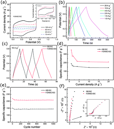
Due to its unique 3D flower-like architecture and high accessible surface area, the resulting f-GNSCs displayed excellent energy storage property. The performance of the supercapacitor f-GNSCs/GC electrode was evaluated by CV and galvanostatic charge/discharge tests in a three-electrode cell in comparison with that of GE/GC. As shown in Fig. 4a and Fig. S5a,† both the CVs of f-GNSCs/GC and GE/GC at different scan rates exhibit a quasi-rectangular shape, implying that an efficient electric double layer is established both in the two electrodes. Besides, a pair of redox peaks at about 0.30 and 0.36 V are observed in the CVs, corresponding to the redox reaction of residual oxygenic groups within GE sheets, which may provide pseudocapacitance.13,31,32 From these CVs, it can be found that the area surounded by the CV curves of f-GNSCs/GC is larger than that of GE/GC at the same scan rates, demonstrating the higher specific capacitance of f-GNSCs/GC. The galvanostatic charge-discharge behaviour at different current densities of both f-GNSCs/GC and GE/GC is exhibited in Fig. 4b and S5b.† All these charge-discharge curves show nearly symmetric shapes and linear slopes, revealing a good capacitive behaviour and electrochemical reversibility. The small deviation of the discharge curves from the ideal linear shape may be ascribed to the presence of pseudocapacitance. Moreover, the IR drops on all curves are similar and not obvious, even at a current density of 20 A g−1, indicating little overall resistance and excellent power characteristics of GE sheets. From Fig. 4c and Fig. S5c,† it is observed that the discharge time of f-GNSCs/GC is longer than that of GE/GC at the same current density, suggesting the superior capacitive performance of f-GNSCs/GC. According to the discharge curves at different current densities (Fig. 4b and S5b†), we calculate the specific capacitances of f-GNSCs/GC and GE/GC based on equation C = It/V, where I is the charge/discharge current density (A g−1), t is the discharge time (s), and V is the potential window (0.8 V). The current density and the reported specific capacitance here are all normalized to the weight of GE. Fig. 4d illustrates the current density dependence of specific capacitance of both the f-GNSCs/GC and GE/GC electrodes. It is clearly that the f-GNSCs/GC always demonstrates higher specific capacitance than GE/GC with the current density varying from 1.0 to 20 A g−1. For both the two electrodes, the capacitances take a rapid decrease at the beginning, and then slowly decrease as the current density increased. The capacitance of GE/GC is 188.7 F g−1 at 1.0 A g−1, while that of f-GNSCs/GC is as high as 347.1 F g−1. Capacitance of 207.9 F g−1 can still be maintained for f-GNSCs/GC even when the current density increases to 20 A g−1. The results presented here can be comparable to those of previously reported highly corrugated GE sheets (349 F g−1),27 hydrazine-reduced GE hydrogels (220 F g−1),14 GE/CNT composites (120–326.5 F g−1),32,33 and ultrathin planar GE (247 F g−1).16
The long-term cycling stability of f-GNSCs/GC and GE/GC were also examined using the galvanostatic charge-discharge technique at a current density of 10 A g−1 (Fig. 4e). For both the two electrodes, the capacitance decreases fast during the first 50 cycles, and then keeps almost constant with slight fluctuations up to 1000 cycles. For f-GNSCs/GC, about 95.0% of the initial capacitance is remained after 1000 times cycling comparable to that of GE/GC (96.1%) (Fig. S5d and e†). The capacitance decrease in the initial stage is possibly due to the irreversible redox reaction of the residual oxygenic groups in GE sheets. The above results highlight that the obtained f-GNSCs possess excellent electrochemical stability and a high degree of reversibility. Fig. 4f shows the impedance Nyquist plots of f-GNSCs/GC and GE/GC. As can be seen, the two electrodes show similar impedance spectra in form with a small quasi-semicircle at higher frequency region (inset) due to extremely small charge transfer resistance within GE sheets and a near–vertical curve at lower frequency region indicating the pure capacitive behavior. Moreover, the oblique line of f-GNSCs/GC is relatively vertical as compared with that of GE/GC, demonstrating that the f-GNSCs/GC behaves more closely as an ideal capacitor due to its 3D flower-like macroporous structure.
In addition, the influence of the mass loading of copper (the density of f-GNSCs) on the capacitive performance of f-GNSCs was also studied. The recorded CVs and charge-discharge curves of f-GNSCs/GC formed with different mass loading of copper (0.024, 0.048 and 0.096 mg cm−2) were shown in Fig. S6.† When the mass loading of copper is low (0.024 mg cm−2), the as-formed f-GNSC/GC shows little enhancement in capacitive performance as compared to that of GE/GC. With the increase in copper mass loading, the capacitive performance of f-GNSCs/GC keeps increasing due to their enhanced porous structure and high accessible surface area. Therefore, the larger mass loading of the copper, the higher surface area of as-formed f-GNSCs, and then, the better electrochemical performance of the f-GNSCs supercapacitor.
In summary, we have fabricated flower-like graphene-nanosheet clusters (f-GNSCs) on most conventional electrode substrates by electrochemical method. The preparation method is facile, feasible, cost-effective, and controllable. Due to their 3D macroporous structure and high accessible surface area, the as-formed f-GNSCs display outstanding capacitive performance, and are promising for high-performance energy storage devices. Besides, the f-GNSCs also show promising application prospect in electrochemical sensor and catalyst fields.
This work was supported by the National Natural Science Foundation of China (51073114, 20933007, 51373111, 51263010, 51272096), Suzhou Nano-project (ZXG2012022), and the Academic Award for Young Graduate Scholar of Soochow University.
Notes and references
- M. Pumera, Chem. Soc. Rev., 2010, 39, 4146 RSC.
- M. Pumera, Energy Environ. Sci., 2011, 4, 668 CAS.
- Y. Sun, Q. Wu and G. Shi, Energy Environ. Sci., 2011, 4, 1113 CAS.
- M. D. Stoller, S. Park, Y. Zhu, J. An and R. S. Ruoff, Nano Lett., 2008, 8, 3498 CrossRef CAS PubMed.
- Y. Zhu, S. Murali, W. Cai, X. Li, J. W. Suk, J. R. Potts and R. S. Ruoff, Adv. Mater., 2010, 22, 3906 CrossRef CAS PubMed.
- L. L. Zhang, R. Zhou and X. S. Zhao, J. Mater. Chem., 2010, 20, 5983 RSC.
- Y. Huang, J. Liang and Y. Chen, Small, 2012, 8, 1805 CrossRef CAS PubMed.
- M. F. El-Kady, V. Strong, S. Dubin and R. B. Kaner, Science, 2012, 335, 1326 CrossRef CAS PubMed.
- X. Li, X. Zang, Z. Li, X. Li, P. Li, P. Sun, X. Lee, R. Zhang, Z. Huang, K. Wang, D. Wu, F. Kang and H. Zhu, Adv. Funct. Mater., 2013, 23, 4862 CAS.
- Y. Meng, Y. Zhao, C. Hu, H. Cheng, Y. Hu, Z. Zhang, G. Shi and L. Qu, Adv. Mater., 2013, 25, 2326 CrossRef CAS PubMed.
- G. Ning, Z. Fan, G. Wang, J. Gao, W. Qian and F. Wei, Chem. Commun., 2011, 47, 5976 RSC.
- H. M. Jeong, J. W. Lee, W. H. Shin, Y. J. Choi, H. J. Shin, J. K. Kang and J. W. Choi, Nano Lett., 2011, 11, 2472 CrossRef CAS PubMed.
- Z. Lin, Y. Liu, Y. Yao, O. J. Hildreth, Z. Li, K. Moon and C. Wong, J. Phys. Chem. C, 2011, 115, 7120 CAS.
- L. Zhang and G. Shi, J. Phys. Chem. C, 2011, 115, 17206 CAS.
- Z. Wen, X. Wang, S. Mao, Z. Bo, H. Kim, S. Cui, G. Lu, X. Feng and J. Chen, Adv. Mater., 2012, 24, 5610 CrossRef CAS PubMed.
- J. J. Yoo, K. Balakrishnan, J. Huang, V. Meunier, B. G. Sumpter, A. Srivastava, M. Conway, A. L. Reddy, J. Yu, R. Vajtai and P. M. Ajayan, Nano Lett., 2011, 11, 1423 CrossRef CAS PubMed.
- B. You, L. Wang, L. Yao and J. Yang, Chem. Commun., 2013, 49, 5016 RSC.
- Z. Xu, Z. Li, C. M. B. Holt, X. Tan, H. Wang, B. S. Amirkhiz, T. Stephenson and D. Mitlin, J. Phys. Chem. Lett., 2012, 3, 2928 CrossRef CAS.
- X. Li, T. Zhao, Q. Chen, P. Li, K. Wang, M. Zhong, J. Wei, D. Wu, B. Wei and H. Zhu, Phys. Chem. Chem. Phys., 2013, 15, 17752 RSC.
- Q. Wang, J. Yan, Y. Wang, T. Wei, M. Zhang, X. Jing and Z. Fan, Carbon, 2013 DOI:10.1016/j.carbon.2013.09.070.
- Z. Bo, Z. Wen, H. Kim, G. Lu, K. Yu and J. Chen, Carbon, 2012, 50, 4379 CrossRef CAS PubMed.
- Y. He, W. Chen, X. Li, Z. Zhang, J. Fu, C. Zhao and E. Xie, ACS Nano, 2012, 7, 174 CrossRef PubMed.
- M. Wan, Conducting Polymers with Micro or Nanometer Structure, Tsinghua University Press, Beijing and Springer-Verlag GmbH, Berlin Heidelberg, 2008, p. 89 Search PubMed.
- Z. Zhou and X. Wu, J. Power Sources, 2013, 222, 410 CrossRef CAS PubMed.
- L. Malard, M. Pimenta, G. Dresselhaus and M. Dresselhaus, Phys. Rep., 2009, 473, 51 CrossRef CAS PubMed.
- Y. Bai, R. B. Rakhi, W. Chen and H. N. Alshareef, J. Power Sources, 2013, 233, 313 CrossRef CAS PubMed.
- J. Yan, J. Liu, Z. Fan, T. Wei and L. Zhang, Carbon, 2012, 50, 2179 CrossRef CAS PubMed.
- C. T. Hsieh, C. Y. Lin, Y. F. Chen, J. S. Lin and H. Teng, Carbon, 2013, 62, 109 CrossRef CAS PubMed.
- L. Wang and Y. Yamauchi, Chem. Mater., 2009, 21, 3562 CrossRef CAS.
- J. Lu, I. Do, L. T. Drzal, R. M. Worden and I. Lee, ACS Nano, 2008, 2, 1825 CrossRef CAS PubMed.
- Y. Bai, R. B. Rakhi, W. Chen and H. N. Alshareef, J. Power Sources, 2013, 233, 313 CrossRef CAS PubMed.
- S. Y. Yang, K. H. Chang, H. W. Tien, Y. F. Lee, S. M. Li, Y. S. Wang, J. Y. Wang, C. C. M. Ma and C. C. Hu, J. Mater. Chem., 2011, 21, 2374 RSC.
- D. Yu and L. Dai, J. Phys. Chem. Lett., 2010, 1, 467 CrossRef CAS.
Footnote |
| † Electronic supplementary information (ESI) available: Experimental; SEM images of f-GNSCs on different electrode substrates; Electrochemical characterization for f-GNSCs/GC and GE/GC electrodes. |
| This journal is © The Royal Society of Chemistry 2014 |


