Control of graphitization degree and defects of carbon blacks through ball-milling†
Su
Zhang
a,
Yuhua
Cui
a,
Bin
Wu
a,
Ranran
Song
a,
Huaihe
Song
*a,
Jisheng
Zhou
a,
Xiaohong
Chen
a,
Juzhe
Liu
a and
Lei
Cao
b
aState Key Laboratory of Chemical Resource Engineering, Beijing Key Laboratory of Electrochemical Process and Technology for Materials, Beijing University of Chemical Technology, Beijing, 100029, P. R. China. E-mail: songhh@mail.buct.edu.cn; Fax: +86-10-6443-4916; Tel: +86-10-6443-4916
bSiemens Ltd., China, Beijing, 100102, P. R. China
First published on 6th November 2013
Abstract
In most of the reports, ball-milling of graphitic materials would lead to the decrease of their crystal degree and further amorphization. However, large crystal enhancement of carbon black and graphitized carbon black induced by ball milling were herein observed. The hollow structure of the graphitized carbon black remained without collapse. But from high resolution transmission electron microscopy, the morphology of each nanoparticle is changed from polyhedron to sphere after a certain time of ball-milling. Accordingly, a transformation model was proposed.
1. Introduction
Ball-milling is an effective method for the synthesis of equilibrium and non-equilibrium materials.1 It is considered that the impact and shear stress applied during high energy ball-milling would cause the pulverization of large bulks along with the amorphization of their crystal structures. In previous work, ball milling was utilized to treat various carbon materials such as single- or multi-walled carbon nanotubes, cup-stacked carbon nanotubes, and graphite to synthesize new materials, change their morphologies or nanostructures, modify the surface textures, and enhance their storage performances. Li et al. obtained a tubular structure from the ball milling of graphite powder.2,3 By ball milling of graphite4 and carbon nanotubes,1 Chen et al. and Li et al. generated the closed-shell carbon nanoparticles and proposed the possible formation mechanisms. In recent years, wet ball-milling was applied to mechanically exfoliate graphite powder to prepare graphene nanosheets.5 Ball milling is also considered as a simple way to open the tips of carbon nanotubes and change their end morphologies.6–8 For the energy storage performances, ball-milled graphite powder was used as the electrode for electric double-layer capacitors9 and lithium ion batteries,10 and was found that both showed improved electrochemical performances. Besides, Ichikawa et al. also investigated the effect of ball milling on the hydrogen storage properties of graphite.11The intrinsic property variations such as crystal structure, morphology, defect, and electronic band structure should be clearly carried out firstly when investigated a modification effect on materials. For ball-milling carbon materials, various methods including X-ray diffraction (XRD), Raman spectroscopy, electron energy-loss spectroscopy (EELS), scanning electron microscopy (SEM), and high-resolution transmission electron microscopy (HRTEM) have been used to characterize the changes. In most of the previous reports, it is clearly indicated from the XRD patterns that the graphitic peak intensity of the carbon materials was significantly decreased with the elongated milling time.2,12–15 Besides, measured by Raman spectroscopy, the defect density was largely increased in graphite powder during ball-milling.16–18 Correlated to this result, Huang directly observed the introduced defects such as grain boundaries and curves by HRTEM.19 As a flat stacking structure connected by the weak van der Waals force between each layers, graphite is unstable and could be easily exfoliated across the planar direction under the mechanical shear and impact. Furthermore, with the introduction of defects and grain boundaries, the flat sheets became highly wrinkled or curved and the long range order of the crystals was broken down. Thus the graphite powder exhibited a reduced crystallinity when was treated by ball-milling. With a cylinder structure, carbon nanotubes show a more stable performance under mechanical milling compared with graphite. Pierard et al. reported that the graphitic peak intensity of carbon nanotubes in the XRD pattern increased after a certain time ball-milling.7,17 By further HRTEM observations, they attributed this enhancement to the self-assembly of polyaromatic carbon content. Briefly, carbon nanotube was progressively destroyed during ball milling and the small graphitic fragments from the collapse of the tubular structure were further assembled to an ordered stacking structure.
Although ball-milling is widely utilized, its effect on the structural transformation of carbon materials, especially nanosized carbon materials, was still unclear. Here, we demonstrated that ball-milling can enhance the crystal degree of nanostructured carbon blacks. For graphitized carbon black (GCB), the intensity of each diffraction peak in XRD patterns was largely enhanced even after a short time ball-milling, such as 0.1 h. For deep understanding, its precursor carbon black (CB) was milled, and the crystal degree enhancement including the increase of graphitic peak intensity along with the reduction of non-graphitic peak intensity was also clearly observed. The morphology change of GCB from polyhedron to concentric sphere of each GCB nanoparticle was further observed by SEM and HRTEM without collapse. We proposed a new mechanism from an energetic point of view and put forward a transformation model. It is attributed to bending of the graphitic faces and smoothing of the surface angles of GCB polyhedrons caused by mechanical impact, leading to the reduction of systematic energy. Our work could help to further understand the influence of ball-milling on carbon nanomaterials and advance new material design with mechanical chemistry.
2. Experimental
We used the CB (Mitsubishi Chemical Corporation, 24 nm) and GCB as the raw materials. GCB was obtained from the graphitization of CB at 2800 °C for 1 h in an argon atmosphere.Ball-milling apparatus (Nanjing NanDa Instrument Plant, QM-1SP2, Planetary Ball Mill) is composed of two agate mortars. 8 of big agate balls (ca. 0.6 g per ball) and 60 of small balls (ca. 0.3 g per ball), and 1 g of the raw material were added in one agate mortar. Ball-milling was taken at 425 rpm for 0.1, 1, 3, 9, and 24 h, respectively, and the obtained products were named as CB-time or GCB-time (e.g., GCB-0.1 stands for ball-milling of GCB for 0.1 h).
The crystal structure of the products were measured by XRD recorded on a Rigaku D/max-2500B2+/PCX system operating at 40 kV and 20 mA using CuKα radiation. Micro-Raman measurements were made with an Aramis system with 532 nm wavelength incident laser light. The morphology and structure were investigated by SEM (JEOL, FE-JSM-6701F) and HRTEM (JEOL-3010).
3. Results and discussion
Materials with high crystallinity can show intense and sharp diffraction peaks in their XRD patterns. From the XRD patterns of various ball-milled GCB given in Fig. 1a, the intensities of all diffraction peaks are largely increased with the decrease of full width at half maximum (FWHM), and the shape of the representative graphitic peaks is much the same from ball-milling 0.1 to 24 h, which indicates that the crystal degree of GCB is enhanced after ball-milling. This phenomenon is much different from the ball-milling of graphite powder and some of the carbon nanotube as we above mentioned.7,17 To the further understanding, the intensity to FWHM ratio of the (002) peak at ca. 26° of each sample was calculated and the results are shown in Fig. 1b. The crystal degree of GCB is obviously improved after 0.1 h ball-milling treatment, and remains at a certain high value. Besides, the peak positions of the (002) at 26°, (100) at 43.5°, and (222) at 54.8° remain unchanged. Since GCB is a multi-shell hollow structure, the unchanged peak position implies that the shells did not slip. Therefore, layer dislocation in GCB barely occurred during ball-milling.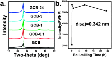 | ||
| Fig. 1 (a) XRD patterns of various ball milled GCB, (b) the ratio of intensity to FWHM of the [002] peaks at 26°. | ||
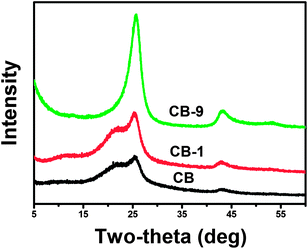
The initial high graphitization level makes the process of crystal degree enhancement difficult to be identified from the XRD patterns of various GCBs. For clear observation, low crystallinity of the precursor CB was chosen to mill for various time and the XRD patterns are shown in Fig. 2. A dispersive shoulder peak ranging from 15° to 23.7° in the XRD pattern of CB is attributed to the amorphous carbon (also called turbostratic carbon). With the elongation of the ball-milling time, the intensity of the graphitic carbon peak in the XRD pattern increases while the amorphous carbon peak reduces. Besides, the position of the amorphous carbon peak tends to a high-angle with the elongated treatment and merged into the graphitic peak after ball-milled for 9 h, indicating that the amorphous component in CB can transform to graphitic structure after a certain time ball-milling. This phenomenon further proven that ball-milling can enhance the crystal degree of carbon blacks.
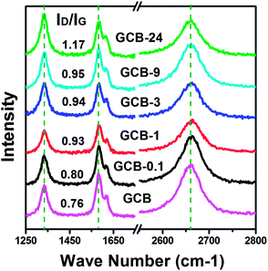
Raman spectroscopy is an effective way to investigate the defect density and electronic structure of carbon materials. Here, four typical Raman bands of ball-milled GCB are observed in Fig. 3. The unchanged frequency of the D-band at 1334 cm−1,20,21 G-band at 1582 cm−1,22 and 2D-band at 2661 cm−1 (ref. 22) during the ball-milling process indicates that the force constant of the C![[double bond, length as m-dash]](https://www.rsc.org/images/entities/char_e001.gif) C bonds and the electronic band structure of GCB are not changed. It is deduced that these closed-shell nanoparticles show much stable structure during ball-milling treatment, and barely exfoliation or collapse is occurred even milled for 24 h. The shoulder band which partially merged with the G-band at around 1618 cm−1 is the D′-band of GCB. It is a nonzero phonon density of states above the G-band whose appearance is due to the activation of certain defects in GCB.22,23 Furthermore, the increased ID/IG ratio (given in Fig. 3) illustrated that the defect density slightly increased with the elongated milling time.24
C bonds and the electronic band structure of GCB are not changed. It is deduced that these closed-shell nanoparticles show much stable structure during ball-milling treatment, and barely exfoliation or collapse is occurred even milled for 24 h. The shoulder band which partially merged with the G-band at around 1618 cm−1 is the D′-band of GCB. It is a nonzero phonon density of states above the G-band whose appearance is due to the activation of certain defects in GCB.22,23 Furthermore, the increased ID/IG ratio (given in Fig. 3) illustrated that the defect density slightly increased with the elongated milling time.24
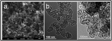
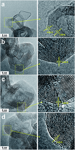
SEM and HRTEM were employed to investigate the microstructures of various ball-milled GCBs and the images are shown in Fig. 4 and 5 respectively. GCB exhibits a hollow polyhedral structure which the uniform particle size is ca. 25 nm. The particles are connected with each other and assembled like a string of beads (Fig. 4a and b). The polyhedral face contains several parallel stacking graphene layers, and these faces connected together to form a closed-shell cage with small curvature at the transition region of each two faces. From Fig. 5a, the interlayer spacings of the planar part (3.60 Å) and the transition region (4.02 Å) are much different. Besides, it is observed that hollow spherical structure tends to form from these polyhedral nanoparticles after ball-milling for 24 h (Fig. 4c).
The closed-shell graphitic structures of various ball-milled GCBs remain and barely collapse is observed even with the introduction of defects (Fig. 5), which is corresponding to the Raman spectroscopy, indicating that this system is much stable during mechanical impact. In this case, the crystal degree enhancement can't be explained by the self-assembly of small graphitic fragments from the breakdown of the closed-shell structures.17 However, it is noticed that the curvature of the transition regions is enlarged and the flat graphite sheets are curved during ball-milling. Therefore, the polyhedral structure of GCB tends to form as a spherical one. In the previous reports, flat graphite sheets can be bended and curl to turbostratic,25 highly curved,26 scroll,27 and closed-shell4 structures. From an energetic point of view, the spherical carbon “onions” are much stable than other forms of carbon nanoparticles.4,28 The high energy mechanical impact introduced by ball-milling could induce the transformation of the unstable polyhedral structure to a more stable one. Besides, the energy of the sharp transition regions between the polyhedral faces is much larger than that of the smooth regions; the curvature enlargement of these regions can effectively lower the energy of the system. Accordingly, the closed-shell polyhedron can transform to a sphere-like structure “spontaneously” by ball-milling and this transformation is driven by the energy minimization of the carbon system. We further measured the interlayer spacings of the graphene layers from the transition regions with different curvatures and the results are shown in the detail information of Fig. 5. The interlayer spacing is reduced with the increasing curvature. The phenomenon that the distance between the curved graphite layers of GCB-milled samples is similar to the planar graphite sheets is corresponding to the result of XRD tests.
We proposed a transformation model (Fig. 6) on the basis of above-mentioned information to explain how the ball-milling induced crystal degree enhancement in the closed-shell structure. Here, three concentric octagons with the same gap stand for the cross section of the primary CB or GCB (Fig. 6a). It shows much regular stacking structure at the region of parallel straight lines, but much disordered interlayer arrangement can be seen at the “sharp” edge site between each of two parallel domains. Therefore, in the polyhedral carbon blacks, large numbers of the “sharp” arrises are believed to cause the relative low crystal degree. With the elongated milling time, the flat graphite sheets are curved and the transition regions of the polyhedral faces are smoothed (Fig. 6b). After a certain time treatment, the regular octagons transformed to concentric circles, which stands for the change from polyhedron to a spherical structure (Fig. 6c). In this case, the “sharp” arris in polyhedron are efficiently eliminated by the formation of ordered homocentric spheres from strong mechanical impact, which leads to much uniform interlayer distance. As a result, the crystallinity of carbon blacks is largely enhanced. Moreover, dislocation between the graphitic shells was barely observed in the XRD patterns of these carbon blacks. Hence, we also pointed out the typical carbon atoms in the detail information of the model, which could clearly observe that even with the curvature change, the carbon atoms in each layers remained their relative position without slippage.
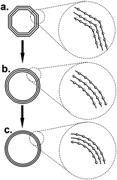 | ||
| Fig. 6 Transformation model of (a) polyhedron to (b) quasi-spherical and (c) concentric spherical structure in closed-shell carbon (nanostructures) nanoparticles. | ||
The intrinsic electrochemical performances of CB, CB-9, GCB, and GCB-24 as anode materials for lithium ion batteries were also measured. For both CB and GCB, the electrochemical impedances are increased while their specific capacities are reduced with the elongation of milling time. Details could be seen elsewhere in the ESI.†
4. Conclusions
The enhanced crystal degree of carbon blacks induced by ball-milling process was observed. For GCB, the crystal degree reached to a high value even after a short time treatment of 0.1 h and remained almost unchanged after milled for 24 h. For CB, the intensity of the amorphous carbon peak was reduced and the position shifted to a higher degree as well as the intensity of the graphitic peaks was increased with the elongated milling time. From the Raman spectroscopy and HRTEM measurement, this system kept a closed-shell structure without collapse. But the polyhedron of GCB nanoparticles transformed to a spherical one after a certain time of ball-milling. A possible mechanism model was proposed to explain the crystal degree enhancement and the structural transformation.Acknowledgements
This work was supported by the National Natural Science Foundation of China (51202009 and 51272019).Notes and references
- Y. B. Li, B. Q. Wei, J. Liang, Q. Yu and D. H. Wu, Carbon, 1999, 37, 493 CrossRef CAS.
- J. L. Li, L. J. Wang, G. Z. Bai and W. Jiang, Scr. Mater., 2006, 54, 93 CrossRef CAS PubMed.
- J. L. Li, Q. S. Peng, G. Z. Bai and W. Jiang, Carbon, 2005, 43, 2817 CrossRef PubMed.
- X. H. Chen, H. S. Yang, G. T. Wu, M. Wang, F. M. Deng, X. B. Zhang, J. C. Peng and W. Z. Li, J. Cryst. Growth, 2000, 218, 57 CrossRef CAS.
- W. F. Zhao, M. Fang, F. Wu, H. Wu, L. W. Wang and G. H. Chen, J. Mater. Chem., 2010, 20, 5817 RSC.
- Z. Kónya, J. Zhu, K. Niesz, D. Mehn and I. Kiricsi, Carbon, 2004, 42, 2001 CrossRef PubMed.
- N. Pierard, A. Fonseca, Z. Konya, I. Willems, G. V. Tendeloo and J. B. Nagy, Chem. Phys. Lett., 2001, 335, 1 CrossRef CAS.
- Á. Kukovecz, T. Kanyó, Z. Kónya and I. Kiricsi, Carbon, 2005, 43, 994 CrossRef PubMed.
- E. Gomibuchi, T. Ichikawa, K. Kimura, S. Isobe, K. Nabeta and H. Fujii, Carbon, 2006, 44, 983 CrossRef CAS PubMed.
- H. Wang, T. Ikeda, K. Fukuda and M. Yoshio, J. Power Sources, 1999, 83, 141 CrossRef CAS.
- T. Ichikawa, D. M. Chen, S. Isobe, E. Gomibuchi and H. Fujii, Mater. Sci. Eng., B, 2004, 108, 138 CrossRef PubMed.
- T. Fukunaga, K. Nagano, U. Mizutani, H. Wakayama and Y. Fukushima, J. Non-Cryst. Solids, 1998, 232–234, 416 CrossRef CAS.
- N. J. Welham and J. S. Williams, Carbon, 1998, 36, 1309 CrossRef CAS.
- M. Francke, H. Hermann, R. Wenzel, G. Seifert and K. Wetzig, Carbon, 2005, 43, 1204 CrossRef CAS PubMed.
- A. Smolira, M. Szymanska, E. Jartych, A. Calka and L. Michalak, J. Alloys Compd., 2005, 402, 256 CrossRef CAS PubMed.
- K. Niwase, T. Tanaka, Y. Kakimoto, K. N. Ishihara and P. H. Shingu, Mater. Trans., 1995, 36, 282 CAS.
- N. Pierard, A. Fonseca, J. F. Colomer, C. Bossuot, J. M. Benoit, G. V. Tendeloo, J. P. Pirard and J. B. Nagy, Carbon, 2004, 42, 1691 CrossRef CAS PubMed.
- Y. A. Kim, T. Hayashi, Y. Fukai, M. Endo, T. Yanagisawa and M. S. Dresselhaus, Chem. Phys. Lett., 2002, 355, 279 CrossRef CAS.
- J. Y. Huang, Acta Mater., 1999, 47, 1801 CrossRef CAS.
- S. D. M. Brown, A. Jorio, M. S. Dresselhaus and G. Dresselhaus, Phys. Rev. B: Condens. Matter Mater. Phys., 2001, 64, 073403 CrossRef.
- K. Sato, R. Saito, Y. Oyama, J. Jiang, L. G. Cancado, M. A. Pimenta, A. Jorio, G. G. Samsonidze, G. Dresselhaus and M. S. Dresselhaus, Chem. Phys. Lett., 2006, 427, 117 CrossRef CAS PubMed.
- Z. H. Ni, Y. Y. Wang, T. Yu and Z. X. Shen, Nano Res., 2008, 1, 273 CrossRef CAS PubMed.
- K. N. Kudin, B. Ozbas, H. C. Schniepp, R. K. Prud'homme, I. A. Aksay and R. Car, Nano Lett., 2008, 8, 36 CrossRef CAS PubMed.
- E. B. Barros, N. S. Demir, A. G. S. Filho, J. M. Filho, A. Jorio, G. Dresselhaus and M. S. Dresselhaus, Phys. Rev. B: Condens. Matter Mater. Phys., 2005, 71, 165422 CrossRef.
- Z. Q. Li, C. J. Lu, Z. P. Xia, Y. Zhou and Z. Luo, Carbon, 2007, 45, 1686 CrossRef CAS PubMed.
- J. Y. Huang, H. Yasuda and H. Mori, Chem. Phys. Lett., 1999, 303, 130 CrossRef CAS.
- J. L. Li, Q. S. Peng, G. Z. Bai and W. Jiang, Carbon, 2005, 43, 2817 CrossRef PubMed.
- D. Ugarte, Carbon, 1995, 33, 989 CrossRef CAS.
Footnote |
| † Electronic supplementary information (ESI) available. See DOI: 10.1039/c3ra44530e |
| This journal is © The Royal Society of Chemistry 2014 |

