In situ hydrogenation of molybdenum oxide nanowires for enhanced supercapacitors
Imran Shakir*ab,
Muhammad Shahidc,
Usman Ali Ranab and
Muhammad Farooq Warsid
aBK21 Physics Research Division, Department of Energy Science, Institute of Basic Science, SKKU Advanced Institute of Nanotechnology Sungkyunkwan University, 300 Cheoncheon-dong, Jangan-gu, Suwon 440-746, Republic of Korea. E-mail: shakir@skku.edu
bDeanship of scientific research, College of Engineering, King Saud University, PO-BOX 800, Riyadh, Saudi Arabia
cMaterial Science and Engineering, King Abdullah University of Science and Technology, Thuwal 23955-6900, Saudi Arabia
dChemistry Department, Baghdad-ul-Jaded Campus, The Islamia University of Bahawalpur, Bahawalpur-63100, Pakistan
First published on 3rd December 2013
Abstract
In situ hydrogenation of orthorhombic molybdenum trioxide (α-MoO3) nanowires has been achieved on a large scale by introducing alcohol during the hydrothermal synthesis for electrochemical energy storage supercapacitor devices. The hydrogenated molybdenum trioxide (HxMoO3) nanowires yield a specific capacitance of 168 F g−1 at 0.5 A g−1 and maintain 108 F g−1 at 10 A g−1, which is 36-fold higher than the capacitance obtained from pristine MoO3 nanowires at the same conditions. The electrochemical devices made with HxMoO3 nanowires exhibit excellent cycling stability by retaining 97% of their capacitance after 3000 cycles due to an enhanced electronic conductivity and increased density of hydroxyl groups on the surface of the MoO3 nanowires.
1. Introduction
Electrochemical energy storage devices, in particular supercapacitors based on layered transition metal oxides nanostructures, have attracted considerable interest due to their higher specific capacitance than conventional carbon based materials and better electrochemical stability than conducting polymers.1–4 Among various layered metal oxide nanostructures, molybdenum trioxide (MoO3) with a two-dimensional layered structure of linked MoO6 octahedra has gained considerable attention in supercapacitor applications as it can accommodate up to 1.5 Li/M.1 Furthermore, it offers a broad range of oxidation states which offer a broad range of redox reactions and van der Waals gaps between octahedron Mo–O sheets, used for the intercalation of foreign atoms which results in an enhanced pseudo capacitance.5–7 Despite the theoretical expectation that electrodes made from MoO3 exhibit low specific capacitance, poor cycling stability and rate capability due to their inherent poor electronic and ionic conductivity their performance in practical applications is limited.8 Many researchers have tried to improve the electronic conductivity of MoO3 based electrodes by exploring hybrid composite structures of MoO3 with polymers, MWCNTs or with graphite and its derivatives.5,6,9–11 Although MoO3 nanocomposites with MWCNTs exhibit a pronounced increase in specific capacitances, the incorporation of MWCNTs does not change the intrinsic properties of MoO3.6,9 Furthermore, the introduction of MWCNTs increases the fabrication cost and hence restricts the composite's potential development. Therefore, it is highly desirable to fundamentally improve the electrical conductivity, pseudocapacitance, and rate capability with a high specific capacitance while maintaining a low fabrication cost of MoO3. In order to address these issues, we have hypothesized that in situ hydrogenation of MoO3 nanowires during synthesis could address these limitations which consequently improve the specific capacitance and stability of MoO3 nanowires. We believed that the in situ hydrogenation of MoO3 results in the enhancement of the donor densities through the controlled introduction of oxygen vacancies which significantly lower the work function and increase the conductivity of MoO3 nanowires. Therefore it is expected that hydrogenation of MoO3 nanowires may be one of the best potential ways to solve the reaction kinetics and to increase the capacitance by increasing the ionic and electronic conductivity of MoO3 nanowires which leads to high capacity supercapacitors and is very promising for the next generation of high-performance electrochemical electrodes.2. Experimental methods
Molybdenum dioxide (MoO2) (99%), H2O2, HCl (38%), and ethanol were purchased from Sigma-Aldrich and used as received without further purification. MoO3 nanowires were synthesized by dissolving 10 mmol of MoO2 in 20 mL of H2O2 and stirred with a magnetic stirrer for 30 min and the pH of the solution was adjusted to 1–2 by the addition of dilute HCl with constant stirring.9 The resulting yellowish solution was transferred to a Teflon-lined stainless autoclave (25 mL capacity) at 180 °C for 10 h and then cooled to ambient temperature. The resultant white precipitates were filtered, washed several times with distilled water and ethanol, and dried on a hot plate at 120 °C for 12 h to completely eliminate the water and ethanol. For the synthesis of HxMoO3 (0 < x < 0.35) during the hydrothermal growth, a controlled amount of ethanol was introduced into the above yellowish solution and the solution was transferred to the Teflon-lined stainless autoclave (25 mL capacity) at 180 °C for 10 h and then cooled to ambient temperature. The color of the resulting HxMoO3 nanowires changed from white to blue and dark blue because of increasing hydrogen insertion which is attributed to the in situ hydrogenation of MoO3 nanowires.3. Material and electrode characterization
The morphological and structural properties were examined by field emission scanning electron microscopy (FE-SEM, JEOL JSM-7401F) and X-ray diffraction (XRD, D8 FOCUS 2200V, Bruker AXS, Cu Kα radiation (λ) 1.5418 Å). X-ray photoelectron spectroscopy (XPS; Perkin-Elmer PHI 660) was used to examine the effect of hydrogenation on the chemical composition and oxidation state of the MoO3 nanowires. All electrochemical measurements were carried out in a three-electrode assembly consisting of a Ag/AgCl, Pt foil and glassy carbon electrode (GCE) as a reference, counter and working electrode, respectively, using a Biologic VMP3 potentiostat/galvanostat. For the working electrode (glassy carbon), MoO3 and HxMoO3 nanowires were prepared by dispersing 10 mg of nanowires in 500 μL of ethanol by ultrasonication for 20 minutes. From this, 50 μL dispersion was placed on a glassy carbon electrode. The solvent was slowly evaporated by placing the electrode in an oven at 80 °C. A Nafion solution (5 μL) was coated on the electrode as a binder and allowed to dry at room temperature. Cyclic voltammetry was performed between 0 and 1 V vs. Ag/AgCl for various scan rates ranging from 5 to 100 mV s−1. Galvanostatic charge–discharge studies were performed by a Won A Tech Potentiostat/galvanostatic instrument (WPG, 100 South Korea).4. Results and discussion
The morphology of the MoO3 and HxMoO3 (0 < x < 0.35) nanowires was examined with field emission scanning electron microscopy (FE-SEM) and the results are presented in Fig 1. The FE-SEM images in Fig. 1(a and b) show that MoO3 and HxMoO3 nanowires have no difference in morphology, however, the diameter of the HxMoO3 nanowires was found to be lower than that of the pure MoO3 nanowires (∼100 nm for HxMoO3 whereas for pure MoO3 it is ∼150 nm) which clearly indicates the increased surface area of HxMoO3 nanowires providing more active sites for electrochemical reactions. Moreover, both MoO3 and HxMoO3 nanowires have an average length of 5 μm.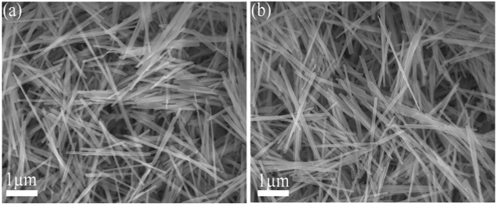 | ||
| Fig. 1 (a) FE-SEM image of the MoO3 nanowires synthesized at 180 °C for 10 hours, (b) FE-SEM image of the HxMoO3 nanowires synthesized at 180 °C for 10 hours. | ||
The crystallographic information of MoO3 and HxMoO3 was examined by X-ray diffraction and the XRD pattern is shown in Fig. 2a. The XRD patterns of the MoO3 and HxMoO3 nanowires are in good agreement with the standard peaks for the orthorhombic phase of MoO3 (JCPDS card 89-7112). The XRD results confirm that the in situ doping of hydrogen in MoO3 nanowires does not destroy the pristine crystal structure. However, in contrast to pure MoO3, the in situ hydrogen doping produced a slight shift (as shown in the inset of the main peak in Fig 2a) of the peaks towards a lower diffraction angle due to the expansion of the lattice unit cell of MoO3 which is in good agreement with previously reported results.12,13 The effect of in situ hydrogenation on the chemical composition and oxidation state of MoO3 nanowires was further analyzed using X-ray photoelectron spectroscopy (XPS). The high-resolution Mo 3d XPS core level XPS spectra of pristine and hydrogenated MoO3 nanowires are shown in Fig. 2b. The two broad peaks centered at ≈233 and ≈236 eV correspond well with the characteristic Mo 3d5/2 and Mo 3d3/2 peaks of Mo6+ in both MoO3 and HxMoO3 (0 < x < 0.35) nanowires as shown in Fig. 2(c and d).14–16 Compared with the XPS spectrum of Mo 3d of MoO3 nanowires, a small negative shift (∼0.2 eV) can be observed in the XPS spectrum of hydrogenated MoO3 nanowires as shown in Fig. 2d, demonstrating that the treatment with hydrogen caused a change of surface bonding of MoO3 nanowires. This decrease in binding energy of the Mo 3d electron is mainly due to the extra electron screening in the metallic cations and confirms that there are some Mo5+ ions in the HxMoO3 nanowires.17,18 We believed that the additional electrons in Mo5+ relative to Mo6+ are not strictly localized and HxMoO3 nanowires exhibit some metallic characteristics, probably due to these additional non-localized electrons which are essential to enhance the electrochemical performance of MoO3 nanowires without adding any conductive material like CNTs or carbon black. Furthermore, the deconvolution of O 1s peaks of MoO3 and HxMoO3 shows two contributions of oxygen O2− at a lower binding energy ≈531 eV (Mo–O–Mo) and surface adsorbed oxygen O− at a higher bonding energy ≈532 eV (Mo–OH). The Mo–OH peak intensity of the HxMoO3 nanowires is substantially higher than that of the pristine MoO3 nanowires, indicating that the MoO3 surface is functionalized by hydroxyl groups after hydrogenation which are suitable to enhance the pseudocapacitance in MoO3. To investigate the effect of hydrogenation on the electrical properties of MoO3, I–V curves were measured using a four probe station which includes a Keithley 2612 Source Meter. The electrical measurements reveal that MoO3 and HxMoO3 nanowires have electric resistances of 20.80 MΩ and 1.25 MΩ, respectively. This increase in conductance of HxMoO3 compared to MoO3 is mainly because hydrogenation increases the free electrons within the oxide's structure as inferred from the XPS data. To evaluate the electrochemical properties of MoO3 and HxMoO3 nanowires, electrochemical measurements were conducted in a three-electrode electrochemical cell with Pt wire and Ag/AgCl (satd KCl) electrodes as counter and reference electrodes in a 1 M H2SO4 electrolyte solution. The selection of this electrolyte is attributed to the fact that H+ in H2SO4 has a much smaller radius (0.012 Å) as compared to Na+ (0.95 Å) in NaOH and K+ (1.3 Å) in KOH which causes the faster transfer of electrolyte ions, and more and easier H+ insertion into the MoO3 and HxMoO3 nanowires. To investigate the effect of hydrogenation on the electrical properties of MoO3, electrochemical impedance measurements were conducted on the pristine MoO3 and HxMoO3 samples. Fig. 3a shows the Nyquist plots of the MoO3 and HxMoO3 nanowire electrodes. EIS indicated that the semicircle in the plot became shorter after the in situ hydrogenation of MoO3 nanowires proving the good electrical properties of the HxMoO3 that resulted from the hydrogenation.12,13,19 The electrical conductivity indicated that hydrogen played an important role in the conduction and had better electrochemical and electrical properties, which enable it to serve as an effective electrode material for energy storage devices. The EIS data were fitted by using an equivalent circuit showing the components of the whole impedance, bulk solution resistance (Rs), charge-transfer resistance (Rct), pseudocapacitive element (Cp) and a constant-phase element (CPE) accounting for the double-layer capacitance, as shown in the inset of Fig. 3a. In the high frequency area, the intersection of the curve at the real part Z0 indicates Rs of the electrochemical system, and the semicircle (which corresponds to Cp and Rct) displays the charge-transfer process at the working electrode–electrolyte interface. The Rct values were 100 and 345 Ω for MoO3 and HxMoO3 nanowires, respectively. As the redox reaction of MoO3 and HxMoO3 electrodes mainly occurs on the surface of the electrode, the capacity primarily depends on the interfacial charge-transfer resistance. The lower charge-transfer resistance of HxMoO3 nanowires as compared to MoO3 nanowires at the working electrode–electrolyte interface improves the electron transfer and the occurrence of the redox reaction leading to enhanced electrochemical properties.
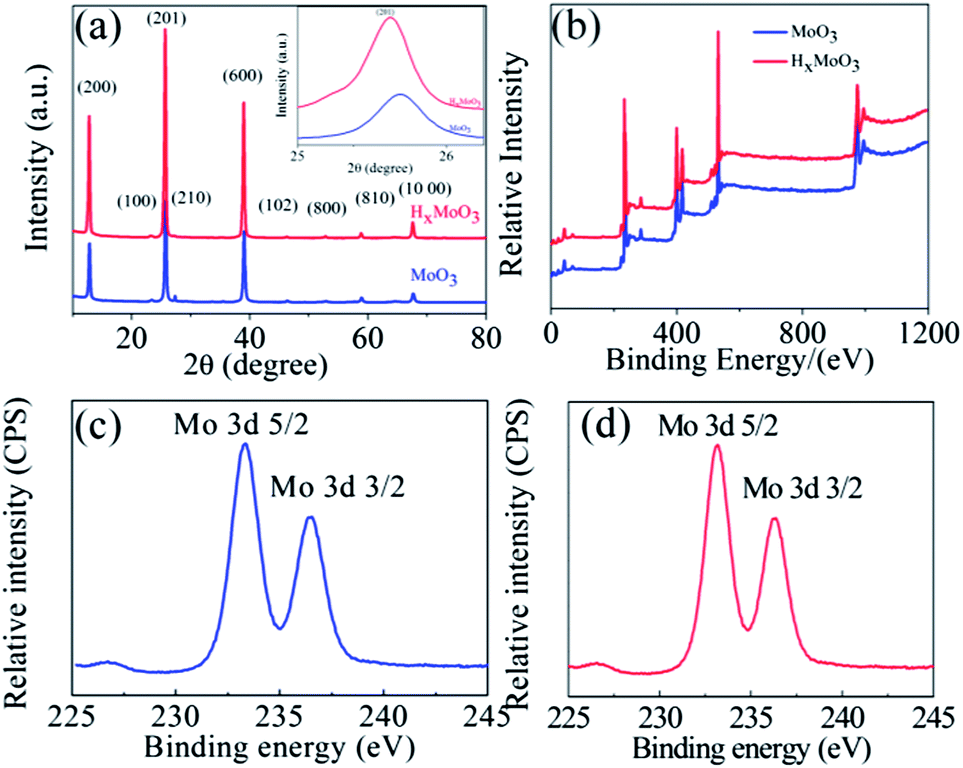 | ||
| Fig. 2 (a) XRD patterns of α-MoO3 and HxMoO3 nanowires synthesized at 180 °C for 10 hours (inset in (a) depicts the magnification of the (201) peak from the XRD spectrum), (b) XPS spectra of α-MoO3 and HxMoO3 nanowires, (c) XPS spectra of the Mo 3d electron in MoO3 nanowires and (d) XPS spectra of the Mo 3d electron in HxMoO3 nanowires. | ||
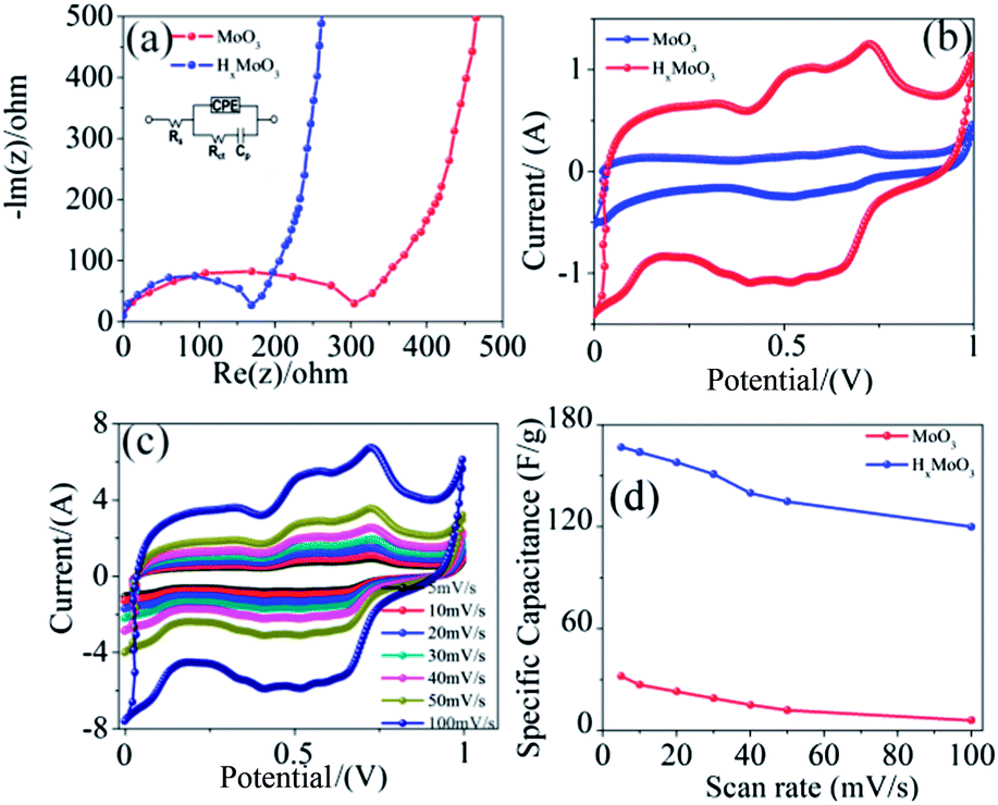 | ||
| Fig. 3 (a) Impedance analysis of the MoO3 and HxMoO3 nanowires in a 1 M aqueous solution of H2SO4 at room temperature. The inset shows the equivalent circuit diagram from the EIS analysis, (b) cyclic voltammograms (CVs) of the MoO3 and HxMoO3 nanowire electrodes at a scan rate of 20 mV s−1 in a 1 M aqueous solution of H2SO4, (c) CV of the HxMoO3 nanowire electrode at various scan rates from 5 to 100 mV s−1 in a 1 M aqueous solution of H2SO4 and (d) specific capacitance variation of the MoO3 and HxMoO3 nanowires with various thicknesses ranging from 5 nm to 20 nm electrodes at different scan rates. | ||
The electrochemical redox process in MoO3 and HxMoO3 nanowires was examined through cyclic voltammetry using 1.0 M H2SO4 as an electrolyte, in the voltage range of 0–1.0 V for various scan rates ranging from 5 to 100 mV s−1. Fig. 3b shows the cyclic voltammograms (CVs) of the MoO3 and HxMoO3 nanowire electrodes at a scan rate of 20 mV s−1. The HxMoO3 nanowire electrodes exhibited an elliptical curve and a much more enhanced capacitive current density as compared to the pristine MoO3 nanowires, indicating a faradaic reaction at the interface of the electrodes with the electrolyte ions, which is a typical behavior of pseudocapacitors. Fig. 3b shows three couples of redox peaks at 0.23 V–0.5 V (vs. Ag/AgCl), indicating three redox transformations at different oxidation states of Mo species including the MoIV, MoV and MoVI species.20–23 The rate performance of HxMoO3 nanowires was determined by studying the CV at different scanning rates as shown in Fig. 3c. The elliptical curve shapes of these CVs at different scan rates, increasing from 5 to 100 mV s−1, remain unchanged indicating a good capacitive behavior and high-rate capability of HxMoO3 nanowires. The variation of the specific capacitance with increasing scan rates for the nanowires is shown in Fig. 3b and it was observed that the specific capacitance of HxMoO3 is significantly higher than the pristine MoO3 nanowires. The HxMoO3 nanowire electrodes achieve specific capacitance of 120 F g−1 at a scan rate of 100 mV s−1, which is a 20-fold enhancement compared to the pristine MoO3 nanowires (6 F g−1) and also higher than the values recently reported for MoO3 nanowires and their composites.6,8
This enhancement in the electrochemical performance of HxMoO3 nanowires is mainly due to the increase in their electronic conductivity and density of the hydroxyl groups on the surface of the MoO3 nanowires, and thereby enhances the pseudocapacitance. It is imperative to note that the decrease in the specific capacitance of HxMoO3 nanowires at the higher scan rate of 100 mV s−1 is only 19%, indicating that hydrogenated nanowires have excellent capacitive characteristics and are a promising material for supercapacitor applications. In contrast, the pristine MoO3 nanowires retain only 39.8% of the initial capacitance, as the rate capability of the electrode material is related to the electrode conductivity and the rate of ion diffusion in the electrode. In the current study, MoO3 and HxMoO3 samples have the same nanowire morphologies, so they should have a similar ion diffusion rate. Therefore, the improved rate capacitance in the HxMoO3 nanowire sample (Fig. 3d) should be due to the enhanced electrical conductivity of the nanowire electrodes. The long-term electrochemical stability of HxMoO3 was examined by CV at a scan rate of 20 mV s−1 for 3000 cycles and the charge–discharge performance at a constant current of 0.5 A g−1, the corresponding results are presented in Fig. 4a and c respectively. The capacity decay was only 3%, even after 3000 cycles, indicating the excellent stability of the electrode material in energy storage applications. The electrochemical performance of MoO3 and HxMoO3 nanowires was further studied by galvanostatic charge–discharge measurements. Fig. 4b shows the charge–discharge curves of MoO3 and HxMoO3 nanowire electrodes collected at a current density of 0.5 A g−1. Both MoO3 and HxMoO3 nanowires showed a non-linear charge–discharge curve, indicating that the nanowires are pseudocapacitive with specific capacitances of 23 F g−1 and 168 F g−1 respectively. Additionally, a significant reduction in the IR drop can be observed in the charge–discharge curve of the HxMoO3 electrodes as compared to the MoO3 nanowires which further confirms the improvement of conductivity of nanowires by the in situ hydrogenation of MoO3. The influence of the current density on the specific capacitance of HxMoO3 nanowires is shown in Fig. 4d. The specific capacitance is high at low current densities, mainly due to the low ohmic drop, which enables the full access of the inner active sites or pores of the electrode. The decrease in capacitance values with an increasing current density is mainly because an effective utilization of the pseudocapacitive material for the ion insertion is limited to the outer surface of the electrodes.24,25 However, it is interesting to note that HxMoO3 nanowires, at higher current density of 10 A g−1, demonstrated a specific capacitance of 108 F g−1, a 36-fold higher value compared to 3 F g−1 for pristine MoO3 nanowires. This enhancement in the electrochemical performance of hydrogenated nanowires was mainly due to the increase in ionic conductivity of HxMoO3 compared to pristine MoO3 nanowires which allows easy diffusion of the mobile ions into the stacked layers of MoO3 that are held together by weak van der Waals forces.
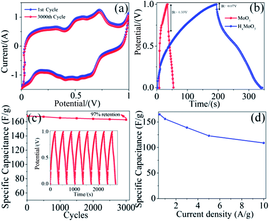 | ||
| Fig. 4 (a) Cyclic voltammetry of the first and after 3000 cycles of HxMoO3 nanowire electrodes with a scan rate of 20 mV s−1 in a 1 M aqueous solution of H2SO4, (b) galvanostatic charge–discharge curve of MoO3 and HxMoO3 nanowires at a charge–discharge current density of 0.5 A g−1, (c) cycling performance of HxMoO3 nanowire electrodes at a constant current of 0.5 A g−1 (the inset shows the charge–discharge curves of the last few cycles at a constant current of 0.5 A g−1), and (d) specific capacitance variation of HxMoO3 nanowires at different current densities. | ||
5. Conclusion
In conclusion, in situ hydrogenation of MoO3 nanowires was achieved through a simple, low cost hydrothermal method and this hydrogenation significantly improves the specific capacitance, rate capability and cycling stability of MoO3 nanowires as electrode materials for supercapacitors. The enhancement in electrochemical performance can be attributed to the combined contribution from the increased density of the surface hydroxyl group, and the improved ionic and electronic conductivity of MoO3 nanowires.Acknowledgements
The authors would like to extend their sincere appreciation to the Deanship of Scientific Research at the King Saudi University for its funding of this research through the Research Group Project no RGP-VPP-312.Notes and references
- T. Brezesinski, J. Wang, S. H. Tolbert and B. Dunn, Nat. Mater., 2010, 9, 146–151 CrossRef CAS PubMed.
- A. S. Aricò, P. Bruce, B. Scrosati, J. M. Tarascon and W. Van Schalkwijk, Nat. Mater., 2005, 4, 366–377 CrossRef PubMed.
- L. Dai, D. W. Chang, J. B. Baek and W. Lu, Small, 2012, 8, 1130–1166 CrossRef CAS PubMed.
- Y. G. Guo, J. S. Hu and L. J. Wan, Adv. Mater., 2008, 20, 2878–2887 CrossRef CAS.
- L. S. Aravinda, K. K. Nagaraja, K. U. Bhat and B. R. Bhat, J. Electroanal. Chem., 2013, 699, 28–32 CrossRef CAS PubMed.
- Q. Mahmood, H. J. Yun, W. S. Kim and H. S. Park, J. Power Sources, 2013, 235, 187–192 CrossRef CAS PubMed.
- W. Tang, L. Liu, S. Tian, L. Li, Y. Yue, Y. Wu and K. Zhu, Chem. Commun., 2011, 47, 10058–10060 RSC.
- I. Shakir, M. Shahid, H. W. Yang and D. J. Kang, Electrochim. Acta, 2010, 56, 376–380 CrossRef CAS PubMed.
- I. Shakir, M. Shahid, S. Cherevko, C. H. Chung and D. J. Kang, Electrochim. Acta, 2011, 58, 76–80 CrossRef CAS PubMed.
- J. Li, X. Y. Wang, Q. H. Huang and C. L. Dai, Chin. J. of Nonferrous Met., 2006, 16, 1468–1473 CAS.
- W. Sugimoto, T. Ohnuma, Y. Murakami and Y. Takasu, Electrochem. Solid-State Lett., 2001, 4, A145–A147 CrossRef CAS PubMed.
- L. Shen, E. Uchaker, X. Zhang and G. Cao, Adv. Mater., 2012, 24, 6502–6506 CrossRef CAS PubMed.
- X. Lu, G. Wang, T. Zhai, M. Yu, J. Gan, Y. Tong and Y. Li, Nano Lett., 2012, 12, 1690–1696 CrossRef CAS PubMed.
- X. K. Hu, Y. T. Qian, Z. T. Song, J. R. Huang, R. Cao and J. Q. Xiao, Chem. Mater., 2008, 20, 1527–1533 CrossRef CAS.
- I. Shakir, M. Shahid and D. J. Kang, Chem. Commun., 2010, 46, 4324–4326 RSC.
- X. Hu, D. Ma, L. Xu, Y. Zhu and Y. Qian, Chem. Lett., 2006, 35, 962–963 CrossRef CAS.
- R. J. Colton, A. M. Guzman and J. W. Rabalais, J. Appl. Phys., 1978, 49, 409–416 CrossRef CAS PubMed.
- T. H. Fleisch and G. J. Mains, J. Chem. Phys., 1982, 76, 780–786 CrossRef CAS PubMed.
- P. Yang, X. Xiao, Y. Li, Y. Ding, P. Qiang, X. Tan, W. Mai, Z. Lin, W. Wu, T. Li, H. Jin, P. Liu, J. Zhou, C. P. Wong and Z. L. Wang, ACS Nano, 2013, 7, 2617–2626 CrossRef CAS PubMed.
- L. Ma, X. Zhao, F. Si, C. Liu, J. Liao, L. Liang and W. Xing, Electrochim. Acta, 2010, 55, 9105–9112 CrossRef CAS PubMed.
- E. I. Santiago, G. A. Camara and E. A. Ticianelli, Electrochim. Acta, 2003, 48, 3527–3534 CrossRef CAS.
- N. P. Lebedeva and G. J. M. Janssen, Electrochim. Acta, 2005, 51, 29–40 CrossRef CAS PubMed.
- Z. Cui, W. Yuan and C. M. Li, J. Mater. Chem. A, 2013, 1, 12926–12931 CAS.
- M. Shahid, J. Liu, Z. Ali, I. Shakir and M. F. Warsi, J. Power Sources, 2013, 230, 277–281 CrossRef CAS PubMed.
- L. Peng, X. Peng, B. Liu, C. Wu, Y. Xie and G. Yu, Nano Lett., 2013, 13, 2151–2157 CrossRef CAS PubMed.
| This journal is © The Royal Society of Chemistry 2014 |