Dielectric core–shells with enhanced scattering efficiency as back-reflectors in dye sensitized solar cells

Nahid Ghazyania, Mohammad Hossein Majles Araa, Fariba Tajabadi*c, Ali Dabirian*b, Raheleh Mohammadpourc and Nima Taghavinia*bc
aPhotonics Laboratory, Physics Department, Kharazmi University, Tehran 15614, Iran
bNanoparticles and Coating Laboratory, Department of Physics, Sharif University of Technology, Tehran 14588, Iran. E-mail: dabirian@sharif.edu; taghavinia@sharif.edu; Fax: +98 21 66022711; Tel: +98 21 66164570
cInstitute for Nanoscience and Nanotechnology, Sharif University of Technology, Tehran 14588, Iran. E-mail: tajabadi@ncl.sharif.edu; taghavinia@sharif.edu; Fax: +98 21 66164119; Tel: +98 21 66164570

Received 1st August 2013 , Accepted 2nd October 2013

First published on 4th October 2013


Abstract

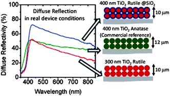
Particulate back-reflector films are conventionally used for the improvement of light harvesting in dye solar cells (DSC). The back-reflection of the films is directly related to the scattering efficiency of the individual particles. Inspired by the idea of multilayer optical thin films, here it is demonstrated theoretically and experimentally that putting a SiO2 shell around spherical rutile-TiO2 particles leads to improved light scattering by the particles. These dielectric core–shells not only enhance the overall diffuse reflection of the films, but they also cause a relative improvement in the red and near infrared regions. Back-reflector films of these core–shell particles employed in DSCs result in an enhanced device efficiency of up to 9.52%. Contrary to the general notion, the conventional DSC back-reflector films are far from ideal, i.e. they show less than a 50% reflection in real device conditions. This is due to the limited thickness of the films (a few micron), as well as the low “wet” reflection of the back-reflector films, i.e. the reflection of the scattering particles embedded in a liquid electrolyte. This fact reveals the need for more optimized scattering particles. We suggest dielectric core–shell particles as an alternative.

Introduction

Dye sensitized solar cells (DSC) present an attractive technology because their production cost is low and in contrast to silicon solar cells the fabrication does not require an extensive semiconductor industry infrastructure.1–3 These solar cells consist of charge transfer dye molecules sandwiched between a mesoporous oxide n-type semiconductor, usually TiO2, and a regenerative redox electrolyte.4,5 The common dye molecules used in DSCs to sensitize the mesoporous TiO2 structure, have small absorption coefficients particularly in the red and the near-infrared (NIR) parts of the sunlight spectrum, therefore proper optical design is essential to achieve considerable light harvesting in these spectral regions.6–8 This issue cannot be improved much by simply increasing the film thickness due to the limited electron diffusion length.9–11

Traditionally, a back-reflector film consisting of wavelength-scale TiO2 particles (∼400 nm anatase particles) placed between the dye sensitized layer and the electrolyte has been employed to scatter the incident light back into the dye sensitized layer and therefore increase the optical path length within the cell.8,12,13 These back-reflectors considerably improve the light harvesting efficiency of cells.12 In principle, individual submicron TiO2 particles scatter the electromagnetic wave (light), through Mie scattering. The light scattered off a scattering layer made of these particles back into the cell acquires a tapered Lambertian diffuse reflectivity profile.14 A collection of other TiO2 morphologies has also been suggested so far, with the single function of light scattering, or dual functions of light scattering plus dye adsorption. These include mesoporous TiO2 beads,15 hierarchical TiO2 spheres,16–18 hexagonal TiO2 microplates,19 mesoporous TiO2 aggregates,20 mesoporous fibers21,22 and TiO2 hollow spheres.23 Non-TiO2 materials such as ZrO224 and SnO225 have also been tried as back-reflector materials. Several other approaches have also been pursued to prolong the optical path length in the dye sensitized layer of DSCs including surface plasmon effects, photonic crystals, gratings, and scattering elements. Among these approaches, enhanced near-fields and scattered fields of noble metal nanostructures due to the excitation of surface plasmons has attracted significant attention. However despite the great potential of these structures, the reported enhancements for DSCs are not yet significant. Photonic crystals and gratings have also attracted attention recently, though they usually require complex fabrication procedures; something that is not desirable in DSCs. Embedded dielectric scatterers appear to be an attractive option, but these structures basically modify the dye sensitized layer, which requires the further optimization of this layer.7 Despite this whole diversity of methods, so far the highest light harvesting efficiencies are obtained using the conventional bilayer structure, consisting of submicron particles, on top of the dye sensitized TiO2 mesoporous film.6

Even with a back-reflector film, the external quantum efficiency for λ = 700 nm ± 100 nm region (λ: wavelength) is still low, even for the best reported cells. For a typical N719 sensitized mesoporous TiO2 film, the penetration depth of light at 700 nm is about 38 μm (Fig. S1. ESI). This value should be compared with the thickness of the mesoporous film: typically 10 μm in liquid DSCs and about 2 μm for solid state DSCs. This demonstrates the need for further improvement of light harvesting in the red part of the spectrum. Part of the reason for the insignificant improvement in red-NIR is the relatively low diffuse reflectance of the back-reflector films in this region. While the reflectance of the conventional particulate back-reflectors (consisting of submicron anatase TiO2 particles) is often thought to be nearly ideal, here we show that these scatterers have a lot of room for improvement. As will be seen in this paper, for a commercial anatase back-reflector film of 8 μm thickness, the total reflectivity is about 45% for λ = 700 nm. For a 6 μm film of rutile particles this value is about 30%. This means that the scattering efficiency of individual particles is not sufficient to reflect the whole light back, that is, part of the light is lost by transmission. Certainly, this can be improved by increasing the thickness of the back-reflector film. However, the thickness is technically limited by, for instance, the processing cost, cracking in thick films, anode–cathode spacing, and so on.

In practice, where these back-reflector films are used inside the cell, the submicron TiO2 particles are surrounded by an electrolyte with a refractive index of ∼1.4. In this case the reflectance deteriorates by about 20% to 30% because the scattering elements are surrounded by the electrolyte which has a refractive index larger than air. Measurements of reflectivity values in the presence of an electrolyte is generally ignored in the literature. The effect of electrolyte, plus the limited film thickness, results in real reflectivity values of less than 50% for conventional back-reflector films. This highlights the fact that DSC back-reflectors are far from ideal and still have room for improvement. They can be improved by using particles with higher scattering efficiencies that show enhanced reflectivities in real conditions.

In this work, we demonstrate how dielectric core–shell structures can result in a considerable improvement in the scattering efficiency of individual particles. We further show how these core–shell particles can help improve the light harvesting efficiency of DSCs. So far the modification of the scattering properties of particles, through growing shells on the particles, has not been studied. The common rule to obtain a large scattering efficiency is to use materials with a high refractive index (such as rutile or anatase TiO2) and particle sizes of the same order as the wavelength. Calculations on TiO2 particles have shown that the optimum size is in the range 300–400 nm.27 However, the reflectivity of the back-reflector films by these particles generally shows decreased values for longer wavelengths, e.g. in the red-NIR region. This is because the scattering efficiency is reduced at longer wavelengths and therefore part of the light is transmitted through the film. It is shown in this paper how adding a shell of SiO2 on rutile particles (rutile@SiO2) may improve the scattering in the entire visible and NIR wavelength range. The physical properties of rutile TiO2, including its large index of refraction (2.8),28 have made it the world's most widely used white pigment for different applications.29 Rutile films with a thickness of a few micrometers have a nearly ideal reflectance spectrum at wavelengths shorter than 500 nm, however their reflectance rapidly decays at red and NIR wavelengths. This effect is highly undesirable in DSCs. Here we demonstrate that rutile@SiO2 scatterers largely prevent reflectance decay in red and NIR wavelengths. These scatterers show a superior performance compared to both rutile and commercial anatase (JGC) scatterers over the entire wavelength range. DSCs fabricated using these scatterers show photovoltaic efficiencies close to 10%.

Theoretical modelling

Light interaction with the scattering layer is a classic problem of light transport in a disordered dielectric. When the light penetration depth in the scattering layer, l*, is larger than the wavelength, the light transport is described as a diffusion process with a transport mean free path l*.30 In a lossless scattering layer the reflectance off the layer is proportional to the dimensionless parameter λ/l*. The l* is proportional to the inverse of the back scattering cross section of individual scatterers, therefore improving the back scattering cross section of individual scatterers in the layer results in smaller l* values; hence improving the reflectance from the scattering layers.

Fig. 1a shows spectra of the calculated normalized back-scattering cross sections of 300 nm rutile nanoparticles before and after coating with a 50 nm thick silica layer. These values are calculated from the electromagnetic fields calculated using three-dimensional finite elements simulation of individual spherical scatterers under z-polarized light incidence described by Ē = ẑe-jkx where k is the wave number. The back-scattering cross section, σsca, is calculated by the relation:

 
σsca = |Ēinc|−2half space|Ēsca|2dΩ (1)
where |Ēinc| is the amplitude of the incident field, |Ēsca| is the amplitude of the scattered field, and dΩ describes the unit of the solid angle.31 The peaks observed in the graph are due to resonances within the nanoparticles because scattering is strong at resonances similar to resonances in atomic systems.32 The broad peak observed in the rutile spectrum in the NIR maintains its shape and amplitude however it red shifts after silica coating. The spectrum of rutile shows two relatively narrow peaks near 500 nm and 600 nm, which are transformed into a broad peak covering up to 650 nm after 50 nm silica coating. Essentially the rutile peaks broaden and merge into a broadband feature upon silica coating.


image file: c3ra44079f-f1.tif
Fig. 1 (a) Back-scattering cross section normalized to the square of the wavelength calculated for 300 nm silica, anatase, and rutile nanoparticles with and without 50 nm silica coating. The particles are illuminated with a z-polarized plane wave travelling along the x-axis of Cartesian coordinates. (b) Color plots of electric field amplitudes within 300 nm rutile nanoparticles coated with 50 nm silica at wavelengths corresponding to the peaks in the back-scattering cross section spectrum. The incident plane wave comes from the left side.

The peak broadening is attributed to the introduction of an index matched silica layer that provides a channel for the confined Mie resonance within the rutile nanoparticles to leak its energy to free-space.33,34 Basically in rutile and rutile@SiO2 nanoparticles the quality factor of resonances are determined by radiation losses from the cavity. The radiation loss of the resonance mode decreases with the refractive index contrast and therefore the silica layer effectively reduces the refractive index contrast hence reducing the quality factor of Mie resonances. The quality factor is proportional to ω0ω, where ω0 is the resonance frequency and Δω is the width of resonance.33,34 Profiles of electric field amplitude inside silica coated rutile nanoparticles at three different wavelengths corresponding to the peak of the features are observed in Fig. 1a. The electric field profile shows the typical shape of second and third order Mie resonances within rutile nanoparticles, however their field profile shows a clear overlap with silica and the surroundings facilitating the out coupling of the resonance energy.

In practical situations, rutile sub-micron particles are produced with a certain size distribution. Therefore to estimate the back scattered light from a scattering layer formed by these nanoparticles we need to consider the effect of size distribution. Fig. S2 (ESI) shows the back-scattering cross section of 300 nm, 340 nm, 400 nm rutile particles coated with a 50 nm thick silica layer. The broad peak which appeared as the result of silica coating shifts to a longer wavelength and it also becomes broader as the rutile nanoparticle becomes larger. This broad peak covers up to 850 nm as the size of the rutile becomes 400 nm. Therefore we expect that the reflectance of a scattering layer formed from 300–400 nm rutile particles with a 50 nm silica layer is enhanced compared to the reflectance from the rutile scattering layer. The back scattering cross section values calculated for the silica thickness of 70 nm on 300 nm rutile particles (Fig. S3) shows small variations in the position and amplitudes of the peaks in the spectrum, however the spectrum essentially remains similar. Therefore the performance of the scattering layer made from these core–shell particles is robust against variations in the shell thickness.

Experimental results

The core–shell particles were synthesized and applied as back-reflector films in DSCs. Rutile particles were coated by a SiO2 shell by adding 3.5 ml ammonia (25%, Merck) and 2.8 ml tetraethylorthosilicate (TEOS, Merck) into a 40 ml ethanolic sol of 2.5 wt% rutile particles, and stirring for 75 min at ambient temperature. The obtained rutile@SiO2 particles were extracted and re-dispersed in absolute ethanol. Fig. 2a and b show the scanning electron microscopy (SEM, Mira Tescan) images of the rutile and the rutile@SiO2 particles. The rutile particles have irregular shapes with a mean diameter of about 300 nm which is the optimum size for strong scattering in the visible light region. The size of the rutile@SiO2 particles is, on average, larger, due to the additional shell thickness. Dynamic light scattering (DLS, Malvern) of well dispersed particles in ethanol shows that the rutile@SiO2 particles are about 140 nm larger than the rutile particles, that is, a 70 nm SiO2 shell is formed on the particles (Fig. 2c).
image file: c3ra44079f-f2.tif
Fig. 2 SEM images of screen printed layers of rutile particles (a) and rutile@SiO2 particles (b). The scale bar is 1 μm. The very small particles in the images are 20 nm TiO2 particles used as the binder. The SiO2 shelled rutile particles are larger than unshelled particles. The size distribution of particles was measured using DLS (c). The average shell thickness is estimated to be 70 nm.

Back-reflector films of the rutile and the rutile@SiO2 particles were deposited by screen printing their pastes for 1 or 2 times (designated as 1L and 2L). The composition of the pastes were 15 wt% TiO2 particles, 80 wt% terpineol (Merck), 3 wt% ethylcelloluse (Fluka) and 2 wt% of 10 nm TiO2 particles as a binder (obtained following the peptization step). A commercial paste of anatase TiO2 particles (JGC-PST-400C) was also utilized as a reference (here denoted as an anatase film). Fig. 3a illustrates the diffuse reflectivity of the 1L and 2L pasted films in air (Avaspec 2048TEC). The thickness of the 1L and 2L films are 6 μm and 10 μm, for the rutile and the rutile@SiO2 films and 8 μm and 12 μm for the anatase film. The absorption edge around 400 nm corresponds to the bandgap of the anatase and the rutile TiO2, which are slightly different (Eg (rutile) = 3.0 eV, Eg (anatase) = 3.2 eV). It is apparent that in this range of film thickness, which is usual in DSCs, the reflectivity values are far from ideal. A remarkable increase in the reflectivity is observed for the 2L films compared to the 1L films, while even for the 2L films the red-NIR reflectivity is below 75%. This is an important fact that justifies the serious need for the optimization of the back-reflector films in DSCs. The non-reflected light is transmitted through the film and lost.


image file: c3ra44079f-f3.tif
Fig. 3 DRS graphs of anatase (JGC), rutile and rutile@SiO2 particulate films. (a) Comparison of the diffuse reflectivity of 1 layer (1L) and 2 layer (2L) printed films. The thickness of the 1L and 2L films are 6 μm and 10 μm for the rutile and the rutile@SiO2 films, and 8 μm and 12 μm for the anatase film. The reflectivities increase with thickness, indicating that there is some transmission loss in this thickness range. (b) Diffuse reflectivity of the 2L films filled with the electrolyte (MPN), compared to measurements in air. One clearly notes the remarkable change in the reflectivity by filling with the electrolyte.

The rutile@SiO2 films show clearly a higher reflectivity compared to both the rutile and the anatase films, though the anatase reference films are slightly thicker than the rutile and the rutile@SiO2 films. This can be attributed to the larger scattering cross section of the rutile@SiO2 particles, as indicated in our calculations. This enhancement is observed in the whole visible and NIR regions. For the rutile films, the reflectivity curves have a high downward slope; that is, their reflection at a longer wavelength declines remarkably. This is due to the smaller scattering cross section of these particles at long red and NIR wavelengths. This decreasing trend is considerably improved for the rutile@SiO2 films. The reason can be again attributed to the enhanced scattering cross section caused by the SiO2 shell. For the commercial anatase films the reflectivity is almost flat in the whole wavelength region, which is possibly due to its large distribution of particle size (Fig. S6. ESI).

In real conditions, the scattering particles of the back-reflector films are surrounded by the DSC electrolyte with a refractive index of about 1.4.26 This may significantly alter the reflectivity values. Fig. 3b displays the results for the diffuse reflectivity measurements when the pores of the films were filled by 3-methoxypropionitrile (MPN). The refractive index of MPN is 1.4, which is close to the real electrolyte. The figure compares the diffuse reflection of the 2L films for wet (MPN) and dry (air) films. The trend for the 1L films is similar. There is a considerable reduction in reflectivity in a liquid compared to air. For the anatase and rutile films the reflectivity falls below 50%. However, for the rutile@SiO2 film the decreased reflectivity is still larger than the others. This demonstrates that the rutile@SiO2 core–shell particles exhibit a higher scattering efficiency compared to unshelled particles.

The particulate films of the rutile, the rutile@SiO2 and the commercial anatase were used as back-reflector films in DSCs. A transparent mesoporous film of 20 nm TiO2 particles (Sharif Solar) was used as the dye sensitized layer. The details of the cell fabrication process are presented in the ESI. Fig. 4 displays the device performance of the cells without a back-reflector film (T), and with rutile (T/Rutile), anatase (T/Anatase) and rutile@SiO2 (T/Rutile@SiO2) back-reflectors. In Fig. 4a the current–voltage data under AM1.5 G illumination (Luzchem Solar Simulator) are presented. The intensity was calibrated with a certified silicon solar cell and a black mask with a slightly higher area than the active area of the solar cells was used for the measurements. One notes that the open circuit voltage (Voc) is almost identical for all the cells. The fill factors are also equal, within 1%. The main difference in the conversion efficiency (η) stems from the different current density, which is presumably a result of light harvesting efficiency. The efficiency results are reproducible within 3%. As demonstrated in Fig. S5, the electrical characteristics of the cells having different back-reflector films are essentially the same. The fact that the electron lifetime and electron transport time are almost identical provides evidence that the difference in the conversion efficiency is not caused by the different electron collection efficiency.


image file: c3ra44079f-f4.tif
Fig. 4 Device performance of DSCs with a photoanode consisting of a transparent TiO2 film of 6 mm, without a scatterer film (T) and with scatterer films of anatase (JGC), rutile and rutile@SiO2 particles. (a) JV plots and table of parameters for the cells. While the open circuit voltage and fill factor are almost identical, the effect of the scatterers is clearly different for a short circuit current. The cell with the rutile@SiO2 scatterer shows the highest current density. (b) The incident photon conversion efficiency (IPCE) for the cells. The light harvesting efficiency is larger for the cell with the rutile@SiO2 film.

The current density, Jsc, of the cell without a back-reflector film (T) is 14.7 mA cm−2. The value of Jsc is increased to 17.4 mA cm−2, 16.2 mA cm−2 and 19.6 mA cm−2 for the anatase, rutile and rutile@SiO2 cells, respectively. It is evidently clear that the rutile@SiO2 back-reflectors provide a better light harvesting efficiency. This certainly stems from the higher scattering cross section of the individual particles. Fig. 4b illustrates the incident photon to current conversion efficiency (IPCE), measured using a setup consisting of a Jarrel-Ash monochromator, a 100 W halogen lamp and a calibrated photodiode (Thorlabs). The value of the IPCE in the whole wavelength range is increased by utilizing a back-reflector film. This is expected for the cells with a mesoporous TiO2 thickness of 6 μm, which is not very thick to completely absorb the green part of the light, whereas the C101 dye absorbs more strongly. The rutile@SiO2 films show the best performance in the whole visible and NIR range. It should be noted that the rutile@SiO2 provides a better IPCE even compared to the commercial anatase back-reflectors. As well as the difference in these two back-reflector films in terms of scattering efficiency, the anatase back-reflector films are also designed to contribute to dye adsorption and electron injection into the TiO2 photoanode body. Despite this fact, the rutile@SiO2 films show a higher device performance. In addition to the increased light harvesting, this could be partly due to the better collection efficiency in the rutile@SiO2 cells compared to the anatase cells, as evidenced by the shorter electron transport time in these cells (Fig. S5).

For the insulating back-reflector films, such as the rutile@SiO2 films, which are not involved in the electron transport process in the device, there is a presumable drawback that the dyes adsorbed on the particles may absorb photons without being able to inject electrons into the photoanode. This loss mechanism depends on the total surface area of the back-reflector film. Table S1 shows the total number of dyes adsorbed on the three types of back-reflector films. In the case of the commercial anatase film the dye adsorption is highest, as it is designed to contribute to photon absorption and electron injection. The dye adsorption on the rutile@SiO2 particles is smaller, comparable with that on rutile particles. The overall effect of the dyes adsorbed on the surface of the rutile@SiO2 particles in reducing the light harvesting efficiency of these back-reflector films does not seem to be considerable.

Conclusion

In conclusion, dielectric core–shell particles present an attractive alternative to conventional unshelled submicron particles, in order to optimize the scattering cross section of the individual particles. We demonstrated that core–shell rutile@SiO2 particles exhibit an improved back-reflection of light in DSCs compared to conventional anatase as well as unshelled rutile particles, and therefore provide a large enhancement in device conversion efficiency. Despite the usual presumption that the conventional back-reflector films are nearly ideal, two factors cause them to show remarkably lower reflectivity. One is the limited thickness of the back-reflector films in DSCs, which practically is of the order of 10 μm. The other factor is the electrolyte infiltrating the pores of the back-reflector film, causing considerable reduction in the reflectivity values. This indicates that there is still room to enhance the light harvesting of DSCs through more optimized back-reflector films. In addition to being excellent light scatterers, the rutile@SiO2 particulate films can act as the insulating film in the monolithic DSCs between the mesoporous TiO2 photoanode and the graphitic film cathode.

Acknowledgements

We gratefully acknowledge the financial support by the Iranian Nanotechnology Initiative.

Notes and references

  1. B. O'Regan and M. Grätzel, Nature, 1991, 353, 737–740 CrossRef CAS .
  2. M. Grätzel, Nature, 2001, 414, 338–344 CrossRef PubMed .
  3. N. Tétreault and M. Grätzel, Energy Environ. Sci., 2012, 5, 8506 Search PubMed .
  4. M. Grätzel, Acc. Chem. Res., 2009, 42, 1788–1798 CrossRef PubMed .
  5. A. Hagfeldt, G. Boschloo, L. Sun, L. Kloo and H. Pettersson, Chem. Rev., 2010, 110, 6595–6663 CrossRef CAS PubMed .
  6. F. E. Gálvez, E. Kemppainen, H. Míguez and J. Halme, J. Phys. Chem. C, 2012, 116, 11426–11433 Search PubMed .
  7. Q. Zhang, D. Myers, J. Lan, S. a. Jenekhe and G. Cao, Phys. Chem. Chem. Phys., 2012, 14, 14982–14998 RSC .
  8. Z. S. Wang, H. Kawauchi, T. Kashima and H. Arakawa, Coord. Chem. Rev., 2004, 248, 1381–1389 CrossRef CAS PubMed .
  9. S. Ito, T. Kitamura, Y. Wada and S. Yanagida, Sol. Energy Mater., 2003, 76, 3–13 CrossRef CAS .
  10. S. Y. Huang, G. Schlichthörl, A. J. Nozik, M. Grätzel and A. J. Frank, J. Phys. Chem. B, 1997, 101, 2576–2582 CrossRef CAS .
  11. J. Nissfolk, K. Fredin, A. Hagfeldt and G. Boschloo, J. Phys.Chem. B, 2006, 110, 17715–17718 CrossRef CAS PubMed .
  12. S. Ito, T. Murakami, P. Comte, P. Liska, C. Gratzel, M. Nazeeruddin and M. Gratzel, Thin Solid Films, 2008, 516, 4613–4619 CrossRef CAS PubMed .
  13. B. E. Hardin, H. J. Snaith and M. D. McGehee, Nat. Photonics, 2012, 6, 162–169 CrossRef CAS .
  14. A. Basch, F. Beck, T. Söderström, S. Varlamov and K. R. Catchpole, Prog. Photovolt: Res. Appl., 2012, 20, 837–842 CrossRef CAS .
  15. F. Huang, D. Chen, X. L. Zhang, R. a. Caruso and Y. B. Cheng, Adv. Funct. Mater., 2010, 20, 1301–1305 CrossRef CAS .
  16. Z. Gao, Z. Wu, X. Li, J. Chang, D. Wu, P. Ma, F. Xu, S. Gao and K. Jiang, CrystEngComm, 2013, 15, 3351–3358 RSC .
  17. J. Y. Liao, B. X. Lei, D. B. Kuang and C. Y. Su, Energy Environ. Sci., 2011, 4079–4085 Search PubMed .
  18. W. Q. Fang, X. H. Yang, H. Zhu, Z. Li, H. Zhao, X. Yao and H. G. Yang, J. Mater. Chem., 2012, 22, 22082–22089 RSC .
  19. W. Peng and L. Han, J. Mater. Chem., 2012, 22, 20773–20777 RSC .
  20. S. R. Gajjela, C. Yap and P. Balaya, J. Mater. Chem., 2012, 22, 10873–10882 RSC .
  21. M. Rahman, F. Tajabadi, L. Shooshtari and N. Taghavinia, ChemPhysChem, 2011, 12, 966–973 CrossRef CAS PubMed .
  22. E. Ghadiri, N. Taghavinia, S. M. Zakeeruddin, M. Gratzel and J.-E. Moser, Nano Lett., 2010, 10, 1632–1638 CrossRef CAS PubMed .
  23. S. Dadgostar, F. Tajabadi and N. Taghavinia, ACS Appl. Mater. Interfaces, 2012, 4, 2964–2968 CAS .
  24. G. Shang, J. Wu, M. Huang, J. Lin, Z. Lan, Y. Huang and L. Fan, J. Phys. Chem. C, 2012, 116, 20140–20145 CAS .
  25. S. Hore, C. Vetter, R. Kern, H. Smit and A. Hinsch, Sol. Energy Mater. Sol. Cells, 2006, 90, 1176–1188 CrossRef CAS PubMed .
  26. J. J. Wu, Y. R. Chen, W. P. Liao, C. T. Wu and C. Y. Chen, ACS Nano, 2010, 4, 5679–5684 CrossRef CAS PubMed .
  27. L. ferber and J. Jorg, Sol. Energy Mater. Sol. Cells, 1998, 54, 265–275 CrossRef .
  28. W. Hodgman, Handbook of Chemistry and Physics, CRC Press LLC, 2012 Search PubMed .
  29. G. Pfaff and P. Reynders, Chem. Rev., 1999, 99, 1963–1982 CrossRef CAS PubMed .
  30. M. Reufer, L. F. Rojas-Ochoa, S. Eiden, J. J. Sáenz and F. Scheffold, Appl. Phys. Lett., 2007, 91, 171904 CrossRef PubMed .
  31. H. C. v. de Hulst, Light Scattering by Small Particles, Dover, New York, 1981 Search PubMed .
  32. Z. Ruan and S. Fan, Phys. Rev. Lett., 2010, 105, 013901–013904 CrossRef .
  33. Y. Yao, J. Yao, V. K. Narasimhan, Z. Ruan, C. Xie, S. Fan and Y. Cui, Nat. Commun., 2012, 3, 664–671 CrossRef PubMed .
  34. M. L. Gorodetsky, A. A. Savchenkov and V. S. Ilchenko, Opt. Lett., 1996, 21, 453–455 CrossRef CAS .

Footnote

Electronic supplementary information (ESI) available: Scattering cross-section calculations, DSC electron lifetime, DSC electron transport time, roughness factors. See DOI: 10.1039/c3ra44079f

This journal is © The Royal Society of Chemistry 2014