Self-assembly of discotic liquid crystal decorated ZnO nanoparticles for efficient hybrid solar cells

Xun Chena, Lie Chen*ab and Yiwang Chenab
aInstitute of Polymers/Department of Chemistry, Nanchang University, 999 Xuefu Avenue, Nanchang 330031, China. E-mail: chenlienc@163.com; Fax: +86 791 83969561; Tel: +86 791 83969562
bJiangxi Provincial Key Laboratory of New Energy Chemistry, Nanchang University, 999 Xuefu Avenue, Nanchang 330031, China

Received 10th September 2013 , Accepted 25th November 2013

First published on 25th November 2013


Abstract

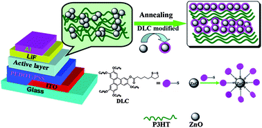
Efficient hybrid solar cells based on a blend of poly(3-hexylthiophene) (P3HT) and discotic liquid crystal ligands dithiol-functionalized triphenylene (TP-S) modified zinc oxide (ZnO) nanoparticles (TP-S@ZnO) were systematically investigated. The TP-S-modified ZnO nanoparticles possess a well-defined dispersibility, especially after annealing under the liquid-crystalline state (130 °C), originating from the help of the supramolecular self-assembly of the TP-S discs. Discotic liquid crystal ligands improve the compatibility between P3HT polymer and ZnO nanoparticles, which is beneficial for enhanced charge separation and transfer efficiency. On the other hand, the interfacial molecules TP-S can play a great role in the ordering and crystallinity of P3HT chains. X-ray diffraction (XRD) and wide-angle X-ray scattering (WAXS) studies indicate that the spontaneous self-assembly of the promotes P3HT chains to overall, the power conversion efficiency (PCE) of polymer/ZnO hybrid solar cells increased from 0.46% to 0.95% after ZnO was modified with TP-S under thermal annealing. As expected, DLC molecular interface modification can provide a viable and interesting method to promote the compatibility and a large interfacial area between polymers and nanocrystals, subsequently improving the performance of photovoltaic devices.

Introduction

Bulk-heterojunction (BHJ) organic photovoltaic devices have drawn much attention in recent years due to their low-cost, mechanical flexibility, easy fabrication and the general applicability of organic materials.1–4 The power conversion efficiency (PCE) in excess of 8% have been reported with fullerene derivatives as the electron acceptors.5,6 An alternative to full-organic solar cells is so-called hybrid solar cell. These devices using conjugated polymers as electron donors and inorganic semiconductor nanocrystals as electron acceptors is also appealing because of the combined merits of both solution processability of conjugated polymers and high electron mobility and morphological stability of inorganic semiconductor nanocrystals.7 Hybrid solar cells based on various nanocrystals such as CdSe, TiO2, and ZnO, have been reported in recent years.8–11 However, CdSe nanocrystal has high toxicity and TiO2 nanocrystal has high crystallization temperature. ZnO nanocrystal is a more promising candidate for use in hybrid solar cell applications, since it is non-toxicity and low crystallization temperature properties.

However, so far the PCE of polymer/ZnO hybrids is still lower than that of full-organic solar cells due to large phase separation between polymer and ZnO nanoparticles (NPs). The efficiency of these BHJ solar cells depends heavily on precise control of nanometer-scale morphology of active layer. Thus, a key challenge for the design of efficient BHJ solar cells is the ability to achieve high-yield and long-lived charge separation at the donor/acceptor interface whilst ensuring good electrical connection between the domains to facilitate charge carrier transport and collection at the device electrodes.12 Recent research have drawn much attention in an emerging field of directly tethering conjugated polymers onto the NPs surface to enhance exciton dissociation and charge transfer at the donor/acceptor interface.13–16 In addition, organic small molecules ligands is a promising approach by attaching the organic ligand molecules through covalently bonding to improve the compatibility between the ZnO NPs and the surrounding polymer, which markedly promotes the dispersion of NPs within the polymer matrix, facilitating the photoinduced charge transfer between these two semiconductor.17,18

Liquid crystals (LCs) have been widely investigated and applied in many areas, such as liquid crystal displays (LCDs),19 organic photovoltaics (OPVs),20,21 because they offer the possibility of creating self-organizing and self-assembling materials that possess both order and mobility at molecular, supramolecular and macroscopic levels.22,23 As of a class of LCs, discotic liquid crystals (DLCs), are particularly attractive for various device applications because the 1D columnar structure, resulting from strong intermolecular interactions between the planar aromatic cores, has been regarded as an efficient pathway for charge transport along the columnar axis.24,25 However, the application of such a DLC in BHJ organic solar cells, though very promising, has not been extensively studied. This situation inspired us to design surface modification of ZnO NPs with DLC ligands to improve and optimize the nanomorphology of polymer/ZnO hybrid by the DLC self-assembly.

In this work, we rationally report the preparation of self-assembled ZnO NPs modified with DLC ligands dithiol-functionalized triphenylene (TP-S). We found that modifying ZnO NPs with liquid-crystalline nature could enable these ZnO NPs to possess an extremely well-defined dispersibility, which exhibits excellent compatibility and a large interfacial area between P3HT and ZnO NPs. Moreover, the liquid-crystalline behavior of ligands TP-S also can improve the ordering of P3HT chains. Overall, we demonstrated that the performance of polymer/ZnO hybrid solar cells have been substantially enhanced from 0.46% to 0.95% by directly grafting the ligands TP-S onto ZnO NPs.

Results and discussion

The targeted dithiol-functionalized triphenylene, namely 2-[(5-(1,2-dithiolan-3-yl)-pentanoate)]-3,6,7,10,11-pentakis(butoxy)triphenylene (TP-S), was prepared according to adapted procedures described in the literature26 (as depicted in Scheme S1). Cyclic voltammetry was used to calculate the frontier molecular orbital energy levels of TP-S (Fig. S2). The highest-occupied molecular orbital (HOMO) and lowest-unoccupied molecular orbital (LUMO) levels are estimated to be −6.1 and −3.6 eV, respectively. The energy levels of TP-S is located at the intermediate between P3HT and ZnO (Fig. 1c), which would provide intimate electronic contact and improve charge transfer between the donor and acceptor.27 The mesomorphic behavior of TP-S has been studied by polarizing optical microscopy (POM) and differential scanning calorimetry (DSC) (Fig. 2). Under POM, a birefringent and multicoloured texture was observed when cooling from the isotropic state, suggesting a liquid-crystalline property of the TP-S discs. DSC experiments confirmed POM observations. The two discrete endothermic peaks at 77 and 137 °C for TP-S are identified as the two transitions involving liquid-crystalline phases.
image file: c3ra44980g-f1.tif
Fig. 1 (A) Chemical structures of 2-[(5-(1,2-dithiolan-3-yl)pentanoate)]-3,6,7,10,11-pentakis(butoxy)triphenylene (TP-S), (B) a ZnO nanoparticle modified with triphenylene ligands (TP-S@ZnO) and (C) the energy level diagram for P3HT, TP-S and ZnO.

image file: c3ra44980g-f2.tif
Fig. 2 DSC thermogram of the TP-S recorded under nitrogen during cooling scans at a scan rate of 10 °C min−1. The mesomorphic textures observed by POM at 130 °C under cooling from isotropic state (cooling rate: 1 °C min−1).

ZnO nanoparticles (NPs) were prepared according to the previous references.3 ZnO NPs surface modification with TP-S (TP-S@ZnO) is done by sonicating the ZnO NPs and the TP-S discs together in ortho-dichlorobenzene for 1 h under N2 atmosphere. The hybrid material is purified by centrifugation and exchange of the solvent for several times to eliminate non-modified ligand molecules. Grafting of TP-S onto the ZnO NPs surfaces was also visualized by optical changes of the solution. Before grafting, ZnO NPs form aggregates in solution as indicated by strong light scattering of the solution (inset image of Fig. 3). When TP-S is bound to ZnO NPs surfaces, the solubility and dispersibility in a TP-S@ZnO hybrid become translucent with respect to the pristine ZnO NPs. The successful attachment of the TP-S to ZnO surface is also confirmed by FT-IR analysis. The characteristic absorptions (O–C[double bond, length as m-dash]O) of the TP-S groups can be observed in TP-S@ZnO hybrid groups (Fig. S3), again undoubtedly proving the occurrence of interface molecular modification on ZnO NPs surfaces. The final weight percentage of TP-S bound to the ZnO NPs surfaces was 5.6 wt% (relative) calculated from the result of thermogravimetric analysis (TGA) (Fig. 3).


image file: c3ra44980g-f3.tif
Fig. 3 TGA thermogram of pure ZnO and TP-S modified ZnO (TP-S@ZnO) under nitrogen at a heating rate of 10 °C min−1. Inset is the optical image of ortho-dichlorobenzene solutions (10 mg ml−1) containing pristine ZnO (left) or TP-S@ZnO (right).

Scanning electron microscopy (SEM) analysis was used to investigate the effect of TP-S liquid-crystalline behaviors on the morphology of ZnO NPs films. Fig. 4a and b shows SEM images of the ZnO NPs and TP-S@ZnO hybrid films after annealing at 130 °C (LC state temperature). Obviously, in the annealed ZnO film, the large-scale ZnO clusters can be observed, suggestive of a significant aggregation of ZnO NPs. In sharp contrast, the annealed TP-S@ZnO hybrid film is homogenous, implying that the supramolecules organizations of TP-S discs in LC state can dramatically favor the dispersibility of ZnO NPs. Atomic force microscope (AFM) analysis further investigated ZnO NPs aggregation and film surface roughness. Fig. 4c and d show the surface morphologies of the pristine ZnO NPs and TP-S@ZnO hybrid films after annealing at 130 °C. The results of AFM images also agree well with the observation in SEM images. It is clear that the annealed ZnO NPs film reveals an obvious coarse surface with the root mean square (RMS) roughness of 31.4 nm. After the surface modification, the annealed TP-S@ZnO hybrid film shows a much smoother surface with a RMS surface roughness of only 16.6 nm, which means that the discotic liquid crystalline ligand play a crucial role in the arrangement of ZnO NPs.


image file: c3ra44980g-f4.tif
Fig. 4 (a and b) SEM and (c and d) AEM images of (a and c) ZnO and (b and d) TP-S@ZnO films after annealing at 130 °C.

Fig. 5 shows the UV-vis absorption spectra of the P3HT/ZnO, and P3HT/TP-S@ZnO blend films before and after thermal treatment at 130 °C, coated on quartz substrates. As can be seen from Fig. 5, the normalized solid-state absorption spectra of these blend films show two characteristic absorption peaks. The peak (330 nm) in the ultraviolet region can be assigned to the ZnO absorption, whereas the band in the visible-light region (510–610 nm) results from the transition of P3HT backbone. The shoulder at 603 nm of these blend films is related to the formation of ordered structures of lamellar π-stacked aggregates, despite the presence of the ZnO NPs. Intriguingly, after thermal treatment at 130 °C, the appearance of almost 10 nm red-shift in P3HT/TP-S@ZnO film is observed, compared to the annealed P3HT/ZnO film. The appearance of red-shifted species is usually due to the formation of crystallites and an indication for more ordered structures.28 In order to gain further insight into the orientation of P3HT chains in thin solid films by discotic mesogen self-assembly, the structure changes of the thin films are investigated by polarized UV-vis absorption spectroscopy. Through the polarization absorption of the annealed P3HT/ZnO and P3HT/TP-S@ZnO films at their maximum absorption peaks, we can conclude the long axis of the molecule arrangement.29 As shown in Fig. 6, the absorption of parallel direction (A) for annealed P3HT/ZnO film show little increases compared to that of the perpendicular direction (A), while a significant increase for annealed P3HT/TP-S@ZnO film. The dichroic ratio (A[thin space (1/6-em)]:[thin space (1/6-em)]A) at the maximum absorption changed from 1.12 for P3HT/ZnO film to 1.36 for P3HT/TP-S@ZnO film. This indicates that the spontaneous self-assembly of TP-S@ZnO in the active layer promotes a more oriented long axis alignment of P3HT chains.


image file: c3ra44980g-f5.tif
Fig. 5 UV-vis absorption spectra of P3HT/ZnO and P3HT/TP-S@ZnO films before and after annealing at 130 °C.

image file: c3ra44980g-f6.tif
Fig. 6 Polarized absorbance spectra of (A) P3HT/ZnO and (B) P3HT/TP-S@ZnO films after annealing at 130 °C. A and A are the absorption intensities in the direction parallel and perpendicular to the P3HT molecule.

The dramatic effect of LC state annealing on the crystallinity of P3HT was also explained by XRD spectra. Fig. 7 shows the XRD profiles of P3HT/ZnO and P3HT/TP-S@ZnO films before and after annealing at 130 °C, all of which exhibited the diffraction peak (100) at 2θ = 5.4° attributed to the inter-P3HT d-spacing of the alkyl side chain,30 and the diffraction peaks in the range of 30–40° arose from crystal structures of ZnO.31 It was interesting to note that a relative higher intensity of diffraction peak (2θ = 5.4°) shows in the annealed P3HT/TP-S@ZnO film than in the pristine P3HT/TP-S@ZnO film, even than the annealed P3HT/ZnO film. After discotic liquid crystal TP-S modification on ZnO surfaces under thermal annealing, although the P3HT aggregations (not crystals) became smaller due to the enhanced dispersibility of TP-S@ZnO, the self-assembly of TP-S@ZnO could induce P3HT chains escaping from the amorphous domains to form highly ordered lamellar packing structures in the active layer.32 The enhanced crystallinity of P3HT might lead to improved exciton dissociation, charge transport and increased photovoltaic performance. As an additional approach, two-dimensional wide-angle X-ray scattering (2D-WAXS) was performed to investigate the ordering of P3HT in the active layer (Fig. 8). The (100) scattering peak at q = 3.7 nm−1 is an indicator of the formation of ordered lamellar packing structures, which is related to the distance of 1.65 nm between the inter-P3HT side chains. Obviously, after LC state temperature (130 °C) annealing treatment, the P3HT/TP-S@ZnO sample appears to broaden more orientation distribution of the polymer lamellar stacking compared to P3HT/ZnO film, as evidenced by the stronger scattering intensity of the (100) peak in Fig. 8. In addition, the (010) peak associated to π–π stacking between P3HT backbones—a critical factor in charge mobility for P3HT—is also observed in 2D WAXS patterns, suggesting a better crystallinity of P3HT chains.


image file: c3ra44980g-f7.tif
Fig. 7 XRD profiles of P3HT/ZnO and P3HT/TP-S@ZnO films before and after annealing at 130 °C.

image file: c3ra44980g-f8.tif
Fig. 8 Two-dimensional wide-angle X-ray scattering (WAXS) patterns and their line plots of P3HT/ZnO and P3HT/TP-S@ZnO films after annealing at 130 °C.

Fig. 9 shows the photoluminescence (PL) emission spectra of P3HT/ZnO and P3HT/TP-S@ZnO films before and after annealing at 130 °C. After the interfacial modification on ZnO NPs surfaces, a reduction in the PL intensity of P3HT/TP-S@ZnO hybrid films relative to that of P3HT/ZnO films is observed, and the PL intensity further decreases after the thermal treatment. This PL quenching behavior can be explained by intermolecular electron transfer from the photoexcited copolymers to the ZnO NPs. These results demonstrated that the efficiency of charge separation at the P3HT/ZnO interfaces had been remarkably improved after the interfacial modification with TP-S, especially after thermal treatment at LC state. The self-assembly of TP-S ligands tends to provide a better pathway for electrons and holes for transporting in the active layer.


image file: c3ra44980g-f9.tif
Fig. 9 Fluorescence spectra of P3HT/ZnO and P3HT/TP-S@ZnO films before and after annealing at 130 °C.

To account for the improved charge separation, the morphologies of P3HT/ZnO hybrids with and without TP-S interfacial modification before and after thermal treatment were investigated by TEM, as shown in Fig. 10. The P3HT/ZnO films, whether annealed or not, ZnO NPs can easily aggregate and show obvious macro-phase segregation patterns involving the dark domains of ZnO NPs and the lighter domains of P3HT polymer, as shown in Fig. 10a and c. This large phase separation between donor and acceptor domains may yield a poor surface area for exciton dissociation and charge carrier generation between the two components.33 However, the P3HT/TP-S@ZnO film before annealing exhibits the phase-separated domains with obviously decreased size, in spite of the existence of some small ZnO NPs aggregation in Fig. 10b. Moreover, this improvement is more notable for the P3HT/TP-S@ZnO film after annealing (Fig. 10d). The annealed P3HT/TP-S@ZnO film was characterized by a slight variation reflecting a rather well-distributed and finer miscibility of P3HT polymer and ZnO NPs, compared to the non-annealed film. From these results, we confirm that the spontaneous self-assembly of DLC ligands TP-S induce a better compatibility of the mixed polymer/ZnO hybrid.


image file: c3ra44980g-f10.tif
Fig. 10 TEM images of the P3HT/ZnO films before (a) and after (c) annealing at 130 °C, and P3HT/TP-S@ZnO films before (b) and after (d) annealing at 130 °C.

Solar cells based on P3HT/ZnO and P3HT/TP-S@ZnO have been characterized with a conventional device configuration ITO/PEDOT:PSS/active layer/LiF/Al. Fig. 11 shows the typical current density–voltage (JV) characteristics under simulated AM 1.5G solar irradiation of the devices, and the device parameters (PCE, VOC, JSC, and FF) are summarized in Table 1. The bulk heterojunction devices based on P3HT/ZnO film without annealing only showed a PCE of 0.46% with a JSC of 2.22 mA cm−2, a VOC of 0.61 V and a FF of 0.34. After annealing at 130 °C, the value of PCE has a slight enhancement up to 0.51%. However, the performance of the device based on TP-S@ZnO/P3HT before annealing showed an obvious improvement with a PCE of 0.70. A further improvement in the device performance is presented by annealing, showing a PCE of 0.95% with a JSC of 4.50 mA cm−2. A comparison of the two systems reveals that the P3HT/TP-S@ZnO exhibited a higher JSC than that of P3HT/ZnO device, consequently resulting in the enhanced device performance. The low JSC for P3HT/ZnO stems from a high device serial resistance caused by the large phase separation morphology, as observed by the TEM images (discuss before). Conversely, the VOC of these devices is not significantly changed, because the VOC in BHJ solar cells mainly dependents on the magnitude of the built-in potential, defined as the difference between the HOMO level of a p-type donor and the LUMO level of an n-type acceptor,34 rather than the change in blend phase separation morphology. This demonstrates that grafting the DLC ligands TP-S onto ZnO NPs surfaces have promoted an optimized morphology of the active layer to allow an enhanced performance of polymer/ZnO hybrid solar cells.


image file: c3ra44980g-f11.tif
Fig. 11 JV characteristics of photovoltaic cells based on P3HT/ZnO hybrid films with and without TP-S interfacial modifications before and after thermal treatment. The inset shows a schematic device configuration of the solar cell.
Table 1 Device performance of as-cast and annealed P3HT/ZnO hybrid solar cells with and without TP-S interfacial modifications
Componentsa VOC (V) JSC (mA cm−2) FF PCEc (%)
a The ratio by mass of P3HT/ZnO hybrids with or without TP-S interfacial modification were kept in 1[thin space (1/6-em)]:[thin space (1/6-em)]2.b Samples are annealed for 10 min at the LC state temperature of TP-S (130 °C).c All values represent averages.
P3HT/ZnO, as-cast 0.61 2.22 0.34 0.46
P3HT/ZnO, annealingb 0.63 2.47 0.33 0.51
P3HT/TP-S@ZnO, as-cast 0.65 3.45 0.31 0.70
P3HT/TP-S@ZnO, annealingb 0.60 4.52 0.35 0.95


Conclusions

In this work, we have synthesized discotic liquid crystal (DLC) ligands dithiol-functionalized triphenylene (TP-S), to modify the ZnO NPs surface in polymer/ZnO hybrid solar cells. The attachment of TP-S onto ZnO NPs surfaces can render the ZnO NPs self-assemble to improve the compatibility between P3HT polymer and ZnO NPs, favoring exciton dissociation and charge carrier generation. At the same time, the order and crystallinity of P3HT chains in the P3HT/TP-S@ZnO hybrid has also enhanced significantly with the help of TP-S mesogen orientation, compared to the pristine P3HT/ZnO hybrid. The higher JSC can be achieved by coordinately optimizing the hybrid film morphology and charge transport property. The power conversion efficiency of the hybrid solar cell increased from 0.46% to 0.95% after TP-S modification on ZnO NPs surfaces upon thermal annealing. The efficiency is still low for practical application. The main reason is that the P3HT and ZnO adopted here have a relatively large band gap that can not efficiently harvest the available sunlight in the solar spectrum. A further improvement of the power conversion efficiency could possibly be realized by combining low-band gap polymer with inorganic nanocrystals quantum rods as the active layer.

Acknowledgements

This work was supported by the National Natural Science Foundation of China (51263016 and 51003045).

References

  1. J. Peet, M. L. Senatore, A. J. Heeger and G. C. Bazan, Adv. Mater., 2009, 21, 1521 CrossRef CAS.
  2. G. Dennler, M. C. Scharber and C. J. Brabec, Adv. Mater., 2009, 21, 1323 CrossRef CAS.
  3. M. Riede, T. Mueller, W. Tress, R. Schueppel and K. Leo, Nanotechnology, 2008, 19, 424001 CrossRef CAS PubMed.
  4. S. H. Park, A. Roy, S. Beaupre, S. Cho, N. Coates, J. S. Moon, D. Moses, M. Leclerc, K. Lee and A. J. Heeger, Nat. Photonics, 2009, 3, 297 CrossRef CAS.
  5. M. A. Green, K. Emery, Y. Hishikawa and W. Warta, Prog. Photovoltaics, 2011, 19, 84 CAS.
  6. L. M. Chen, Z. R. Hong, G. Li and Y. Yang, Adv. Mater., 2009, 21, 1434 CrossRef CAS.
  7. W. U. Huynh, J. J. Dittmer and A. P. Alivisatos, Science, 2002, 295, 2425 CrossRef CAS PubMed.
  8. R. Zhu, C. Y. Jiang, B. Liu and S. Ramakrishna, Adv. Mater., 2009, 21, 994 CrossRef CAS.
  9. D. J. D. Moet, L. J. A. Koster, B. de Boer and P. W. M. Blom, Chem. Mater., 2007, 19, 5856 CrossRef CAS.
  10. S. Y. Shao, F. M. Liu, Z. Y. Xie and L. X. Wang, J. Phys. Chem. C, 2010, 114, 9161 CAS.
  11. W. J. E. Beek, M. M. Wienk and A. J. R. Janssen, Adv. Funct. Mater., 2006, 16, 1112 CrossRef CAS.
  12. G. Yu, J. Gao, J. C. Hummelen, F. Wudl and A. J. Heeger, Science, 1995, 270, 1789 CAS.
  13. L. Zhao and Z. Lin, Adv. Mater., 2012, 24, 4353 CrossRef CAS PubMed.
  14. D. Gebeyehu, C. J. Brabec, N. S. Sariciftci, D. Vangeneugden, R. Kiebooms, D. Vanderzande, F. Kienberger and H. Schindler, Synth. Met., 2002, 125, 279 CrossRef CAS.
  15. Z. Yin, S. Wu, X. Zhou, X. Huang, Q. Zhang, F. Boey and H. Zhang, Small, 2010, 6, 307 CrossRef CAS PubMed.
  16. M. He, F. Qiu and Z. Lin, J. Phys. Chem. Lett., 2013, 4, 1788 CrossRef CAS.
  17. D. Costenaro, F. Carniato, G. Gatti, L. Marchese and C. Bisio, New J. Chem., 2013, 37, 2103 RSC.
  18. D. Costenaro, F. Carniato, G. Gatti, C. Bisio and L. Marchese, J. Phys. Chem. C, 2011, 115, 25257 CAS.
  19. H. Yu, T. Kobayashi and H. Yang, Adv. Mater., 2011, 23, 3337 CrossRef CAS.
  20. T. Yasuda, H. Ooi, J. Morita, Y. Akama, K. Minoura, M. Funahashi, T. Shimomura and T. Kato, Adv. Funct. Mater., 2009, 19, 411 CrossRef CAS.
  21. L. J. Martínez-Miranda, K. M. Traister, I. Meléndez-Rodríguez and L. Salamanca-Riba, Appl. Phys. Lett., 2010, 97, 223301 CrossRef PubMed.
  22. L. J. Martínez-Miranda and L. K. Kurihara, J. Appl. Phys., 2009, 105, 084305 CrossRef PubMed.
  23. S. P. Diring, F. Camerel, B. Donnio, T. Dintzer, S. Toffanin, R. Capelli, M. Muccini and R. Ziessel, J. Am. Chem. Soc., 2009, 131, 18177 CrossRef CAS PubMed.
  24. S. Sergeyev, W. Pisula and Y. H. Geerts, Chem. Soc. Rev., 2007, 36, 1902 RSC.
  25. J. H. Lee, H. S. Kim, B. D. Pate and S. M. Choi, Phys. B, 2006, 798, 385 Search PubMed.
  26. J. L. Schulte, S. Laschat, V. Vill, E. Nishikawa, H. Finkelmann and M. Nimtz, Eur. J. Org. Chem., 1998, 2499 CrossRef CAS.
  27. G. K. Mor, S. Kim, M. Paulose, O. K. Varghese, K. Shankar, J. Basham and C. A. Grimes, Nano Lett., 2009, 9, 4250 CrossRef CAS PubMed.
  28. E. Lee, B. Hammer, J.-K. Kim, Z. Page, T. Emrick and R. C. Hayward, J. Am. Chem. Soc., 2011, 133, 10390 CrossRef CAS PubMed.
  29. K. Okano, Y. Mikami, M. Hidaka and T. Yamashita, Macromolecules, 2011, 44, 5605 CrossRef CAS.
  30. T. A. Chen, X. M. Wu and R. D. Rieke, J. Am. Chem. Soc., 1995, 117, 233 CrossRef CAS.
  31. Y.-Y. Lin, Y.-Y. Lee, L. Chang, J.-J. Wu and C.-W. Chen, Appl. Phys. Lett., 2009, 94, 063308 CrossRef PubMed.
  32. S. Jeong, Y. Kwon, B.-D. Choi, G. Kwak and Y. S. Han, Macromol. Chem. Phys., 2010, 211, 2474 CrossRef CAS.
  33. C. J. Brabec, M. Heeney, I. McCulloch and J. Nelson, Chem. Soc. Rev., 2011, 40, 1185 RSC.
  34. M. Lenes, G.-J. A. H. Wetzelaer, F. B. Kooistra, S. C. Veenstra, J. C. Hummelen and P. W. M. Blom, Adv. Mater., 2008, 20, 2116 CrossRef CAS.

Footnote

Electronic supplementary information (ESI) available. See DOI: 10.1039/c3ra44980g

This journal is © The Royal Society of Chemistry 2014