Carbon aerogels electrode with reduced graphene oxide additive for capacitive deionization with enhanced performance
Yong
Liu
a,
Chunyang
Nie
b,
Likun
Pan
*a,
Xingtao
Xu
a,
Zhuo
Sun
a and
Daniel H. C.
Chua
c
aEngineering Research Center for Nanophotonics & Advanced Instrument, Ministry of Education, Shanghai Key Laboratory of Magnetic Resonance, Department of Physics, East China Normal University, Shanghai 200062, China. E-mail: lkpan@phy.ecnu.edu.cn; Fax: +86 21 62234321; Tel: +86 21 62234132
bUniversité Paul Sabatier CIRIMAT-LCMIE CIRIMAT 118, Route de Narbonne 31062, Toulouse cedex 09, France
cDepartment of Materials Science and Engineering, National University of Singapore, Singapore 117574, Singapore
First published on 12th February 2014
Abstract
Carbon aerogels (CAs) electrodes with reduced graphene oxide (RGO) additive were fabricated and used as electrosorption electrodes. The capacitive deionization (CDI) performance of the CAs electrodes with different proportions of RGO was investigated. The results show that the CAs electrodes with RGO additive exhibit better electrosorption performance compared with pure CAs electrodes and an electrode with acetylene black additive, indicating that RGO can serve as a flexible bridge to form a “plane-to-point” (RGO-to-CAs) conducting network, which can improve the electron transfer within the CAs electrode. The CAs electrode with 15 wt% RGO was further used in membrane capacitive deionization which integrates ion-exchange membranes with CDI and an extremely high desalination efficiency of 98% was obtained.
Introduction
Membrane capacitive deionization (MCDI) proposed by Lee et al.,1 which integrates ion-exchange membranes with traditional capacitive deionization (CDI), is a water purification technology which is receiving more and more interest because it exhibits a much higher salt removal capacity than CDI.2–9 During conventional CDI processes, when an electric potential (normally up to 1.5 V and in some work, at the cost of significant water splitting, up to 2 V) is applied to electrodes, counter-ions adsorption and co-ions expulsion effects happen simultaneously, which leads to a higher energy consumption and a lower operation efficiency.10 To solve this problem, MCDI, as an advanced version of CDI, is suggested in which cation-exchange membrane and anion-exchange membrane selectively permeable to cations and anions, serving as charge barriers, are introduced in front of the cathode and anode, respectively. The ions, with charge as the electrode, are prevented from moving out of the electrode film, and thus the desalination efficiency is enhanced. Compared with other membrane technology such as reverse osmosis and electrodialysis, MCDI has an additional advantage in that it does not form a sustained concentrate which will cause fouling problems as the concentrate is flushed out before the fouling.In CDI and MCDI devices, the electrode materials are regarded as the most important component because the device efficiency strongly depends upon the properties of electrode materials. Conventionally, carbon materials, such as carbon aerogels (CAs),11–14 activated carbons,15–18 carbon nanotubes,19–21 carbon nanotubes and nanofibers composite,22,23 ordered mesoporous carbons,24–27 and electrospun carbon fibers,28–30 have been widely used as CDI electrodes due to their large surface area, high chemical stability and environmental friendliness.31–33 Among these materials, CAs have aroused much attention of researchers as promising available materials for the CDI process. These unique porous materials consist of interconnected, uniform carbonaceous particles (3–30 nm) with small interstitial pores (<50 nm). Such a continuous, monolithic structure leads to a very high Brunauer Emmett Teller (BET) specific surface area (400–1100 m2 g−1) and good electrical conductivity (25–100 S cm−1). These excellent characteristics of CAs make a significant contribution to their electrosorption capacity.
It is well known that traditionally acetylene black (AB) is used in the fabrication of various types of electrodes, including CAs electrodes, due to its good conductivity.35,36 Recently, graphene, an atom-thick two-dimensional carbon nanostructure, with excellent electrical, conductive and mechanical properties has gained interest.37,38 Chemical approaches via reduction of graphite oxide (GO), for the large-scale production of graphene (normally called reduced graphene oxide (RGO)) sheets, have become reality.39 A recent study40 showed that RGO films with high specific surface area of 2400 m2 g−1 and high in-plane electrical conductivity of 5880 S m−1 from KOH activation could be obtained and used for high-power supercapacitors. Therefore, RGO can be considered as a new kind of conductive additive used in the fabrication of CAs electrodes. Moreover, compared with commonly used AB, the layered structure of RGO can form an effective “plane-to-point” (RGO-to-CAs) conducting network, as shown in Fig. 1, which is beneficial to the improvement of the electron transfer within the CAs electrodes.41
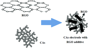 | ||
| Fig. 1 Structure illustration of CAs electrode with RGO additive.34 | ||
In this work, the CDI performance of CAs electrodes with different proportions of RGO additive was investigated and the optimum proportion of RGO was found to be 15 wt%. Furthermore, the desalination performance of the MCDI device based on an optimized electrode was evaluated at various initial conductivities and operating voltages.
Experimental
RGO was prepared using a method reported in our previous work42 as follows: GO dispersion solution was synthesized by a modified Hummer method and the reduction of GO was carried out by adding hydrazine for 24 h at a temperature of 353 K. After being filtered and washed with deionized water, the obtained RGO, consisting of three or four carbon layers,42 was dried in vacuum oven at 333 K. CAs were obtained from Tongji University and detailed information about the fabrication process can be found in their previous work.43,44The carbon materials (CAs), additive (RGO) and binder (polytetrafluoroethene) were mixed and milled for several hours to get a homogeneous mixture in order to ensure firm adhesion between the carbon mixture and graphite substrate. The total mass of an electrode was 0.5 g. Successively, ethanol (10–20 ml) was added dropwise into the mixture and the mixture was then pressed on the graphite paper (8.5 cm × 8.5 cm). Finally, the electrodes were assembled into a CDI or MCDI unit cell. The weight percentages of RGO in the electrodes were 0, 5, 10, 15 and 20 wt%, while the binder was kept at a constant percentage of 10 wt%. For comparison, the CAs electrodes with 15 wt% AB additive were fabricated following the same method.
The morphology and structure of the samples were characterized by a field-emission scanning electron microscopy (FESEM, Hitachi S-4800), and a high-resolution transmission electron microscopy (HRTEM, JEOL-2010), respectively. The N2 adsorption–desorption isotherms used to characterize the porosity of the electrode materials were performed with a Micromeritics TriStar 3000. All samples were heated in a vacuum oven for one day before the measurements. The pore size distribution curve was calculated by the Barrett–Joyner–Halenda (BJH) method from the desorption branch. The specific surface area was calculated from the adsorption data in the relative pressure interval from 0.04 to 0.2 using the BET method. The potential sweep cyclic voltammetry (CV) measurement was carried out in 1 M KCl solution by using Autolab PGSTAT 302N electrochemical workstation in a three-electrode mode, including a standard calomel electrode as reference electrode and platinum foil as counter electrode. The specific capacitance (Csp in F g−1) can be obtained from the CV process according to the equation:
 | (1) |
The ion-exchange membranes were purchased from Tingrun Membrane Co., Ltd (Beijing, China). The cation-exchange membrane is selectively permeable to cations and the anion-exchange membrane is selectively permeable to anions. Their main characteristics are listed in Table 1.
| Cation-exchange membrane | Anion-exchange membrane | |
|---|---|---|
| Thickness (mm) | 0.2 | 0.2 |
| Resistance of surface (Ω cm2) | 1–3 | 4–8 |
| Chemistry stability (pH) | 1–10 | 1–10 |
| Permselectivity (%) | 95–99 | 90–95 |
| Water uptake (%) | 35–43 | 24–30 |
| Ion exchange capacity (meq g−1) | 2.0–2.9 | 1.8–2.2 |
Batch-mode experiments, as described in previous work,5 were conducted in a continuous recycling system including a CDI or MCDI unit cell.4 The spacing of 1 mm between the electrodes is maintained by a nylon spacer. In each experiment, the solution with a total volume of 75 ml was continuously pumped into the cell by a peristaltic pump and the effluent returned to the unit cell. The solution temperature was kept at 298 K and a flow rate around 40 ml min−1 was applied. Analytically pure sodium chloride (NaCl) was used for the aqueous solutions. The relationship between conductivity and concentration was obtained according to a calibration table made prior to the experiment, which has been described in our previous work.41 The concentration variation was continuously monitored and measured at the outlet of the unit cell by using an ion conductivity meter. The experimental data in this work were obtained after several complete electrosorption/desorption cycles when the electrosorption process became stable. The desalination efficiency is defined as follow:
| Desalination efficiency = (C0 − Ce)/C0 | (2) |
Results and discussion
Fig. 2(a)–(e) show the FESEM images of CAs, RGO, AB, CAs with 15 wt% RGO additive and CAs with 15 wt% AB additive, respectively. It is clearly observed from Fig. 2(a) that the CAs present a three-dimensional framework structure consisting of carbonaceous particles. Such a highly porous network structure provides more tunnels for penetration by solutions and allows easy access by ions. The transparent, corrugated and scrolled RGO sheets shown in Fig. 2(b) interact with each other and form an open pore system. A chain-like structure comprised of AB particles can be observed in Fig. 2(c). AB has a partially graphitized structure with some nanopores in the particles, which suggests that its properties are intermediate between those of graphite and amorphous carbon.45 When RGO is added into the CAs matrix, as illustrated in Fig. 2(d), carbonaceous particles of CAs are scattered on the surface of RGO sheets which bridge the gaps between the carbon particles and therefore improve the electrical conductivity of CAs electrodes. In Fig. 2(e), a cluster consisting of AB particles and CAs particles is observed. Obviously, the “plane-to-point” (RGO-to-CAs) conducting network can provide more electrical contact sites than the “point-to-point” (AB-to-CAs) conducting network. The TEM image of CAs with 15 wt% RGO additive in Fig. 2(f) shows that the surface of RGO sheets is bestowed with a great deal of CAs. It is confirmed that a good contact between RGO and CAs is formed, which favors the electron transfer between them.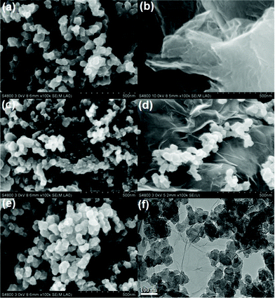 | ||
| Fig. 2 FESEM images of (a) CAs, (b) RGO, (c) AB, (d) CAs with 15 wt% RGO and (e) CAs with 15 wt% AB; (f) TEM image of CAs with 15 wt% RGO. | ||
Fig. 3 displays the N2 adsorption–desorption isotherms of CAs, CAs with 15 wt% AB, and CAs with 15 wt% RGO, respectively. It is clearly observed that all isotherms show typical type IV behavior.46 The N2 adsorption–desorption isotherm and textural properties of RGO can be found in our previous work.41Table 2 summarizes the BET surface areas, micropore volumes, total pore volumes and average pore sizes of CAs, CAs with 15 wt% RGO, and CAs with 15 wt% AB. It can be seen that CAs exhibit a highest specific surface area (948.2 m2 g−1) but the proportion of micropore volume in the total pore volume reaches 45.3%. When RGO with low specific surface area (407 m2 g−1) is introduced into the CAs, the specific surface area and the proportion of micropore decrease to 648.4 m2 g−1 and 31.8% while corresponding values for CAs with AB additive are 625 m2 g−1 and 35.5%, respectively. The average pore sizes of CAs, CAs with 15 wt% RGO, and CAs with 15 wt% AB are 3.15 nm, 3.96 nm, 3.59 nm, respectively. Based on IUPAC classification, the pore size is divided into three groups: micropores (pore width <2 nm), mesopores (between 2 and 50 nm), and macropores (>50 nm). Therefore, CAs with RGO additive consists of more mesopores than CAs and CAs with AB additive, which can alleviate the overlapping effect caused by micropore and will be beneficial to the electrosorption.47–49
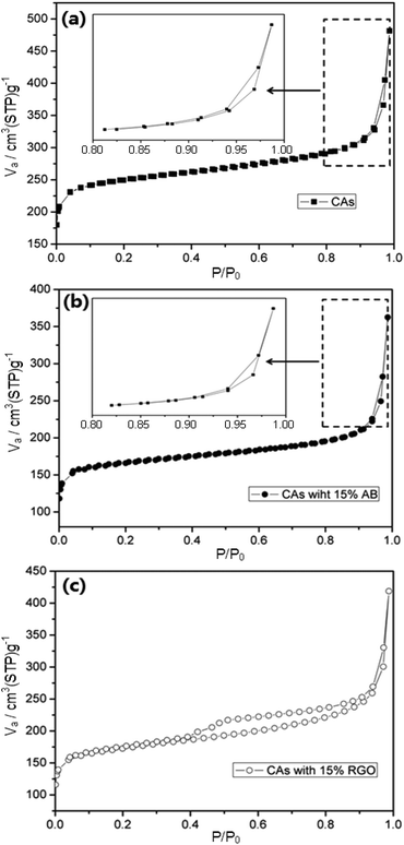 | ||
| Fig. 3 Nitrogen adsorption–desorption isotherms of (a) CAs, (b) CAs with 15% AB and (c) CAs with 15% RGO, respectively. The insets in (a) and (b) are selected areas with higher magnification. | ||
| Sample | S BET (m2 g−1) | V total (cm3 g−1) | V micro (cm3 g−1) | Poreave (nm) |
|---|---|---|---|---|
| CAs | 948.2 | 0.75 | 0.34 | 3.15 |
| 15 wt% RGO | 648.4 | 0.66 | 0.21 | 3.96 |
| 15 wt% AB | 625 | 0.62 | 0.22 | 3.59 |
Fig. 4 shows the CV curves of CAs electrodes with different proportions of RGO and CAs electrode with 15 wt% AB additive at a potential sweep rate of 5 mV s−1 within a potential range of −0.5–0.5 V. All CV curves are nearly rectangular. The current increases and decreases steadily with the electric potential, indicating that no faradaic reaction happens and ions are adsorbed on the electrode surface by forming an electric double layer. The specific capacitances of electrodes with 0, 5, 10, 15, 20 wt% RGO and 15 wt% AB are 69.52, 89.66, 92.43, 101.54, 99.12 and 94.15 F g−1, respectively. The CAs electrode with 15 wt% RGO shows a highest specific capacitance.
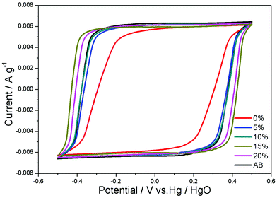 | ||
| Fig. 4 CV curves of CAs electrodes with different proportions of RGO and CAs electrode with 15 wt% AB additive in 1 M KCl solution at a scan rate of 5 mV s−1. | ||
Fig. 5 depicts the CDI process of CAs electrodes with different proportions of RGO and CAs electrode with 15 wt% AB additive in NaCl solutions with an initial conductivity around 100 μS cm−1. The electrosorption voltage is set at 1.2 V. It can be seen that once the voltage is imposed, ions are driven onto the electrodes and the conductivity decreases dramatically and reaches equilibrium after about 30 min. Then the electrodes are shorted for regeneration. The desalination efficiency of pure CAs electrodes is 46.9%. With the addition of RGO into CAs, the NaCl removal is improved, which is attributed to the formation of a three-dimensional network to facilitate the ion transport onto the electrode surface. The CAs electrode with 15 wt% RGO exhibits the highest desalination efficiency of 59%. Therefore, the CAs electrode used in the following experiments is referred to the electrode with 15 wt% RGO additive except for special indication. When RGO content is further increased, the desalination efficiency decreases due to the lower specific surface area of RGO than that of CAs. Furthermore, excessive RGO will cover most of the CAs surface and reduce the electrosorption sites, resulting in low desalination efficiency. The NaCl desalination efficiency of CAs electrode with 15 wt% of AB additive was also investigated. It can be observed that the addition of AB contributes little to the electrosorption performance of CAs electrode. By comparison, it can be concluded that the “plane-to-point” (RGO-to-CAs) conducting network works more effectively than the “point-to-point” (AB-to-CAs) conducting network and therefore enhances the electrosorption capacity of CAs electrode.
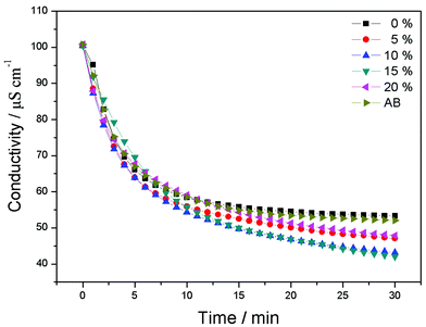 | ||
| Fig. 5 CDI process of CAs electrodes with different proportions of RGO and CAs electrode with 15 wt% AB additive in NaCl solutions with an initial conductivity around 100 μS cm−1. | ||
The desalination performance of a CAs electrode based MCDI was compared with the CDI under the same experimental conditions and the result is shown in Fig. 6. Apparently, the desalination efficiency of MCDI (about 98%) is much higher than that of CDI (about 59%). It indicates that the presence of ion-exchange membranes in MCDI is very helpful for the electrosorption of salt ions through making the counter-ions transfer faster and be absorbed by electrodes without the obstruction of co-ions, which is confirmed by a steeper slope of the electrosorption curve for MCDI in Fig. 6. Different from CDI, the regeneration of MCDI can be completed by reversing the polarization of the electrodes without the appearance of reverse electrosorption because of the existence of ion-exchange membranes. The conductivity comes back to the initial value in much shorter time than that for CDI.
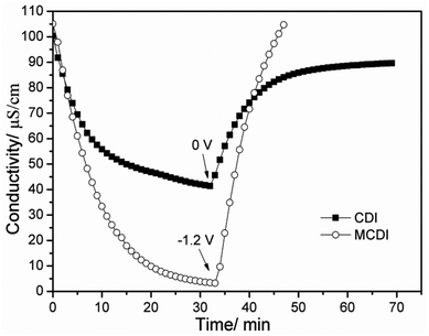 | ||
| Fig. 6 Desalination performance of the CAs electrode based CDI and MCDI in NaCl solutions with an initial conductivity around 100 μS cm−1 at a voltage of 1.2 V. | ||
To further investigate the electrosorption behavior of a CAs electrode based MCDI cell, repeat charge–discharge experiments were carried out in NaCl solution with an initial solution conductivity of 100 μS cm−1 under 1.2 V and the corresponding current was monitored spontaneously, as shown in Fig. 7. Obviously, the repeatability of electrosorption process can be realized in this unit cell. In the practical experiment, electrosorption capacity declination has not been observed in this unit cell after over 30 charge–discharge experiments.
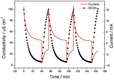 | ||
| Fig. 7 Recycle electrosorption experiment for the CAs electrode based MCDI cell and the corresponding current. | ||
Charge efficiency5,50 is a functional tool to gain insight into the double layer formed at the interface between the electrode and solution. Ideally, if each electron is fully charge balanced by counter-ion adsorption, the transfer of an electron from one electrode to another is accompanied by the removal of one salt molecule from the bulk solution. In this case, the charge efficiency is equal to 1. However, the charge efficiency is less than 1, probably due to co-ion impaction, high transient resistivity and weak conductivity of the porous electrode.
The charge efficiency (Λ) is obtained according to the following equation:
 | (3) |
![[thin space (1/6-em)]](https://www.rsc.org/images/entities/char_2009.gif) 485 C mol−1), Γ is the electrosorption capacity (mol g−1) and Σ (charge, C g−1) is obtained by integrating the corresponding current. The Λ of the CAs electrode based MCDI cell is calculated to be around 0.52.
485 C mol−1), Γ is the electrosorption capacity (mol g−1) and Σ (charge, C g−1) is obtained by integrating the corresponding current. The Λ of the CAs electrode based MCDI cell is calculated to be around 0.52.
Conclusions
In summary, CAs electrodes with RGO additive were fabricated and used as CDI and MCDI electrodes. It is found that (i) a CAs electrode with 15 wt% RGO exhibits an optimum desalination efficiency of 59% in CDI process, which is higher than that of CAs electrode with 15 wt% AB. It indicates that the “plane-to-point” (RGO-to-CAs) conducting network works more effectively than the “point-to-point” (AB-to-CAs) conducting network and therefore enhances the electrosorption capacity of CAs electrodes; (ii) compared with CDI, the desalination efficiency of MCDI is improved to 98% in NaCl solutions with an initial conductivity around 100 μS cm−1 owing to the reduction of co-ion repulsion effect with the introduction of ion-exchange membranes; (iii) no obvious decline in desalination efficiency has been observed in a CAs electrode based MCDI cell during charge–discharge experiments, indicating an excellent regeneration ability.Acknowledgements
Financial support from the National Natural Science Foundation of China (no. 21276087) is gratefully acknowledged. The kind provision of CAs from Mr Dong Liu and Prof. Jun Shen at Shanghai Key Laboratory of Special Microstructure Materials and Technology, Tongji University is gratefully acknowledged.Notes and references
- J. B. Lee, K. K. Park, H. M. Eum and C. W. Lee, Desalination of a thermal power plant wastewater by membrane capacitive deionization, Desalination, 2006, 196, 125–134 CrossRef CAS PubMed.
- M. D. Andelman, Flow through capacitor basics, Sep. Purif. Technol., 2011, 80, 262–269 CrossRef CAS PubMed.
- J. H. Lee and J. H. Choi, The production of ultrapure water by membrane capacitive deionization (MCDI) technology, J. Membr. Sci., 2012, 409–410, 251–256 CrossRef CAS PubMed.
- H. B. Li, Y. Gao, L. K. Pan, Y. P. Zhang, Y. W. Chen and Z. Sun, Electrosorptive desalination by carbon nanotubes and nanofibres electrodes and ion-exchange membranes, Water Res., 2008, 42, 4923–4928 CrossRef CAS PubMed.
- S. Porada, R. Zhao, A. van der Wal, V. Presser and P. M. Biesheuvel, Review on the Science and Technology of Water Desalination by Capacitive Deionization, Prog. Mater. Sci., 2013, 58, 1388–1442 CrossRef CAS PubMed.
- R. Zhao, S. Porada, P. M. Biesheuvel and A. van der Wal, Energy consumption in membrane capacitive deionization for different water recoveries and flow rates and comparison with reverse osmosis, Desalination, 2013, 330, 35–41 CrossRef CAS PubMed.
- R. Zhao, O. Satpradit, H. H. M. Rijnaarts, P. M. Biesheuvel and A. van der Wal, Optimization of Salt Adsorption Rate in Membrane Capacitive Deionization, Water Res., 2013, 47, 1941–1952 CrossRef CAS PubMed.
- R. Zhao, P. M. Biesheuvel and A. van der Wal, Energy Consumption and Constant Current Operation in Membrane Capacitive Deionization, Energy Environ. Sci., 2012, 5, 9520–9527 CAS.
- R. Zhao, S. Porada, P. M. Biesheuvel and A. van der Wal, Energy consumption in membrane capacitive deionization for different water recoveries and flow rates, and comparison with reverse osmosis, Desalination, 2013, 330, 35–41 CrossRef CAS PubMed.
- P. M. Biesheuvel and A. van der Wal, Membrane capacitive deionization, J. Membr. Sci., 2010, 346, 256–262 CrossRef CAS PubMed.
- J. C. Farmer, D. V. Fix, G. V. Mack, R. W. Pekala and J. F. Poco, Capacitive deionization of NaCl and NaNO3 with carbon aerogel electrodes, J. Electrochem. Soc., 1996, 143, 159–169 CrossRef CAS PubMed.
- C. J. Gabelich, T. D. Tran and I. H. M. Suffet, Electrosorption of inorganic salts from aqueous solution using carbon aerogels, Environ. Sci. Technol., 2002, 36, 3010–3019 CrossRef CAS.
- P. Xu, J. E. Drewes, D. Heil and G. Wang, Treatment of brackish produced water using carbon aerogel-based capacitive deionization technology, Water Res., 2008, 42, 2605–2617 CrossRef CAS PubMed.
- H. H. Jung, S. W. Hwang, S. H. Hyun, L. Kang-Ho and G. T. Kim, Capacitive deionization characteristics of nanostructured carbon aerogel electrodes synthesized via ambient drying, Desalination, 2007, 216, 377–385 CrossRef CAS PubMed.
- Y. J. Kim and J. H. Choi, Enhanced desalination efficiency in capacitive deionization with an ion-selective membrane, Sep. Purif. Technol., 2010, 71, 70–75 CrossRef CAS PubMed.
- Y. J. Kim and J. H. Choi, Improvement of desalination efficiency in capacitive deionization using a carbon electrode coated with an ion-exchange polymer, Water Res., 2010, 44, 990–996 CrossRef CAS PubMed.
- P. M. Biesheuvel, Y. Fu and M. Z. Bazant, Diffuse charge and Faradaic reactions in porous electrodes, Phys. Rev. E: Stat. Phys., Plasmas, Fluids, Relat. Interdiscip. Top., 2011, 83, 061507 CrossRef CAS.
- J. Y. Lee, S. J. Seo, S. H. Yun and S. H. Moon, Preparation of ion exchanger layered electrodes for advanced membrane capacitive deionization (MCDI), Water Res., 2011, 45, 5357–5380 Search PubMed.
- L. Wang, M. Wang, Z. H. Huang, T. X. Cui, X. C. Gui, F. Y. Kang, K. L. Wang and D. H. Wu, Capacitive deionization of NaCl solutions using carbon nanotube sponge electrodes, J. Mater. Chem., 2011, 21, 18295–18299 RSC.
- C. Y. Nie, L. K. Pan, H. B. Li, T. Q. Chen, T. Lu and Z. Sun, Electrophoretic deposition of carbon nanotubes film electrodes for capacitive deionization, J. Electroanal. Chem., 2012, 666, 85–88 CrossRef CAS PubMed.
- D. S. Zhang, T. T. Yan, L. Y. Shi, Z. Peng, X. Wen and J. P. Zhang, Enhanced capacitive deionization performance of graphene/carbon nanotube composites, J. Mater. Chem., 2012, 22, 14696–14704 RSC.
- X. Z. Wang, M. G. Li, Y. W. Chen, R. M. Cheng, S. M. Huang, L. K. Pan and Z. Sun, Electrosorption of ions from aqueous solutions with carbon nanotubes and nanofibers composite film electrodes, Appl. Phys. Lett., 2006, 89, 053127 CrossRef PubMed.
- H. B. Li, L. K. Pan, Y. P. Zhang, L. D. Zou, C. Q. Sun, Y. K. Zhan and Z. Sun, Kinetics and thermodynamics study for electrosorption of NaCl onto carbon nanotubes and carbon nanofibers electrodes, Chem. Phys. Lett., 2010, 485, 161–166 CrossRef CAS PubMed.
- L. Zou, L. Li, H. Song and G. Morris, Using mesoporous carbon electrodes for brackish water desalination, Water Res., 2008, 42, 2340–2348 CrossRef CAS PubMed.
- C. Tsouris, R. Mayes, J. Kiggans, K. Sharma, S. Yiacoumi, D. DePaoli and S. Dai, Mesoporous carbon for capacitive deionization of saline water, Environ. Sci. Technol., 2011, 45, 10243–10249 CrossRef CAS PubMed.
- Z. Peng, D. S. Zhang, L. Y. Shi and T. T. Yan, High performance ordered mesoporous carbon/carbon nanotube composite electrodes for capacitive deionization, J. Mater. Chem., 2012, 22, 6603–6612 RSC.
- D. S. Zhang, X. R. Wen, L. Y. Shi, T. T. Yan and J. P. Zhang, Enhanced capacitive deionization of graphene/mesoporous carbon composites, Nanoscale, 2012, 4, 5440–5446 RSC.
- M. Wang, Z. H. Huang, L. Wang, M. X. Wang, F. Kang and H. Hou, Electrospun ultrafine carbon fiber webs for electrochemical capacitive desalination, New J. Chem., 2010, 34, 1843–1845 RSC.
- G. Wang, Q. Dong, Z. Ling, C. Pan, C. Yu and J. Qiu, Hierarchical activated carbon nanofiber webs with tuned structure fabricated by electrospinning for capacitive deionization, J. Mater. Chem., 2012, 22, 21819–21823 RSC.
- G. Wang, C. Pan, L. Wang, Q. Dong, C. Yu, Z. Zhao and J. Qiu, Activated carbon nanofiber webs made by electrospinning for capacitive deionization, Electrochim. Acta, 2012, 69, 65–70 CrossRef CAS PubMed.
- E. Avraham, M. Noked, Y. Bouhadana, A. Soffer and D. Aurbach, Limitations of charge efficiency in capacitive deionization processes III: The behavior of surface oxidized activated carbon electrodes, Electrochim. Acta, 2010, 56, 441–447 CrossRef CAS PubMed.
- P. Hojati-Talemi, L. Zou, M. Fabretto and R. D. Short, Using oxygen plasma treatment to improve the performance of electrodes for capacitive water deionization, Electrochim. Acta, 2013, 106, 494–499 CAS.
- Y. Wimalasiri and L. Zou, Carbon nanotube/graphene composite for enhanced capacitive deionization performance, Carbon, 2013, 59, 464–471 CrossRef CAS PubMed.
- C. Y. Nie, D. Liu, L. K. Pan, Y. Liu, Z. Sun and J. Shen, Enhanced capacitive behavior of carbon aerogels/reduced graphene oxide composite film for supercapacitors, Solid State Ionics, 2013, 247, 66–70 CrossRef PubMed.
- F. C. Meng, X. T. Zhang, B. Xu, S. F. Yue, H. Guo and Y. J. Luo, Alkali-treated graphene oxide as a solid base catalyst: synthesis and electrochemical capacitance of graphene/carbon composite aerogels, J. Mater. Chem., 2011, 21, 18537–18539 RSC.
- H. C. Shin, W. Cho and H. Jang, Electrochemical properties of carbon-coated LiFePO4 cathode using graphite, carbon black, and acetylene black, Electrochim. Acta, 2006, 52, 1472–1476 CrossRef CAS PubMed.
- D. A. Dikin, S. Stankovich, E. J. Zimney, R. D. Piner, G. H. B. Dommett, G. Evmenenko, S. T. Nguyen and R. S. Ruoff, Preparation and characterization of graphene oxide paper, Nature, 2007, 448, 457–460 CrossRef CAS PubMed.
- Y. W. Zhu, S. Murali, W. W. Cai, X. S. Li, J. W. Suk, J. R. Potts and R. S. Ruoff, Graphene and Graphene Oxide: Synthesis, Properties, and Applications, Adv. Mater., 2010, 22, 3906–3924 CrossRef CAS PubMed.
- M. Choucair, P. Thordarson and J. A. Stride, Gram-scale production of graphene based on solvothermal synthesis and sonication, Nat. Nanotechnol., 2009, 4, 30–33 CrossRef CAS PubMed.
- L. L. Zhang, X. Zhao, M. D. Stoller, Y. W. Zhu, H. X. Ji, S. Murali, Y. P. Wu, S. Perales, B. Clevenger and R. S. Ruoff, Highly Conductive and Porous Activated Reduced Graphene Oxide Films for High-Power Supercapacitors, Nano Lett., 2012, 12, 1806–1812 CrossRef CAS PubMed.
- H. B. Li, L. K. Pan, C. Y. Nie, Y. Liu and Z. Sun, Reduced graphene oxide and activated carbon composites for capacitive deionization, J. Mater. Chem., 2012, 22, 15556–15561 RSC.
- H. B. Li, T. Lu, L. K. Pan, Y. P. Zhang and Z. Sun, Electrosorption behavior of graphene in NaCl solutions, J. Mater. Chem., 2009, 19, 6773–6779 RSC.
- J. Shen, J. Q. Hou, Y. Z. Guo, H. Xue, G. M. Wu and B. Zhou, Microstructure control of RF and carbon aerogels prepared by sol-gel process, J. Sol–Gel Sci. Technol., 2005, 36, 131–136 CrossRef CAS.
- J. Shen and J. Wang, Carbon aerogel films synthesized at ambient conditions, J. Sol–Gel Sci. Technol., 2004, 31, 209–213 CrossRef CAS.
- B. Zhang, C. Lai, Z. Zhou and X. P. Gao, Preparation and electrochemical properties of sulfur–acetylene black composites as cathode materials, Electrochim. Acta, 2009, 54, 3708–3713 CrossRef CAS PubMed.
- M. Kruk and M. Jaroniec, Gas adsorption characterization of ordered organic–inorganic nanocomposite materials, Chem. Mater., 2001, 13, 3169–3183 CrossRef CAS.
- C. H. Hou, C. D. Liang, S. Yiacoumi, S. Dai and C. Tsouris, Electrosorption capacitance of nanostructured carbon-based materials, J. Colloid Interface Sci., 2006, 302, 54–61 CrossRef CAS PubMed.
- K. L. Yang, T. Y. Ying, S. Yiacoumi, C. Tsouris and E. S. Vittoratos, Electrosorption of Ions from Aqueous Solutions by Carbon Aerogel: An Electrical Double-Layer Model, Langmuir, 2001, 17, 1961–1969 CrossRef CAS.
- Y. Show and K. Imaizumi, Electric double layer capacitor with low series resistance fabricated by carbon nanotube addition, Diam. Relat. Mater., 2007, 16, 1154–1158 CrossRef CAS PubMed.
- S. Porada, L. Borchardt, M. Oschatz, M. Bryjak, J. S. Atchison, K. J. Keesman, S. Kaskel, P. M. Biesheuvel and V. Presser, Direct prediction of the desalination performance of porous carbon electrodes for capacitive deionization, Energy Environ. Sci., 2013, 6, 3700–3712 CAS.
| This journal is © the Partner Organisations 2014 |
