Bonding of diatom frustules and Si substrates assisted by hydrofluoric acid
Junfeng
Pan
a,
Yu
Wang
b,
Jun
Cai
*a,
Aobo
Li
a,
Hongyan
Zhang
c,
Yonggang
Jiang
a and
Deyuan
Zhang
a
aSchool of Mechanical Engineering and Automation, Beihang University, Xueyuan Road No. 37, Haidian District, Beijing, 100191, China. E-mail: jun_cai@buaa.edu.cn
bDepartment of Biomedical Engineering, Stony Brook University, NY 11794, USA
cSchool of Chemistry and Enviroment, Beihang University, Xueyuan Road No. 37, Haidian District, Beijing, 100191, China
First published on 16th October 2013
Abstract
Diatoms, with hierarchical micro/nanoscale porous silica structures, have promising application in micro-nanotechnology especially biochemical sensing. In order to explore their potential and prepare diatom based substrates for biochemical sensor application, a fabrication technology for bonding diatom frustules and Si substrates was developed. The bonding process was carried out at 75 °C and assisted by hydrofluoric acid (HF). The bonding mechanism was discussed and several bonding conditions were adjusted to keep the morphological integrity of diatom frustules after bonding. The bonding pressure was optimized from 2.0 × 10⁴ Pa to 3.0 × 10⁴ Pa and the HF concentration from 0.4% to 0.6%. And the optimal shear bonding strength achieved was 0.72 MPa. In addition, bonded diatom frustules were further used as masks to obtain nano gold pillar arrays for surface-enhanced Raman scattering (SERS) detection.
Introduction
Diatoms are microscale unicellular photosynthetic microorganisms that are widely distributed in freshwater or oceans on Earth. Frustules, the rigid cell walls of diatoms, are transparent structures composed of SiO2. They have regular arrays of hierarchical nanoscale/microscale through-pores, ranging from 40 nm to 2 μm.1 As the biogenic silica nanostructures derived from diatoms have great potential in micro-nanotechnology application, more and more related research has been carried out over the last two decades,1–4 such as modifying diatom frustule surfaces for photoluminescence5–8 and electrochemical detection9 in the bio-chemical sensor field, using functionalized diatom frustules as gas sensors,10,11 acquiring micro-nanoscale structures based on diatoms replication,12,13 drug delivery with diatom frustules,14,15 using frustules for solar cells and batteries.16Most studies mainly focused on the application of a single diatom or numbers of disordered diatoms. Only a few researchers have bonded diatom frustules on substrates and applied the diatom based substrate in micro-nanotechnology especially biochemical sensing.17–19 Bonding diatom frustules with Si substrates is of great importance. As semiconductor material, Si will greatly expand diatom applications in the biochemical detection field. For example, with Si substrates directly connected to diatom frustules, it is much easier to transmit any optical and electrical signal changes on diatom surfaces.9 In addition, we can use nanopore structured diatom frustules as masks to obtain nano gold pillar arrays. And these nano gold pillar arrays, which are bonded on the Si substrate, have a surface-enhanced Raman scattering (SERS) effect20 and can be applied in the bio-chemical sensing field.
However, traditional bonding techniques for SiO2 and Si flat substrates, such as direct bonding,21,22 anodic bonding23,24 and HF bonding,25,26 cannot be applied for bonding micro-SiO2 particles with Si flat substrates. And merely anyone has tried to bond diatom frustules with Si substrates. Only Losic has modified the Si substrate with polylysine and bonded diatom frustules with the substrate.27 But he did not explore the bonding strength, and it might be quite weak. It has been demonstrated that microscale borosilicate glass spheres were bonded with the silicon cantilever through the fusion bonding method.28 However, the 780 °C bonding temperature destroyed the structure of the glass sphere. And diatom frustules cannot resist such high temperature either.
In this paper, we present a HF assisted method for bonding diatom frustules and Si substrates with high bonding quality. This bonding technique introduced no impurities, and required low bonding temperature. The delicate nanostructures of diatom frustules were well preserved after bonding and the bonding strength was high enough for further treatment. The morphology and component changes of diatom frustules before and after bonding were analyzed. Bonding conditions like HF concentrations and applied pressures were well investigated. The bonded diatom frustules were used as masks to acquire nano gold pillar arrays, which were then used as SERS active substrates for SERS detection.
Experimental
Materials and instruments
Diatoms used in the bonding experiments were Coscinodiscus decrescens. diatom (Model: C292, Changbai Sailite Diatomaceous Earth Co., Ltd.). The diatom frustules consisted of 99% SiO2 and 1% Na2SiO3. The Si substrate is 50 mm in diameter (Si Purity 99.9999%, SG 2506, Shaoguang Microelectronics Corp. China).Scanning electronic microscopy (SEM) imaging and energy-dispersive X-ray spectroscopy (EDS) were performed using a Camscan Apollo 300 operated at 10–15 kV and fitted with a field-emission source. And the working distance was around 15 mm. Cleaned diatom frustules were coated with a thin platinum layer (around 5 nm). The model of the atomic force microscope (AFM) is Bruker Dimension FastScan. The constant of the AFM cantilever was 40 N m−1.
Sample preparation
The integrated Coscinodiscus diatom frustules were separated from the original C292 samples by the settling method.29 They were cleaned in H2SO4 (98%), purified using a centrifuge (2000 rpm, 5 min) and dried at 120 °C. The Si substrate was first washed with a detergent, and sequentially ultrasonically cleaned (Power: 500 W) in deionized water, acetone and alcohol for 10 min each. Finally, both diatom frustules and Si substrates were immersed in H2SO4![[thin space (1/6-em)]](https://www.rsc.org/images/entities/char_2009.gif) :H2O2 (3:1) for 24 hours to form the hydroxide radical on the surface.
:H2O2 (3:1) for 24 hours to form the hydroxide radical on the surface.
Bonding procedure
The entire bonding process is shown in Fig. 1. The pretreated diatom frustules and Si substrates were washed with deionized water and dried at 75 °C. Then diatom frustules were added to HF solution. And the HF solution containing diatom frustules was dropped on the Si substrate. Later, a certain pressure was applied on diatom frustules vertically with the help of a direction guiding device. The pressure was calculated by the weight and the area of the substrate. During this process, a polyvinylchloride film (thickness: 2 mm) was placed between diatom frustules and the pressure. The flexible and corrosion-resistive polyvinylchloride film slightly deformed to comfort the curve surface of diatom frustules, so the pressure could be uniformly applied on almost every diatom. After baking at 75 °C for 2 h, the whole system was taken out of the oven and diatom frustules were bonded with the Si substrate. As the melting point of the polyvinylchloride film is around 135 °C, this film just began to soften but did not melt during the bonding process and diatom frustules would not stick or react with the film. In the end, the diatom based substrate was flushed by water to remove unbonded diatom frustules.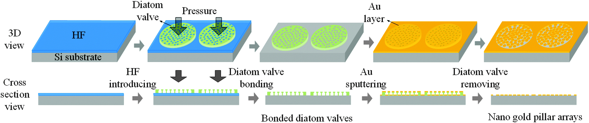 | ||
| Fig. 1 The schematic of the bonding process and the nanogold pillar array acquisition. | ||
Characterization of bonded diatom frustules
SEM and EDS were used to analyze the bonding quality and mechanism, while AFM was used to indirectly measure the bonding strength.30 Bonding conditions like HF concentrations and applied pressures were well investigated. The physical and chemical properties of the diatom shells before and after the bonding process were analyzed using photoluminescence (PL) and infrared spectra scans. The bonding mechanism was discussed while the cross-section of the diatom based Si substrate was analyzed. The bonding strength was obtained with AFM calibrated glass needles, during which a bonded diatom was pushed with the glass needle and the deflection of the needle determined the shearing force.Application of bonded diatom frustules
The diatom frustules could also be used as masks to acquire nano gold pillar arrays. The schematic process is shown in Fig. 1. After diatom frustules were bonded with Si substrates, gold was vertically sputtered on their surface with Cr as an adhesive interlayer. A gold layer was formed inside and outside the diatom nanopores. Later, the diatom based substrate was immersed into HF solution with 40% concentration for 5 min. HF would fully react with the diatom frustules, leaving nano gold pillar arrays on Si substrates. In this section, another kind of Coscinodiscus sp. diatoms (Diameter 100 μm, from the Diatom laboratory, Xiamen University, China) were used, because the Coscinodiscus sp. diatoms had more dedicated structures compared with the Coscinodiscus decrescens. diatoms.After the nano gold pillar arrays were acquired, the SERS activity was demonstrated by modifying the gold arrays with an ethanol solution of crystal violet, whereby crystal violet was used as a probe molecule that could be adsorbed onto the nanoparticle surface as a monolayer. It was left to dry naturally in air. Then, the substrate was immersed into a 1 × 10⁻² mol L−1 crystal violet ethanol solution overnight. After thoroughly rinsing with absolute ethanol several times to remove the free crystal violet molecules, the samples were then subjected to Raman characterization (LabRAM HR800, excitation wavelength 647 nm, magnification ×50). For comparison, the normal Raman spectra of solid crystal violet samples were also measured.
Results and discussion
Bonding quality evaluation
 | ||
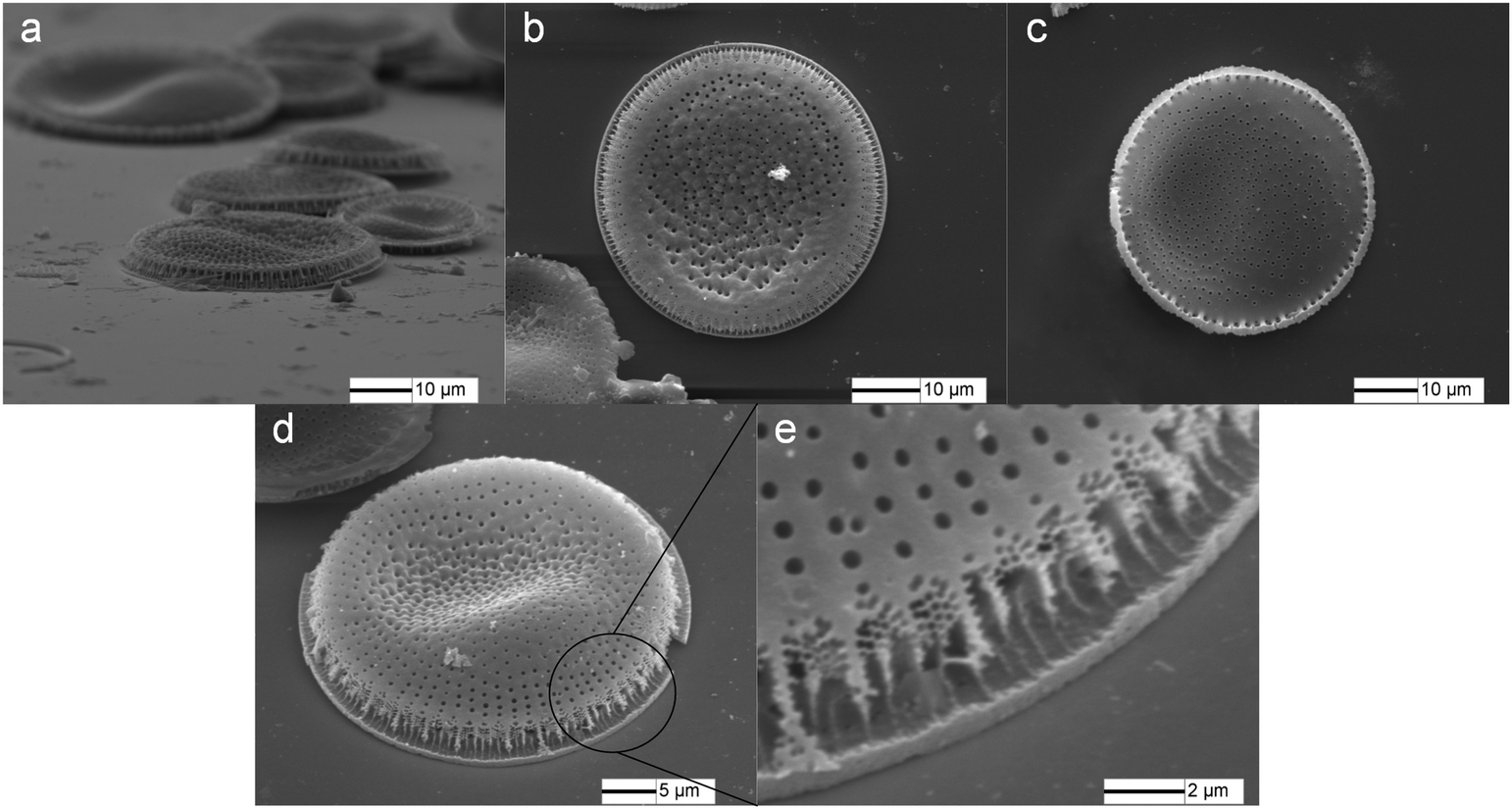
| Fig. 2 The morphology of (a) original Coscinodiscus diatom valves lying on the edge of a glass substrate, (b) the outside view and (c) the inside view of a diatom valve. | ||
 | ||
| Fig. 3 Bonded Coscinodiscus diatom frustules, (a) the bonded diatom frustules, (b) the outside view and (c) the inside view of a diatom, (d) and (e) the bonding area of a diatom and the substrate. | ||
Based on statistical experiments, the outside of a valve had the same opportunity to face upwards or downwards. The valve shaped like a plate, and the morphology of the inside and outside of valves was similar. The direction of valves did not remarkably influence the bonding result. Nevertheless, further study about directions controlling is still being undertaken based on the floating effect of diatoms.31
:H2O2, the surfaces of diatom frustules and Si substrates were both functionalised with the Si–OH group. The Si substrate and diatom frustules were brought into close contact with each other, and a thin HF solution layer was between them and reaction took place. During the bonding process, Si–OH groups gradually dehydrated with the help of HF, forming siloxane bonds and terminating with a condensation–polymerization reaction (Fig. 4).25,32
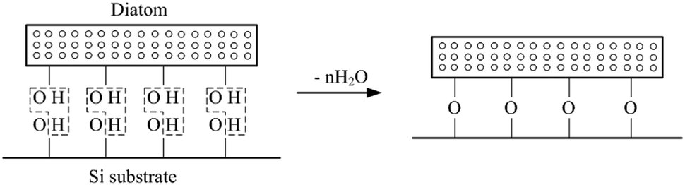 | ||
| Fig. 4 The dehydration and condensation/polymerization of Si–OH groups during bonding. | ||
In addition, as diatom frustules were all made of SiO2, HF would react with diatom frustules as follows.
| SiO2 + 4HF = SiF4↑ + 2H2O |
In order to further analyze the bonding quality and mechanism, the cross-section of the diatom based Si substrate was acquired. The Si substrate bonded with diatom frustules (HF concentration 0.5%, applied pressure 2.5 × 10⁴ Pa) was cut with glass cutter. The cutting force was exerted on the back of the substrate, and the diatom based substrate broke into two halves. With the cutting track through the center of a single diatom, the diatom broke off into two halves together with the substrate (Fig. 5a). The contacting area between diatom frustules and the Si substrate unified as a whole (Fig. 5b), while the nanopores and the cavum structures inside the diatom frustules remained undestroyed. In addition, EDS was used to analyze the bonding area. Table 1 shows the chemical composition of the star-marked area in Fig. 5c. Despite the systematic error of the spectrum analyzer, the bonding area was the combination of Si and SiO2, which means that the bottom of diatom frustules actually dissolved and then unified with the Si substrate as a whole. It seemed that there was a flat intermediate layer between the diatom frustule and the substrate. This might be caused by the edge crushing when the diatom based substrate was cut into two half.
 | ||
| Fig. 5 The cross-sectional view of a bonded diatom, (a) schematic image of the cross-section, (b) the cross-sectional image of the bonded Coscinodiscus diatom, and (c) the bonding interface and marked area for EDS. | ||
| Area | 1 | 2 | 3 |
|---|---|---|---|
| Si (%) | 34.02 | 61.98 | 99.71 |
| O (%) | 65.98 | 38.02 | 0.29 |
Later, the PL and infrared spectra scan experiments were carried out, indicating that there were merely any physical or chemical property changes of the valve before and after bonding. As a result, the surface of the valve could still be modified for photoluminescence and electrochemical detection in bio-chemical sensors.
Optimization of bonding conditions
As mentioned in our previous work,17 the glass needle and AFM could be used to precisely quantify the bonding strength. Firstly, a bonded diatom (0.5% HF concentration, 2.5 × 10⁴ Pa applied pressure) was pushed with the calibrated glass needle and the needle was deflected (Fig. 6a and b). When the glass needle deflected to a certain degree, the diatom crushed (Fig. 6c). The main structure of the diatom was broken and removed by the glass needle. But some remaining pieces of diatom frustules were still firmly bonded to the substrate (Fig. 6c), indicating that the bonding force was equal or even higher than the shearing force provided by the glass needle. In addition, the morphology of bonding areas was different from that of other areas, indicating that certain chemical reactions happened during the bonding process.
 | ||
| Fig. 6 Bonding strength acquisition, (a) and (b), a bonded diatom is pushed with the calibrated glass needles, (c) the crushed diatom. | ||
The spring constant of our glass needle was 0.944 N m−1. Fig. 6 shows the bonding result with a HF concentration of 0.5% and an applied pressure of 2.5 × 10⁴ Pa. With 900 μm deflection, the needle has resisted an applied force of 850 μN, which is also the bonding force between one diatom and the substrate. Mostly the valve is not completely flat and only about 60% of its surface can directly come into contact with the Si substrate. For this reason, the contact area of one diatom and the substrate can be taken as nearly 1178 μm.2 As a result, the bonding strength of diatom frustules and the substrate is approximately 0.72 MPa.
The bonding process took at least 24 hours at room temperature. In order to improve the bonding efficiency, all the bonding experiments were employed with a constant temperature of 75 °C for 2 hours. Since the applied pressure and the concentration of the HF solution were two most crucial factors affecting the bonding strength and the morphological integrity of the diatom, discussions about these two factors were done and the bonding strength was measured using glass needles respectively and shown in Fig. 7.
 | ||
| Fig. 7 The bonding strength variation with applied pressure and HF concentration. | ||
The HF concentration was one important factor affecting the bonding strength. As shown in Fig. 7, when the HF concentration was lower than 0.4%, the diatom frustules could not be fully reacted with Si substrates and the bonding strength was relatively low. With the increase of the HF concentration, the bonding strength increased. When the HF concentration reached 0.5%, the highest bonding strength was obtained. However, if the HF concentration kept on increasing, diatom frustules fully reacted with HF and the main structure and nanopores of diatom frustules were severely damaged. Therefore, the bonding strength fell with the increase of HF concentration when the HF concentration was higher than 0.5%. Finally, the optimized HF concentration should be between 0.4% and 0.6% to achieve enough bonding strength while preserving the morphological integrity of diatom frustules.
In addition, the applied pressure was another crucial factor for the bonding strength. The bonding strength of diatom frustules and Si substrate was relatively low when the applied pressure during bonding was below 2.0 × 10⁴ Pa. With the increase of the applied pressure, the bonding strength increased. When the pressure reached 2.5 × 10⁴ Pa, we got the highest bonding strength. Afterwards the bonding strength fell with the increase of the applied pressure because more diatom valves crushed into pieces under such high pressure. Finally, the optimized pressure was found to be in the range of 2.0 × 10⁴ Pa to 3.0 × 10⁴ Pa with consideration of the balance of the bonding strength and damage to diatom frustules.
Applications of bonded diatom frustules
As the diatom frustules still had nanoscale through pores regularly laid on the valves, they could be used as masks to acquire nano gold pillar arrays, which might have an SERS effect. Coscinodiscus sp. diatoms were also used in this part. And these pores showed a radicalized distribution pattern. Fig. 8a shows the top view of one Coscinodiscus sp. diatom frustule. The hierarchical microscale/nanoscale pores of diatom were radially distributed from the center of the frustule. For the nanoscale pores (diameter 80 nm), seven of them would form a heptamer structure (Fig. 8b).
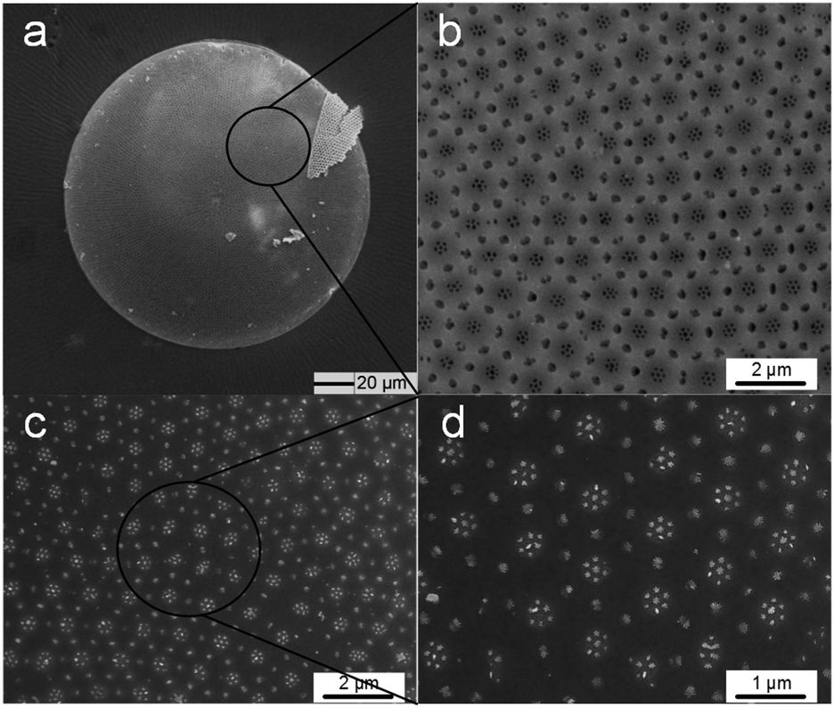 | ||
| Fig. 8 The nano gold pillar array, (a) the nano gold pillar array acquired with Coscinodiscus, the surface morphology of a Coscinodiscus sp. valve (b) before and (c) after it is sputtered with gold, (d) the nano gold pillar array acquired based on it. | ||
The bonding process was gentle in this part (0.3% HF concentration, 1.5 × 10⁴ Pa applied pressure), because serious reaction would destroy the nanopore structures of Coscinodiscus sp. diatom frustules. And the sputtering in this part did not require high bonding strength.
After gold was sputtered, HF was used to remove the diatom frustules. Nano gold pillar arrays were acquired (Fig. 8c). The nano gold pillar had the same size as the nano pore. Seven nano gold pillars formed a symmetrical heptamer cluster, whose diameter was around 400 nm (Fig. 8d). This kind of heptamer structure has many applications in the SERS field.
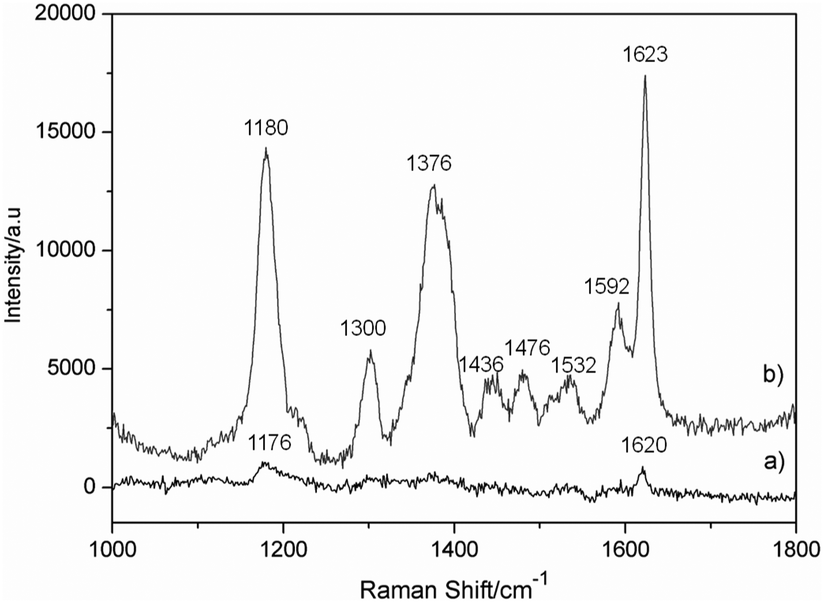 | ||
| Fig. 9 (a) Raman spectrum of crystal violet, (b) SERS spectrum of crystal violet on diatom frustules. | ||
To evaluate the magnitude of the enhancement factor (EF) for crystal violet on nano gold pillar arrays, the following equation was used.34
 290, Ibulk = 1082) at 1179 cm−1, the EF was estimated to be around 7.64 × 10⁴.
As there were thousands of diatoms species with thousands of different nano pores distributions, various nano gold pillar arrays could be acquired for different applications. This technique will be further discussed in the following research paper.
Conclusions
In summary, Coscinodiscus diatom frustules were bonded with Si substrates using a low temperature HF assisted bonding method. SEM and EDS were used to analyze the bonding area and bonding mechanism. The physical and chemical properties of diatom frustules almost remained unchanged after bonding. In order to achieve sufficient bonding strength while keeping the morphological integrity of the bonded diatom frustules, bonding conditions were optimized. The optimized pressure was between 2.0 × 10⁴ Pa and 3.0 × 10⁴ Pa, and the optimized concentration of HF is from 0.4% to 0.6%. The optimal shear bonding strength between Coscinodiscus decrescens. diatom frustules and Si substrates was around 0.72 MPa. The diatom based substrates may be used for improved photoluminescence and electrochemical detection in the bio-chemical sensor field in the future. And bonded diatom frustules were also used as masks to obtain nano gold pillar arrays having an SERS effect. This technique should be also useful for bonding of other micro silica particles with Si substrates, which will greatly contribute to the diatoms application in micro-nanotechnology.Acknowledgements
The authors would like to thank Zhang Juan for lots of useful discussion. This work was supported by the National Natural Science Foundation of China (Grant No. 51075020, 51205012 and 51322503)Notes and references
- W. R. Yang, P. J. Lopez and G. Rosengarten, Analyst, 2011, 136, 42–53 RSC.
- R. Gordon, D. Losic, M. A. Tiffany, S. S. Nagy and F. A. S. Sterrenburg, Trends Biotechnol., 2009, 27, 116–127 CrossRef CAS PubMed.
- J. Parkinson and R. Gordon, Trends Biotechnol., 1999, 17, 190–196 CrossRef CAS.
- P. J. Lopez, J. Descles, A. E. Allen and C. Bowler, Curr. Opin. Biotechnol., 2005, 16, 180–186 CrossRef CAS PubMed.
- H. E. Townley, A. R. Parker and H. White-Cooper, Adv. Funct. Mater., 2008, 18, 369–374 CrossRef CAS.
- L. De Stefano, L. Rotiroti, M. De Stefano, A. Lamberti, S. Lettieri, A. Setaro and P. Maddalena, Biosens. Bioelectron., 2009, 24, 1580–1584 CrossRef CAS PubMed.
- D. K. Gale, T. Gutu, J. Jiao, C. H. Chang and G. L. Rorrer, Adv. Funct. Mater., 2009, 19, 926–933 CrossRef CAS.
- A. Bismuto, A. Setaro, P. Maddalena, L. De Stefano and M. De Stefano, Sens. Actuators, B, 2008, 130, 396–399 CrossRef CAS PubMed.
- K. C. Lin, V. Kunduru, M. Bothara, K. Rege, S. Prasad and B. L. Ramakrishna, Biosens. Bioelectron., 2010, 25, 2336–2342 CrossRef CAS PubMed.
- S. Lettieri, A. Setaro, L. De Stefano, M. De Stefano and P. Maddalena, Adv. Funct. Mater., 2008, 18, 1257–1264 CrossRef CAS.
- M. De Stefano and L. De Stefano, Phycologia, 2009, 48, 70 CrossRef PubMed.
- D. Losic, J. G. Mitchell, R. Lal and N. H. Voelcker, Adv. Funct. Mater., 2007, 17, 2439–2446 CrossRef CAS.
- D. Losic, J. G. Mitchell and N. H. Voelcker, Chem. Commun., 2005, 4905–4907 RSC.
- J. E. N. Dolatabadi and M. de la Guardia, TrAC, Trends Anal. Chem., 2011, 30, 1538–1548 CrossRef CAS PubMed.
- D. Losic, Y. Yu, M. S. Aw, S. Simovic, B. Thierry and J. Addai-Mensah, Chem. Commun., 2010, 46, 6323–6325 RSC.
- C. Jeffryes, T. Gutu, J. Jiao and G. L. Rorrer, ACS Nano, 2008, 2, 2103–2112 CrossRef CAS PubMed.
- D. Y. Zhang, J. F. Pan, J. Cai, Y. Wang, Y. G. Jiang and X. G. Jiang, J. Micromech. Microeng., 2012, 22, 035021 CrossRef.
- W. Wang, T. Gutu, D. K. Gale, J. Jiao, G. L. Rorrer and C. H. Chang, J. Am. Chem. Soc., 2009, 131, 4178–4179 CrossRef CAS PubMed.
- J. Pan, J. Cai, D. Zhang, Y. Wang and Y. Jiang, Physica E, 2012, 44, 1585–1591 CrossRef CAS PubMed.
- F. H. Scholes, T. J. Davis, K. C. Vernon, D. Lau, S. A. Furman and A. M. Glenn, J. Raman Spectrosc., 2012, 43, 196–201 CrossRef CAS.
- H. Takagi, R. Maeda, T. R. Chung and T. Suga, Sens. Actuators, A, 1998, 70, 164–170 CrossRef CAS.
- H. Seki, T. Ono, Y. Kawai and M. Esashi, J. Micromech. Microeng., 2008, 18, 085003 CrossRef.
- P. Yu, C. Pan and J. Xue, Mater. Lett., 2005, 59, 2492–2495 CrossRef CAS PubMed.
- W. H. Teh, A. Trigg, C. H. Tung, R. Kumar, N. Balasubramanian and D. L. Kwong, Appl. Phys. Lett., 2005, 87, 073107 CrossRef.
- H. Nakanishi, T. Nishimoto, R. Nakamura, A. Yotsumoto, T. Yoshida and S. Shoji, Sens. Actuators, A, 2000, 79, 237–244 CrossRef CAS.
- H. Nakanishi, T. Nishimoto, M. Kanai, T. Saitoh, R. Nakamura, T. Yoshida and S. Shoji, Sens. Actuators, A, 2000, 83, 136–141 CrossRef CAS.
- D. Losic, J. G. Mitchell and N. H. Voelcker, New J. Chem., 2006, 30, 908–914 RSC.
- Y. Gan, Rev. Sci. Instrum., 2007, 78, 081101 CrossRef PubMed.
- D. Y. Zhang, Y. Wang, J. F. Pan and J. Cai, J. Mater. Sci., 2010, 45, 5736–5741 CrossRef CAS.
- C. E. Hamm, R. Merkel, O. Springer, P. Jurkojc, C. Maier, K. Prechtel and V. Smetacek, Nature, 2003, 421, 841–843 CrossRef CAS PubMed.
- Y. Wang, J. F. Pan, J. Cai and D. Y. Zhang, Biochem. Biophys. Res. Commun., 2012, 420, 1–5 CrossRef CAS PubMed.
- L. X. Chen, G. A. Luo, K. H. Liu, J. P. Ma, B. Yao, Y. C. Yan and Y. M. Wang, Sens. Actuators, B, 2006, 119, 335–344 CrossRef CAS PubMed.
- Y. Wang, D. Zhang, J. Pan and J. Cai, J. Mater. Sci., 2012, 47, 6315–6325 CrossRef CAS.
- L. Jiang, P. Yin, T. You, H. Wang, X. Lang, L. Guo and S. Yang, ChemPhysChem, 2012, 13, 3932–3936 CrossRef CAS PubMed.
| This journal is © The Royal Society of Chemistry and the Centre National de la Recherche Scientifique 2014 |