DOI:
10.1039/C3NJ00776F
(Paper)
New J. Chem., 2014,
38, 84-89
Fabrication of flower-like ZnO nanosheet and nanorod-assembled hierarchical structures and their enhanced performance in gas sensors
Received
(in Montpellier, France)
14th July 2013
, Accepted 1st October 2013
First published on 2nd October 2013
Abstract
Nanosheet-assembled hierarchical flower-like ZnO nanostructures formed from closely packed nanosheets have been fabricated from an ethanol-assisted hydrothermal route at a temperature of 140 °C. It was found that the solvent played a key role in the formation process of the hierarchical ZnO nanostructures in this reaction system. Most importantly, the as-prepared nanosheet-assembled flower-like ZnO (S-1) nanostructures exhibited excellent sensing properties towards acetone, up to 35.1 within 0.5 s towards 500 ppm acetone, which were much better than those of nanorod-assembled flower ZnO nanostructures (S-2) and ZnO microspheres (S-3). A detailed investigation revealed that a large number of almost invisible pores existed in the ZnO superstructures, which play a key role in the transport pathways of small molecules, resulting in nanosheets with a high level of sensing activity.
1. Introduction
ZnO is of interest in many applications including gas sensors, photonic devices, energy conversion/storage, catalysis and solar cell materials.1–4 With their appropriate energy gap of 3.37 eV and large exciton bonding energy of 60 MeV,5 ZnO nanomaterials are considered to be valuable sensing materials in the gas sensor field for the detection different gases.6,7 It is well-known that the gas-sensing characteristics of metal oxide semiconductor sensors are generally related to the surface adsorption and desorption of the materials.8 Therefore, the structure and morphology of ZnO are important parameters for ZnO-based gas sensors that possess high response levels and rapid response times.8 In addition, one of the best methods to achieve this is to construct ZnO materials with hierarchical nanostructures.
In recent years, hierarchical micro- and nanoscale structures have attracted great interest due to their structures and impressive physicochemical properties such as, for example, their less agglomerated configurations and high surface areas, which differ from their solid counterparts, thus giving them the prospect for potential application in chemical sensors.9 In particular, hierarchical oxide structures as gas sensing materials show good sensing properties due to well-aligned porous structures without scarifying high surface area.10 Thus, research into three-dimensional hierarchical structures, formed using the surfactant-assisted self-assembly of nanoparticles, nanorods, nanotubes, nanosheets, or other composites, has become a hot topic.11 Many methods can be used to produce 3D hierarchical ZnO architectures, for example, specific peptides can catalyze and induce flower-like ZnO nanostructures12 and initial 1D ZnO nanostructures can be assembled form brush-like hierarchical ZnO nanostructures.13 However, developing a facile and effective method for the fabrication of 3D hierarchical architectures remains an enormous challenge.
Herein, we have developed a facile hydrothermal strategy using different solvent-assisted methods combined with a subsequent calcination in order to fabricate 3D hierarchical flower-like ZnO architectures in the form of nanosheets and nanorods. We have investigated the acetone-sensing properties of these hierarchical flower-like ZnO architectures. The gas response of the sheet-like ZnO flower sensor was significantly higher than that of the others. The enhanced sensor properties could be due to the unique nanosheets, which have large surface areas and porous structures that are beneficial for mass transport and gas diffusion throughout the whole sensing material.
2. Experimental
2.1. Synthesis of the materials
The purity of all of the chemicals used was analytical grade. In addition, no subsequent purification processes were carried out. In the experiments, 0.245 g Zn(CH3COO)2 was added to a mixture of 15 mL deionized water and 10 mL absolute ethanol with vigorous stirring at room temperature. 0.4 g glycine and 0.4 g sodium sulfate (Na2SO4) were added and the mixture was then stirred for 5 min. Afterwards, 10 mL NaOH solution (1 M) was added to the above solution, which was then stirred for 1 h. The resulting white suspension was loaded into a 40 mL Teflon-lined autoclave. The autoclave was sealed tightly and then heated at 140 °C for 18 h, before subsequently being cooled to room temperature. A white colored product was obtained by centrifugation with ethanol and deionized water. After drying at 60 °C for 24 h, the as-synthesized ZnO sample was annealed at 500 °C for 2 h using a temperature gradient of 5 °C min−1. Two other types of ZnO samples were prepared for comparison purposes using a similar method. Details of the synthesis conditions for the other ZnO nanostructures are shown in Table 1.
Table 1 Detailed experimental conditions for the preparation of the samples
| Sample no. |
Starting reagents |
Temperature and time |
Morphology |
| S-1 |
0.245 g Zn(Ac)2 + 15 mL H2O + 10 mL C2H5OH + 0.4 g glycine + 0.4 g Na2SO4 + 10 mL NaOH |
140 °C, 8 h |
Sheet-like flowers |
| S-2 |
0.245 g Zn(Ac)2 + 25 mL H2O + 0.4 g glycine + 0.4 g Na2SO4 + 10 mL NaOH |
140 °C, 8 h |
Rod-like flowers |
| S-3 |
0.245 g Zn(Ac)2 + 25 mL glycol + 0.4 g glycine + 0.4 g Na2SO4 + 10 mL NaOH |
140 °C, 8 h |
Sheet-like spheres |
2.2. Characterization
The sizes and structures of the as-synthesized ZnO samples were determined using X-ray diffraction (XRD, λ = 0.15418 nm, D/Max-2550, 40 kV, 350 mA), field emission scanning electron microscopy (FESEM, SHIMADZU Japan, SSX-550), transmission electron microscopy (TEM) with selected area electron diffraction (SAED) and energy-dispersive X-ray (EDX) microanalysis, and high resolution transmission electron microscopy (HRTEM: Japan RILI H-8100).
2.3. Fabrication and measurements of the gas sensors
The gas sensors with sensing and heating elements were fabricated using a coating method. A more detailed preparation process is described in our previous work.14 Briefly, a sensing paste composed of a ZnO product and deionized water (weight ratio of 4![[thin space (1/6-em)]](https://www.rsc.org/images/entities/char_2009.gif) :1) was successively deposited onto a ceramic tube with two gold electrodes. A Ni–Cr heating wire was placed inside the ceramic tube to be used as a resistor for adjusting the overall temperature of the sensor. Fig. 1 shows the structure of the sensor.14
:1) was successively deposited onto a ceramic tube with two gold electrodes. A Ni–Cr heating wire was placed inside the ceramic tube to be used as a resistor for adjusting the overall temperature of the sensor. Fig. 1 shows the structure of the sensor.14
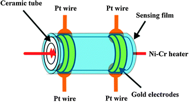 |
| | Fig. 1 Schematic showing the structure of the gas sensor.14 | |
The gas-sensing characteristics of the ZnO nanomaterials were measured using an (RQ-2) Intelligent Test Meter. The response of a sensor is defined as the ratio (S = Ra/Rg for the reduced gas or S = Rg/Ra for the oxidised gas) of the sensor resistance in dry air (Ra) to that in the testing gas (Rg). The response and recovery times are defined as follows: the response time is the time taken from Ra to Ra − 90% (Ra – Rg) and the recovery time is the time taken from Rg to Rg + 90% (Ra – Rg).
3. Results and discussion
3.1. Structural and morphological characteristics
Fig. 2(a–c) shows the XRD patterns of the three ZnO nanomaterials obtained after the calcination process. All of the diffraction patterns show the peaks characteristic to ZnO with a wurtzite structure (JCPDS No. 36-1451) and lattice constants of a = 3.249 and c = 5.206. Moreover, the intensity of the diffraction peaks of the three ZnO nanomaterials are much stronger, indicating that the resulting ZnO samples were of higher crystallinity. No other diffraction peaks related to impurities are observed, indicating the formation of pure wurtzite ZnO.
 |
| | Fig. 2 XRD spectra of the as-prepared hierarchical ZnO structures: (a) S-1, (b) S-2, and (c) S-3. | |
The morphology and microstructure of the three ZnO nanostructures (synthesised using different solvent-assisted hydrothermal methods) were determined using FESEM. Fig. 3(a and b) indicate that the S-1 sample consists of flower-like nanostructures with diameters of about 4.5 μm. In addition, S-1 exhibited a well-formed structure without any aggregation and uniformity across the substrate. A magnified FESEM image (Fig. 3(c)) showed that the S-1 product consisted of hierarchical flower-like nanostructures assembled from nanosheet building blocks with thicknesses of about 40 nm.
 |
| | Fig. 3 FESEM images of the as-synthesized hierarchical ZnO structures: (a–c) S-1 sample; (d–f) S-2 sample; (g–i) S-3 sample. | |
Fig. 3(d and e) indicate that the S-2 sample is composed of homogeneously sized nanostructures with tapered branches. In addition, each nanostructure consists of many tightly aggregated nanorods. From the single S-2 structure shown in Fig. 3f, the rod-assembled structure and rough surface can be clearly discerned. The diameter of the rods is in the range of 100–200 nm (Fig. 3(f)). When using the glycol-assisted method (Fig. 3(g and h)), it is clear that the product mainly consists of a large quantity of microspheres with average diameters of about 4–6 μm. In order to investigate the surface structures, a high magnification FESEM image was taken, which shows that the S-3 microspheres have rough surfaces, and are aggregates of numerous ZnO nanorods with diameters of about 70 nm (Fig. 3(i)).
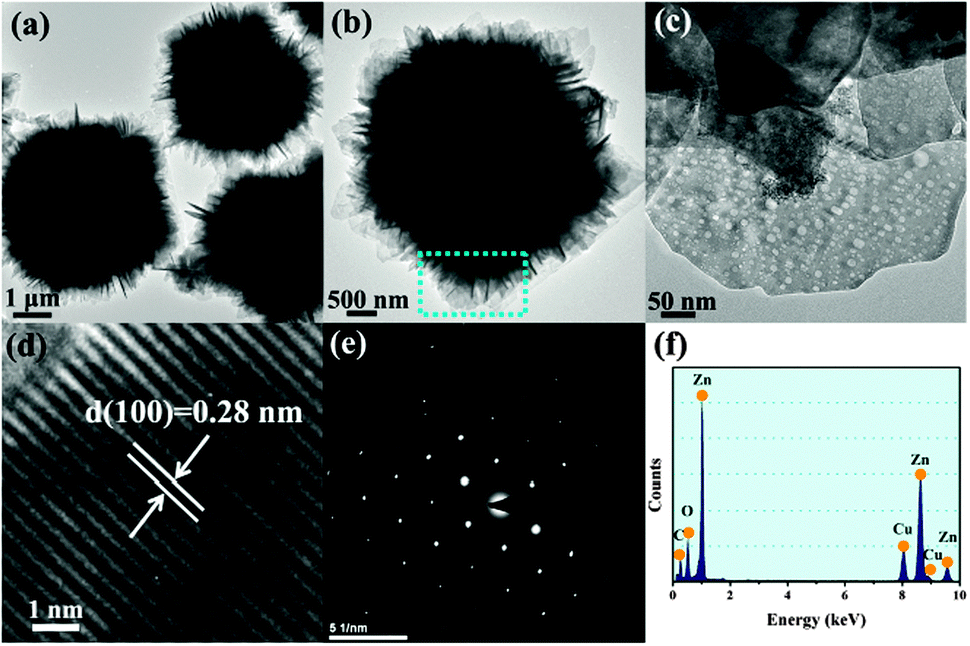
In order to further research the morphology of the sheet-like ZnO flowers, typical TEM and HRTEM images were collected, as shown in Fig. 4. Fig. 4(a and b) show typical TEM images of the ZnO hierarchical structures with a flower-like shape. Measurements show that the S-1 structures have diameters in the range of about 4.5 μm, which are in good agreement with those shown in Fig. 3(b). In Fig. 4(c) a part of a nanosheet has been further magnified to show its flower-like nanostructure, nearly hollow cavities and porous wall. This porous network can offer a large number of channels for the test gases to effectively diffuse into the interior of the material, thus generating two electron depleted layers on both surfaces of the nanosheets, resulting in an enhancement of the sensing performance.15 It is worth noting that the sheet-like flower structures are extremely stable and cannot be damaged, even after ultrasonication over a long period of time. A representative HRTEM image of a small part of the ZnO nanosheet is shown in Fig. 4(d), from which the (110) lattice spacing (0.28 nm) of the hexagonal ZnO can be clearly determined. Both the HRTEM image and the corresponding SAED pattern (which exhibits many separate spots) of the nanosheet confirm that the sheet-like ZnO flower structures are a single-crystal structure (Fig. 4(e)). The composition of the as-synthesized ZnO was determined from the EDX spectrum (Fig. 4(f)). The spectrum indicates that the as-synthesized ZnO are mostly composed of Zn and O species. The signals for Cu and C mainly arise from the copper grid and carbon film used.
 |
| | Fig. 4 (a) and (b) TEM images of a typical S-1 sample; (b) an enlarged image of the connecting area labeled by the rectangle in (b); (c) HRTEM image of a ZnO nanosheet; (d) the corresponding SAED pattern; (f) the EDX spectrum of the as-prepared S-1 structures. | |
3.2. Acetone sensing properties
The effect of the working temperature on the semiconductor oxide sensors, which is an important functional characteristic, was investigated first. Fig. 5 shows the response curves of S-1, S-2 and S-3 toward 500 ppm acetone vapor at different working temperatures. In Fig. 5, as the temperature is increased, the responses of the three sensors increase, reaching a maximum at 320 °C, before decreasing rapidly. It is obvious that the highest response towards 500 ppm acetone for the three sensors were 35.1, 24.6 and 20.1 for S-1, S-2 and S-3, respectively. Moreover, it can be observed that the S-2 and S-3 sensors exhibited lower responses due to serious aggregation of the ZnO nanorods/sheets (Fig. 3(f and i)), leading to a decrease in the sensor properties. A parallel mechanism has been previously indicated to be responsible for the improved sensing performance towards NO2.16 On the basis of these results, a temperature of 320 °C was chosen for the subsequent studies.
 |
| | Fig. 5 Response curves of the three ZnO sensors exposed to 500 ppm acetone under different operating temperatures. | |
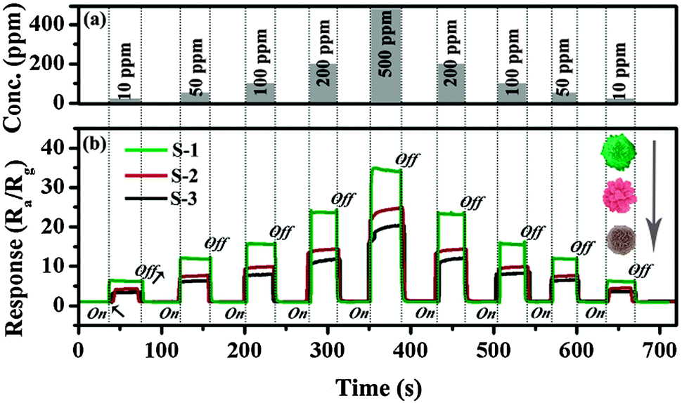
The acetone responses of the three sensors over time are shown in Fig. 6. It can be observed that the S-1 sensor demonstrates a considerable response to acetone. When exposed to 10 ppm acetone, the response value is about 6.5. As the acetone concentration increases from 50 to 500 ppm (Fig. 6(a)), the response values increase to about 12.3, 15.7, 23.7 and 35.2. The response/recovery rates of the three sensors are very fast and change slightly with the increasing acetone concentration. The gas response of S-1 sensor to 100 ppm acetone (Ra/Rg: 15.7) was 1.6-fold and 2.1-fold higher than those of S-2 (Ra/Rg: 9.7) and S-3 (Ra/Rg: 7.6), respectively. Interestingly, Fig. 6(b) also shows that the response of the sensor (cycle 2) could be repeated without a noticeable decrease.
 |
| | Fig. 6 (a) The acetone gas concentration range from 10 to 500 ppm. (b) The hierarchical ZnO gas sensors tested in response to acetone gas at 320 °C, and the reproducibility of the ZnO sensors. | |
The variation in the response as a function of the acetone concentration at 320 °C was non-linear for all of the sensors (Fig. 7). As the acetone concentration increased, the responses of the three sensors also increased. Once the acetone concentration was above 2000 ppm, the sensors became more or less saturated, as shown by the responses increasing more slowly. Finally, at about 5000 ppm the sensors reached saturation. Moreover, the acetone responses for all of the sensors were linear between 10 and 200 ppm (Fig. 7, inset). This indicates that the hierarchical ZnO products are more beneficial for the exploration of low concentrations of acetone.
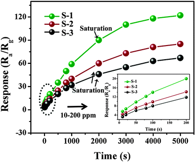 |
| | Fig. 7 Responses of the three sensors to different concentrations of acetone at an operating temperature of 320 °C. The inset shows the linear dependence of the sensitivity on the acetone concentration in the range 10–200 ppm. | |
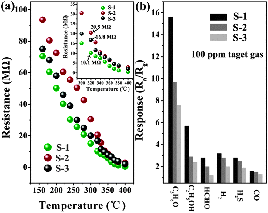
Fig. 8(a) shows the relationship between the sensor resistance in air and the operating temperature. It can be observed that the resistance of all sensors dramatically decreases with increasing temperature. This is a typical characteristic of semiconductor sensors. It can be observed in the inset of Fig. 8(a) that the resistance in air (Ra) of S-1, S-2, and S-3 at 320 °C are 10.1, 20.5, and 16.8 MΩ, respectively. In order to understand the role of the material structures and demonstrate the potential use of S-1 in highly sensitive and selective gas sensors, we measured the gas responses (C3H6O, C2H5OH, HCHO, H2, H2S and CO) of sensor prototypes comprised of three different networks of S-1, S-2, and S-3 at 320 °C, as shown in Fig. 8(b). Compared with the S-2 and S-3 sensors, the response of S-1 to acetone was the highest. Moreover, the responses of S-1 to 100 ppm of the other gases were less than 5, indicating that the sheet-like ZnO flowers may be promising sensitive materials for acetone detection. In particular, the responses to 100 ppm C2H5OH, HCHO, H2, H2S and CO were negligible.
 |
| | Fig. 8 (a) The relationship between the resistance in air and the working temperature of the three sensors. The inset shows an enlargement of the relationship at working temperatures in the range 300–400 °C. (b) Response of the three sensors to 100 ppm of various gases at 320 °C. | |
The response and recovery characteristics of the sensor are also important factors for determining the properties of gas sensors. In order to study the response and recovery features of the S-1 sensor, the gas sensor was subsequently exposed to 100 ppm acetone at 320 °C. When exposed to 100 ppm acetone, the response and recovery times were about 0.5 and 4 s, respectively, which are among of the shortest times in the literature (Fig. 9). The response times for acetone in the literature are summarized in Table 2.17–20 The inset of Fig. 9 shows that the response of the sensor could be repeated in three reversible cycles.
 |
| | Fig. 9 Transient response of the S-1 sensor to 100 ppm acetone at 320 °C. The inset shows three response curve cycles. | |
Table 2 Response times of various ZnO sensors towards acetone in the present study and those reported in the literature
| Material |
Size (μm) |
Conc. (ppm) |
Tem. (°C) |
T
Res (s) |
| Conc. (ppm) = concentration, Tem. (°C) = temperature, TRes (s) = response time. |
| This work |
∼4.5 |
100 |
320 |
0.5 |
| ZnO hollow nanofibers17 |
∼0.17 |
100 |
220 |
11–17 |
| ZnO crystallites18 |
∼0.01 |
100 |
300 |
90 |
| ZnO hollow spheres19 |
0.5–1.5 |
100 |
300 |
12 |
| Co-doped ZnO nanofibers |
∼0.08 |
100 |
360 |
6 |
3.3. Gas sensing mechanism of the hierarchical flower-like ZnO
The good performance of the hierarchical flower-like ZnO sheets can be attributed to two factors. Firstly, the structures of the prepared micro sheet/rod-like ZnO are hierarchical structures, which have large surface areas. It is well known that when the particle size becomes comparable to or smaller than the Debye length this can lead to an abrupt increase in the gas response.21,22 However, when the particle size is smaller, the aggregation phenomenon between the nanoparticles becomes very serious due to attractive van der Waals forces, which are inversely proportional to the particle size and decrease the effective surface area.23,24 Hierarchical nanostructures with large surface areas and well-aligned porous structures have been reported.14,25–27 Secondly, the abundant pores that are distributed throughout the nanosheets can improve the diffusion of the target gas and enhance the kinetics of both the reaction of the target gas with negatively charged oxygen and the replacement of the latter from the gas phase.28 When a bulky solid cluster of micro/nano structures are placed under a test gas, the gas has difficulty diffusing throughout the particles, due to a decrease of the effective surface area. Remarkably, the entire surface of the hierarchical nanostructures in our work remains exposed. Moreover, the porous structure of the nanosheets (in Fig. 4c) can also facilitate gas diffusion. Thus, a high response level and fast response and recovery times were obtained.
For n-type semiconductors, the classical model of an electron depletion layer generated by surface oxygen species (O2−, O−, and O2−) is usually considered to be responsible for the sensing mechanism.29 In ambient air, chemisorbed oxygen species are formed due to oxygen molecules capturing free electrons from the surface of the ZnO nanostructures. Therefore, ZnO sensors are in a high resistance state in ambient air.30 When the sensors are placed under acetone gas, the ZnO sample can obtain electrons from the reaction between adsorbed oxygen and acetone, as shown in eqn (1)–(3). Although the carrier-depleted layer of the ZnO sample becomes thinner, the resistance of the ZnO sample is not reduced to any large extent because the carrier-depleted layer is electronically connected in parallel with the rest of the ZnO sample, which remains highly conductive.31
| | | CH3COCH3 + O− → CH3C+O + CH3O− + e− | (1) |
4. Conclusions
In summary, hierarchical ZnO nanostructures with different structures were fabricated using a facile, simple one-pot hydrothermal method. The diameter of the hierarchical flower-like ZnO with nanosheet structures averaged about 4.5 μm, while the thickness of each nanosheet was about 40 nm. The sensor based on the hierarchical flower-like ZnO with nanosheet structures exhibited excellent acetone sensing performance at 320 °C with response and recovery times of 0.5 and 4 s, respectively. The gas response of the flower-like ZnO nanostructures to 100 ppm acetone (Ra/Rg: 11) was 1.6 and 2.1-fold higher than that of the other two structures formed. The above data emphasize the significance of the prepared flower-like ZnO hierarchical structures for application in the monitoring of acetone gas.
Acknowledgements
This research work was financially supported by the Natural Science Foundation Committee (NSFC, Grant No. 609710, 51272158 and 51102109). Shanghai Nano Special Foundation (11nm0502600) and Project of Innovation Research Team of Jilin University (Grant No. 201004003).
Notes and references
- P. X. Gao and Z. L. Wang, J. Am. Chem. Soc., 2003, 125, 11299 CrossRef CAS PubMed.
- X. D. Wang, C. J. Summers and Z. L. Wang, Nano Lett., 2004, 4, 423 CrossRef CAS.
- N. Hongsith, E. Wongrat, T. Kerdcharoen and S. Choopun, Sens. Actuators, B, 2010, 144, 67 CrossRef CAS PubMed.
- D. C. Reynolds, D. C. Look and B. Jogai, Solid State Commun., 1996, 99, 873 CrossRef CAS.
- M. Huang, S. Mao, H. Feick, H. Yan, Y. Wu, H. Kind, E. Weber, R. Russo and P. Yang, Science, 2001, 292, 1897 CrossRef CAS PubMed.
- D. Barreca, D. Bekermann, E. Comini, A. Devi, R. A. Fischer, A. Gasparotto, C. Maccato, G. Sberveglieri and E. Tondello, Sens. Actuators, B, 2010, 149, 1 CrossRef CAS PubMed.
- B. Weintraub, Z. Z. Zhou, Y. H. Li and Y. L. Deng, Nanoscale, 2010, 2, 1573 RSC.
- J. H. Lee, Sens. Actuators, B, 2009, 140, 319 CrossRef CAS PubMed.
- D. Calestania, M. Zhaa, R. Moscaa, A. Zappettinia, M. C. Carottab, V. D. Nataleb and L. Zanottia, Sens. Actuators, B, 2010, 144, 472 CrossRef PubMed.
- Y. Z. Lv, C. R. Li, L. Guo, F. C. Wang, Y. Xu and X. F. Chud, Sens. Actuators, B, 2009, 141, 85 CrossRef CAS PubMed.
- Y. Zeng, T. Zhang, H. T. Fan, W. Y. Fu, G. Y. Lu, Y. M. Sui and H. B. Yang, J. Phys. Chem. C, 2009, 113, 19000 CAS.
- H. Y. Bai, F. Xu, L. Anjua and H. Matsui, Soft Matter, 2009, 5, 966 RSC.
- Y. Zhang, J. Q. Xu, Q. Xiang, H. Li, Q. Y. Pan and P. C. Xu, J. Phys. Chem. C, 2009, 113, 3430 CAS.
- L. L. Wang, H. M. Dou, Z. Lou and T. Zhang, Nanoscale, 2013, 5, 2686 RSC.
- J. Zhang, X. H. Liu, S. H. Wu, M. J. Xu, X. Z. Guo and S. R. Wang, J. Mater. Chem., 2010, 20, 6453 RSC.
- C. Marichy, N. Donato, M. G. Willinger, M. Latino, D. Karpinsky, S. H. Yu, G. Neri and N. Pinna, Adv. Funct. Mater., 2011, 21, 658 CrossRef CAS.
- S. H. Wei, M. H. Zhou and W. P. Du, Sens. Actuators, B, 2011, 160, 753 CrossRef CAS PubMed.
- S. S. Nath, M. Choudhury, D. Chakdar, G. Gope and R. K. Nath, Sens. Actuators, B, 2010, 148, 353 CrossRef CAS PubMed.
- H. M. Zhang, C. Xu, P. K. Sheng, Y. J. Chen, L. Yu and Q. H. Li, Sens. Actuators, B, 2013, 181, 99 CrossRef CAS PubMed.
- L. Liu, S. C. Li, J. Zhuang, L. Y. Wang, J. B. Zhang, H. Y. Li, Z. Liu, Y. Han, X. X. Jiang and P. Zhang, Sens. Actuators, B, 2011, 155, 782 CrossRef CAS PubMed.
- C. N. Xu, J. Tamaki, N. Miura and N. Yamazoe, Sens. Actuators, B, 1991, 3, 147 CrossRef CAS.
- L. L. Wang, Z. Lou, T. Zhang, H. T. Fan and X. J. Xu, Sens. Actuators, B, 2011, 155, 285 CrossRef CAS PubMed.
- B. K. Kim and S. D. Choi, Sens. Actuators, B, 2004, 98, 239 CrossRef PubMed.
- M. Shoyama and N. Hashimoto, Sens. Actuators, B, 2003, 93, 585 CrossRef CAS.
- S. Sun, W. Wang, H. Xu, L. Zhou, M. Shang and L. Zhang, J. Phys. Chem. C, 2008, 112, 17835 CAS.
- K. I. Choi, H. R. Kim and J. H. Lee, Sens. Actuators, B, 2009, 138, 497 CrossRef CAS PubMed.
- Y. Zhang, X. L. He, J. P. Li, H. G. Zhang and X. G. Gao, Sens. Actuators, B, 2007, 128, 293 CrossRef CAS PubMed.
- M. Tiemann, Chem.–Eur. J., 2007, 13, 8376 CrossRef CAS PubMed.
- J. C. Belmonte, J. Manzano, J. Arbiol, A. Cirera, J. Puigcorbe, A. Vila, N. Sabate, I. Gracia, C. Can'e and J. R. Morante, Sens. Actuators, B, 2006, 114, 881 CrossRef CAS PubMed.
- N. J. Dayan, S. R. Sainkar, R. N. Karekar and R. C. Aiyer, Thin Solid Films, 1998, 325, 254 CrossRef CAS.
- K. Arshak and I. Gaidan, Mater. Sci. Eng., B, 2005, 118, 44 CrossRef PubMed.
Footnote |
| † These authors are contributed equally to this work. |
|
| This journal is © The Royal Society of Chemistry and the Centre National de la Recherche Scientifique 2014 |
Click here to see how this site uses Cookies. View our privacy policy here.