SU-8 bonding protocol for the fabrication of microfluidic devices dedicated to FTIR microspectroscopy of live cells†
Elisa
Mitri
*ab,
Giovanni
Birarda
c,
Lisa
Vaccari
d,
Saša
Kenig
e,
Massimo
Tormen
a and
Gianluca
Grenci
af
aCNR-IOM, TASC laboratory, S. S. 14 km 163.5 Basovizza, 34149 Trieste, Italy. E-mail: mitri@iom.cnr.it
bUniversità degli studi di Trieste, Piazzale Europa 1, 34100, Trieste, Italy
cLawrence Berkeley National Laboratory, 1 Cyclotron Rd., Berkeley, CA 94720, USA
dElettra Synchrotron Light Laboratory, S. S. 14 km 163.5, 34149 Basovizza, Trieste, Italy
eStructural Biology Laboratory, Elettra-Sincrotrone Trieste, S. S. 14 km 163.5, 34149 Basovizza, Trieste, Italy
fMechanobiology Institute (MBI), National University of Singapore, T-Lab 5A Engineering Drive 1, Singapore. E-mail: mibgg@nus.edu.sg
First published on 30th September 2013
Abstract
Here we present a new bonding protocol for SU-8 negative tone photoresist that exploits the chemical modifications induced in the resin by exposure to 254 nm (UVC) light. Fourier Transform Infrared microspectroscopy (μ-FTIR) was used to carry out a thorough study on the chemical processes and modifications occurring within the epoxy resin by exposure to 365 nm and 254 nm light. In particular, we established that UVC light promotes the opening of the epoxy rings bypassing the post-exposure bake. The possibility to promote a further activation of the resin, already patterned with standard UV lithography, was exploited to produce closed microfluidic devices. Specifically, we were able to fabricate fluidic chips, characterized by broadband transparency from mid-IR to UV and long term stability in continuous flow conditions. CaF2 was used as substrate, coated by sputtering with a nanometric silicon film, in order to make surface properties of this material more suitable for standard fabrication processes with respect to the original substrate. The fabricated microfluidic chips were used to study by μ-FTIR the biochemical response of live breast cancer MCF-7 cells to osmotic stress and their subsequent lysis induced by the injection of deionized water in the device. μ-FTIR analyses detected fast changes in protein, lipid and nucleic acid content as well as cytosol acidification.
Introduction
SU-8 is a high-contrast, high-sensitivity negative tone photoresist, which exhibits several other attractive properties such as mechanical robustness, good thermal and chemical stability, transparency to visible light above 360 nm and biocompatibility.1 Thanks to these characteristics, SU-8 has become one of the most common structural materials for micro-electro-mechanical systems (MEMS) production. On the contrary, its application to microfluidics, and specifically for the fabrication of bioanalytical devices, was hindered by a few but relevant weaknesses: its hydrophobicity, its tendency to its specific adsorption of bioanalytes and its strong fluorescence in the visible range.2 Modifications of the SU-8 surface chemistry were indeed obtained and exploited to overcome some of the aforementioned problems. Plasma-activation and UV-induced grafting of biomolecules have been shown to be effective in reducing the SU-8 hydrophobicity and to provide a surface chemistry suitable for biological applications.3,4 Nevertheless, the strong fluorescence background of the resin still limits its use as a substrate for bioassays, which commonly employ fluorescence readout. Thus, in most applications, SU-8 could only be used as structural material, once removed from the light pathway. The same approach is required for other detection techniques where polymer layers, although thin, may give a background signal that super-imposes to and possibly hides the one from the sample: this is the case of Fourier Transform Infrared microspectroscopy (μ-FTIR).μ-FTIR detects the vibrational pattern of molecules allowing the label-free characterization of the chemical profile of a biological specimen and its correlation with the sample morphology.5 Due to the low IR photon energy, the sample is preserved from heating and radiation damage6 during the measurements. Although powerful and versatile, due to the strong water absorptions in the infrared spectral region, this technique has been limited until recent years to the study of fixed or dried samples. By using this method, it is possible to retrieve information on the relative content and structural arrangement of the most relevant classes of cellular bio-macromolecules (lipids, carbohydrates, nucleic acids, proteins),7,8 but most of the details related to the dynamic nature of the cellular metabolism are lost. Moreover, recent studies showed that fixation protocols could alter the biochemical content of cells, weakening the reliability of the obtained results.9,10 Therefore, the potential of μ-FTIR as a diagnostic tool would be greatly enhanced by the availability of IR-transparent microfluidic devices, able to sustain cellular viability for long periods of time.
Among the vibrational bands of liquid water, the H2O bending mode at ~1645 cm−1 falls in the same spectral region of the amide I band and partially overlaps with amide II.11 These two bands are characteristic for the peptide bond vibrations, and therefore diagnostic for cellular protein content and folding.12,13 In order to make these bands accessible, the optical path of the IR beam within the aqueous medium has to be kept lower than approximately 10 μm, for avoiding bending water band saturation.14 Attenuated total reflection (ATR) FTIR imaging has been applied for live cell imaging, taking advantage of the limited penetration depth of the evanescent field at the ATR crystal-cell interface, which limits the sampled water layer to a few microns or less.15 By using this approach, the full range of the mid-IR spectrum (4000–900 cm−1) remains usable, since also the stretching modes of liquid water above 3000 cm−1 are not saturated. However, only thin cells can be wholly sampled, such as bacteria biofilms, while most of the eukaryotic cells can not be entirely probed by the IR evanescent wave, limiting the possibility of studying the biochemical changes occurring deep inside the cellular body. Conversely, transflection and transmission geometries allow the sampling of the cells along their entire thickness, but impose to maintain the water layer below ~10 μm. In most of the papers appeared in the literature, demountable liquid chambers have been employed, obtained by separating two IR windows with plastic spacers.16–21 In this configuration, the irreproducibility of the optical path among different experiments and its non-uniformity within the chamber make the compensation of the water contribution by aqueous spectrum subtraction unreliable.22,23
We proposed to use microfabrication for manufacturing both static and dynamic devices with controlled and reproducible spacing between CaF2 optical windows.24,25 In the aforementioned papers, the X-ARP 3100/10 resist (Allresist GmbH, Germany) was used as structural material for defining microfluidic channels on the CaF2 substrate, achieving remarkable design flexibility. Nevertheless, the positive tone of this resist limits its time stability when exposed to slightly alkaline environments and light. Therefore long term experiments require more stable resists. In order to fulfill this task, the major hurdle to overcome is the low surface energy of the CaF2, which determines the poor adhesion of most of the common polymers. Recently, we demonstrated that the deposition of a thin silicon layer on top of IR windows guarantees an improvement of their surface energy with negligible modifications of their optical properties26 (see also ESI†). The modified surface properties of silicon-coated CaF2 (CaF2/Si) with respect to the bare substrate make it more suitable for standardized fabrication strategies, such as the use of common photoresists (e.g. SU-8 or PMMA), and it allows the modulation of both substrate topography and surface chemistry.27 However, the need to preserve the transparency to IR light and the brittleness of CaF2 impose severe constraints on the bonding protocols adopted for producing fluidic devices that enable long term measurements. Indeed, CaF2 is less capable of withstanding mechanical stresses in comparison with other materials. In fact, its Knoop hardness and fracture toughness are ~163 kg mm−2 and ~0.3 MPa m1/2 while those of glass (soda-lime) and silicon are ~500 kg mm−2 and 0.8 MPa m1/2, and ~1100 kg mm−2 and 0.9 MPa m1/2 respectively.28–30 Moreover, the thermal expansion of CaF2 is about six times larger than that of silicon, whereas the thermal conductivity is more than ten times smaller, which means that it suffers larger thermal stresses.
Here, we report on the fabrication of SU-8 based devices made on a CaF2/Si substrate for μ-FTIR of live cells under physiological conditions. In particular, a new and effective bonding strategy has been developed and it is detailed in the paper. It consists in exposing two already patterned SU-8 films to 254 nm (UVC) light, for opening the residual epoxy rings in the resin, and then bringing them into contact. A mild thermo-mechanic process is sufficient to promote the chemical bonding between the two SU-8 layers, leading to a fully closed microfluidic device. The explanation of the sealing mechanism is given by μ-FTIR analysis, which highlights differences in the reticulation of the monomer upon exposure to 254 nm light with respect to 365 nm.
The long term stability of the devices was proven in a 48 h time course experiment by optical microscopy and the materials' biocompatibility was verified by using MTT-test on MCF-7 breast cancer cell line. Lastly, as a key study, we investigated by μ-FTIR the lysis of MCF-7 cells induced by osmotic stress after the injection of deionized (DI) water inside the device.
Experimental
Fabrication and test of the microfluidic device
The starting substrates were IR-grade CaF2 circular windows (Crystran, UK), namely Ø 30 × 1 mm as top cover lid and Ø 30 × 2 mm as bottom substrate. Four holes were drilled with a diamond tool, 0.8 mm diameter, on the cover lid to serve as in- and out-lets for the fluidic circuit. The surface of both windows was covered with a thin layer of Si (~15 nm) by Ar magnetron sputtering (1.2 × 10⁻³ mbar, 600 W DC applied power, 15 s total time). A 40 nm thick layer of Omnicoat (Microchem, Newton, MA, USA) was spin coated onto both the optical windows (4000 rpm for 30 s and baking at 110 °C for 10 min) as a primer for the photoresist. This thin polymeric layer did not affect the CaF2 IR transparency (see ESI†). A 7.5 μm thick SU-8 3005 layer (Microchem, Newton, MA, USA), spin coated at 2500 rpm for 30 s and baked at 95 °C for 4 min, was used to define the microfluidic layout onto the bottom window. UV photolithography was done by exposure to 365 nm wavelength with a dose of 120 mJ cm−2 (Karl-Suss MA25 mask aligner equipped with a Hg arc lamp), followed by a post-bake at 95 °C for 3 min. The lid was prepared using SU-8 2000.5 (Microchem, Newton, MA, USA), spin coated at 3000 rpm and pre-baked at 95 °C for 1 min, resulting in a thickness of 300 nm. The same pattern of the bottom window was transferred by photolithography with a dose of 60 mJ cm−2.The chemical bonding of the device was promoted by exposing the two lithographed windows to 254 nm UV-light for 20 seconds (Reinraum Technik Lanz Flood exposure system equipped with CD-Xe lamp 350 W). The latter were then aligned, brought in contact, pressed at 40 bar and heated to 70 °C using a P/O Weber hydraulic press. After 10 min, the assembly was cooled down to room temperature and finally the pressure was released.
The device layout is shown in Fig. 1b. It is made by an elliptical central chamber (2 mm minor axis, 4 mm major axis) to accommodate cells, which are injected into the device via the central channel (200 μm wide). Two lateral narrower channels (50 μm wide) were introduced in order to maintain a constant flow of fresh physiological medium in the central measurement chamber and to possibly inject chemicals. The lateral channels intersect the inlet through a septum made by a row of 8 μm diameter pillars separated by 3 μm gap (see Fig. 1 c–d). The septum prevents cells from entering the lateral channels, while allowing liquids to flow freely. Two additional wells, disconnected from the fluidic circuit, were defined for allowing spectral background collection in air.
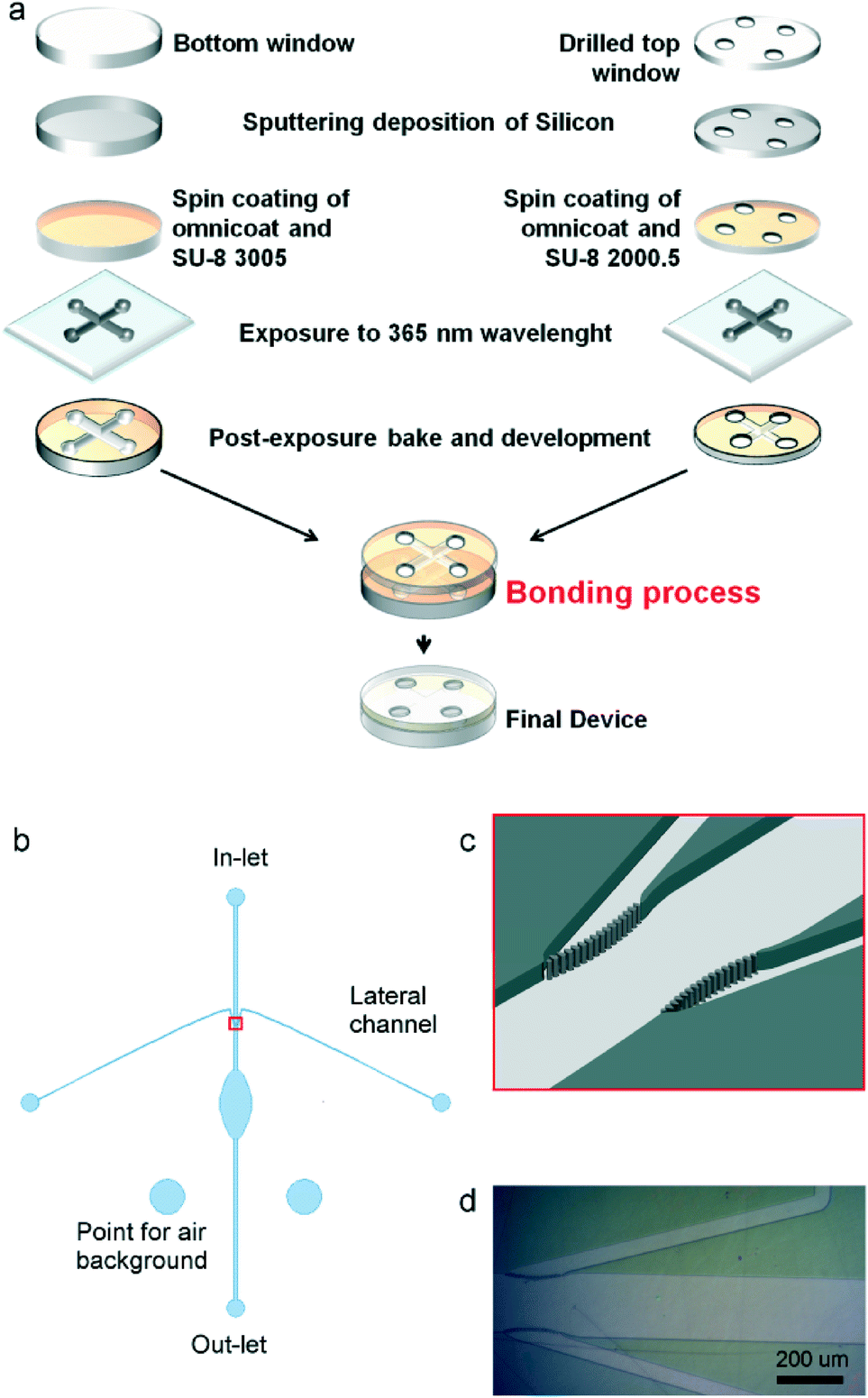 | ||
| Fig. 1 (a) Scheme of the fabrication process (b) layout of the fabricated device: an elliptical inner-chamber is directly connected to an in- and out-let channel 200 μm wide. Two lateral channels (50 μm wide) intersect the inlet before the central chamber. Two additional wells are designed for allowing air background FTIR spectra acquisition (c) scheme of the connection between inlet and lateral channels: the central channel is intercepted by a septum made of 8 μm pillars spaced of 3 μm; (d) optical micrograph of a part of the sealed device fluxed with water. | ||
The fabricated microfluidic chip was enclosed in a plastic holder made by two halves clamped together, which also provided for fluidic connections to the external pumping system (i.e. syringe pumps) through rubber O-rings (see images in ESI†). During all the experiments and tests, this assembly was maintained at 37 ± 0.2 °C with a heating strip controlled with a PT-100 thermocouple. The device bonding was tested by recording images through a CCD camera mounted on a Leica stereo microscope at 10X magnification. During the recording, a flux of 8 μl h−1 of deionized water was maintained for 48 h (see video in ESI†).
FTIR microscopy and imaging of SU-8 films
CaF2/Si substrates were spin-coated with 7.5 μm thick SU-8 3005 films and then exposed as reported in Table 1. FTIR transmission spectra of the different films were acquired at the infrared beamline SISSI (Synchrotron Infrared Source for Spectroscopic and Imaging) at the Elettra Synchrotron Laboratory, Trieste, Italy,31 using a Bruker Hyperion 3000 Vis–IR microscope coupled with Bruker Vertex 70 interferometer. Both interferometer and microscope were purged with nitrogen in order to reduce spectral contributions for environmental water vapour and carbon dioxide. FTIR microspectra of 50 × 50 μm areas of the films were collected in transmission mode with a glow bar source and single point HgCdTe detector, using 15× Schwarzschild condenser and objective, co-adding 256 scans with a spectral resolution of 4 cm−1. Infrared images where acquired using the 64 × 64 pixels Focal Plane Array (FPA) detector co-adding 128 scans with a spectral resolution of 4 cm−1, with a pixel resolution of about 2.56 μm. The acquired raw spectra were corrected for water vapour and CO2 absorption, and baseline corrected using OPUS 6.5 (OPUS NT 6.5, Bruker Optics GmbH, Ettlingen, Germany). Band assignment was done according to peer-reviewed articles.32 Integral areas of the spectral bands characteristic of the resin were calculated using OPUS 6.5.| Conditions | Identifier |
|---|---|
| Not exposed | NE |
| Exposed to 365 nm | 365E |
| Exposed to 365 nm and post-baked | 365E + PB |
| Exposed to 254 nm | 254E |
| Exposed to 365 nm, post-baked and further exposed to 254 nm | 365 + PB + 254E |
Cell preparation and μ-FTIR of live cells
MCF-7 cells (ATCC HTB-22 – breast cancer cell line) were chosen as a model for testing the device. Cells were maintained in Dulbecco's modified Eagle's medium (DMEM), supplemented with fetal bovine serum 10%, in an incubator at 37.0 °C and 5% CO2. Before measurement, cells were harvested from the flask using trypsin, washed twice with fresh physiological solution and finally re-suspended in physiological solution at a concentration of ~1 × 10⁶ cells mL−1. The cell suspension, thermalized at 37 °C, was injected by a syringe pump into the device maintained at the same temperature.After the injection, cells were left to adhere onto the CaF2/Si bottom window for 4 hours. During this time, cells were maintained under a continuous flow of physiological solution of 8 μl h−1, in order to refresh the extracellular medium, and cyclically measured (approximately once per hour). Single cell spectra were collected on thirteen cells, setting knife-edge apertures at 30 × 30 μm, using 15X Schwarzschild condenser and objective, co-adding 256 scans with a spectral resolution of 4 cm−1. The spectrum of a buffer point close to each cell was collected to allow water subtraction. After 4 h, the acquisition was stopped and the medium was replaced by DI water; the data collection was then resumed 10 min later on the same cells, ending only at completion of cell lysis.
The acquired raw spectra were corrected for water vapour, CO2 absorption and baseline using OPUS 6.5. In order to reveal the cellular bands, the buffer spectrum was subtracted to the relative cellular raw spectrum by applying the appropriate scaling factor (0.8 ≤ scaling factor ≤ 1), calculated by running an in-house automated algorithm.9 Band assignment was done according to peer-reviewed papers.33 Area integrals of the spectral bands were calculated using OPUS 6.5. Second derivatives of the spectra were estimated applying Savitzky–Golay algorithm with 13 smoothing points.
MTT assay
MTT assay was used to assess the bio-compatibility of different substrates with respect to MCF-7 cells: bare CaF2, CaF2/Si, CaF2/Si + Omnicoat and CaF2/Si + Omnicoat/SU-8; glass cover slips (Menzel-Glaser, Braunschweig, Germany) and standard plastic multiwell culture plates (Corning) were used as control substrates. Samples were sterilized with 70% ethanol under a laminar flow hood and by exposure to UV light for 3 hours, followed by rinsing in sterile filtered deionized (DI) water for 15 minutes. Cells were plated (6000 cells per window) in a 50 μL drop, left to attach for 30 min and topped up with DMEM medium. After 24 h, MTT reagent (Sigma-Aldrich, St. Louis, MO, USA) was added to a final concentration of 0.5 mg mL−1, and incubated for 3 h. Formazan crystals were dissolved in DMSO and absorbance was measured at 570 nm with Tecan infinite F200 PRO reader. Results are presented as an average of three experiments ± standard deviation.Results and discussion
Biocompatibility of SU-8 devices for bio-MEMS applications
SU-8 resin possesses a combination of interesting properties that can be exploited for the fabrication of bioMEMS for live cell analysis, such as its stability for prolonged exposures under natural light, being a negative tone resist. Regarding the crucial aspect of SU-8 biocompatibility, several papers reported different results, only apparently conflicting.34–37 In fact, they can be reconciled by considering that the biocompatibility of any material, and also of SU-8, is dependent on the cell line, and that other parameters, such as cellular environment, resist formulation, fabrication protocols, and various treatments, may also have an influence on it. Therefore, we focused on the assessment of the biocompatibility of the employed materials and processes for adherent MCF-7 cell line, as it was used for testing our final devices. This breast cancer cell line has been widely used as tumour model since it reflects most of the features of cancer cells in vivo.38The results of the MTT test, shown in Fig. 2, demonstrate that all materials and processes used for the fabrication of the devices exhibit biocompatibility levels comparable to the controls for the MCF-7 cell line. Similar results have been obtained also for U-937 leukemic monocyte cell line, representative of circulating cells.39
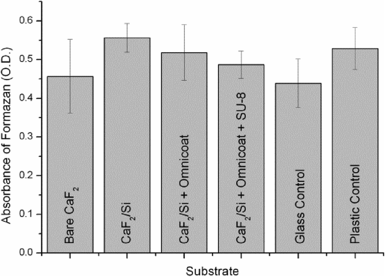 | ||
| Fig. 2 Results of a MTT test represented as absorbance of formazan at 570 nm (optical density, O. D.) for MCF-7 cells cultured onto bare CaF2, CaF2/Si, CaF2/Si + Omnicoat and CaF2/Si + Omnicoat/SU-8 and plastic and glass as controls. Error bars represent ± SD (n = 3) | ||
Furthermore, the silicon interface, directly in contact with the cells, offers the benefit of being easily modifiable via silane chemistry.27 This would allow better tailoring of the surface properties at the device-cell interface in order to improve its compatibility for more sensitive cell lines, such as neurons or primary cultures.
SU-8 bonding protocol
There is extensive documentation about the micro-fabrication of SU-8 based microfluidic chips with different methodologies for the bonding of two or more layers of a device.32,40–43 In the majority of examples, SU-8 is proposed as a bonding layer, a fabrication strategy that is not useful for producing devices transparent to mid-IR, due to the strong infrared features of the resin. The brittleness of the CaF2 substrate, that imposes the application of moderate pressures and temperatures for promoting the bonding, further complicates the scenario. For all these reasons, we looked for alternative strategies for SU-8 bonding, compatible with the characteristic of both substrate and investigation technique.We studied by μ-FTIR the chemical changes of the resin occurring upon different exposure/post-bake conditions (see Table 1). Fig. 3a shows FTIR spectra representative of the tested conditions reported in Table 1. The IR bands of major interest for our purposes, diagnostic of the reticulation process of the resin, are: the C–O stretching of cis- and trans-substituted epoxy rings at 861 and 910 cm−1 respectively, the C–O–C stretching of epoxy rings at 1245 cm−1, and the C–O–C stretching in non-cyclic ethers and C–O stretching in phenols and secondary alcohols between 1000 and 1200 cm−1. All spectra were normalized to the area of the peak centred at 1500 cm−1, assigned to the C-C stretching of the aromatic rings of bisphenol, that are not involved in the polymerization reaction.32 The spectral features of the film irradiated at 365 nm (sample 365E) remain unchanged with respect to unexposed resist (sample NE). After post-bake (sample 365E+PB), the exposed regions exhibit a decrement in the intensity of the bands of the epoxy rings (861, 910 and 1245 cm−1) while the ones related to ethers and alcohols (1000–1200 cm−1) increase. This trend is far more evident from the histogram in Fig. 3b, where the area intensity of the different bands, averaged on eight sample points, is plotted. The same trend exhibited by the sample 365E+PB is enhanced for the sample 254E, simply obtained by exposing a SU-8 layer to 254 nm UVC light without post-exposure bake.
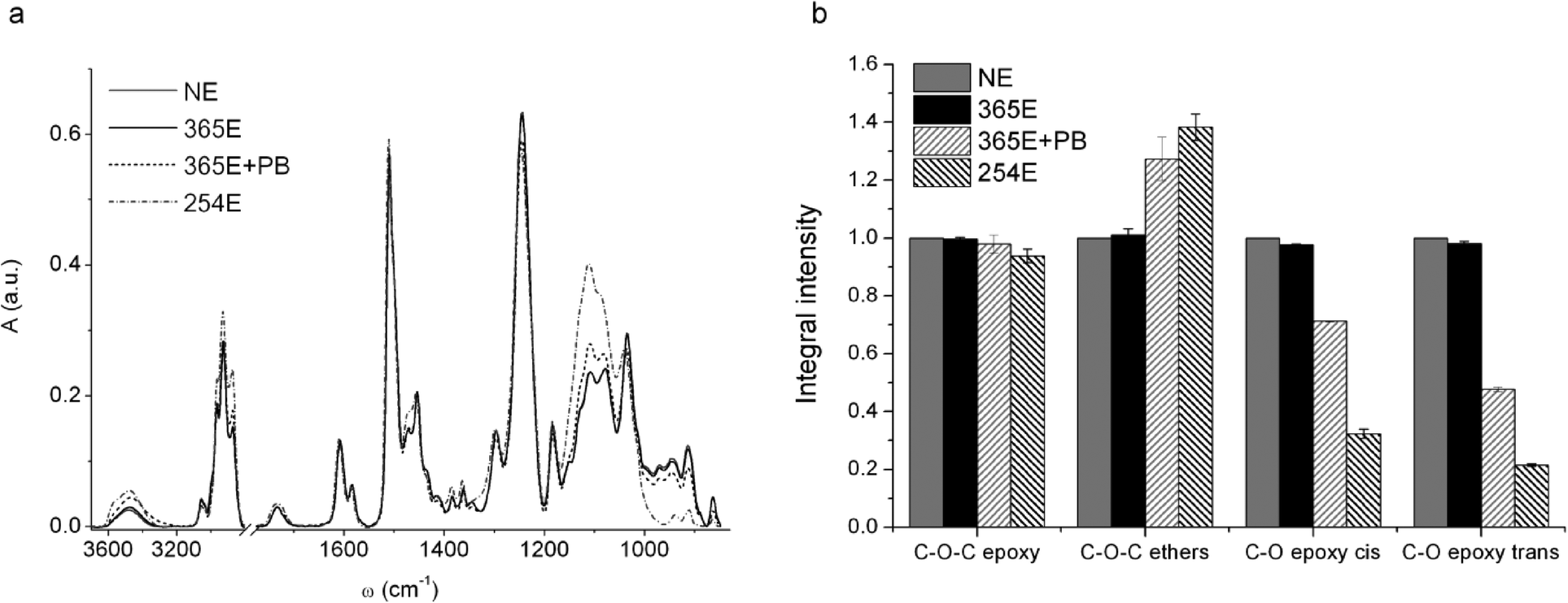 | ||
| Fig. 3 (a) FTIR spectra of SU-8 films prepared as detailed in Table 1. Spectra were normalized to the area of the peak centred at ~1500 cm−1; (b) relative intensity of C–O–C band of epoxy rings, of cis and trans C–O bands of substituted epoxides and of C–O–C band of ethers. | ||
The results confirm what is known from literature about the mechanism of polymerization of commercial SU-8 resist processed with conventional photolithography at 365 nm (Hg i-line). The basic constituents of SU-8 are the resin (bisphenol A novolac epoxy resin), a photo initiator (triarylsulfonium hexafluoroantimonate salts) and a solvent, typically either γ-butyrolactone (GBL) or cyclopentanone.1 The process of photo-polymerization at 365 nm starts when the film is exposed to UV-light, which promotes the activation of the photo-acid through the formation of radical species. During the post-bake, these radicals lead to the opening of epoxy rings of the monomers and the reaction propagates following the scheme of a classic acid catalyzed cationic reaction that ends with the resin reticulation. However, the spectrum of the 365E+PB sample suggests that the resin has still some intact epoxy rings (see Fig. 3), even after over-exposure (data shown in ESI†). In contrast, the polymerization reaction taking place when SU-8 is exposed to 254 nm light leads to higher concentrations of opened rings, even without the need of post-bake. Indeed, the intensities of residual epoxy ring peaks (see Fig. 3b) have lower average values than the ones of the samples exposed to 365 nm and post-baked. This clearly shows that 365 nm exposure followed by post-baking does not induce the activation of all available epoxy moieties, and that the conversion reaction from epoxy to ether C–O–C bonds in SU-8 layers already exposed to 365 nm could be enhanced by further exposure to 254 nm.
In order to validate our hypothesis, we prepared a film of SU-8 as detailed in the sketch of Fig. 4a. At the end of the process, four sectors of the sample can be distinguished: SU-8 unexposed and post-baked (A), SU-8 exposed to 365 nm and post baked (B), SU-8 unexposed to 365 nm, post-baked and exposed to 254 nm (C) and finally SU-8 exposed to 365, post-baked and exposed to 254 nm (D). A FTIR image was then collected at the intersection of the four areas; the results are shown in Fig. 4b. It clearly appears that the peak centred at 1280–1210 cm−1, related to C–O–C epoxy ring linkage, is not dramatically affected by exposure to 365 nm light (see A and B sectors) while the intensity of this band decreases more by exposure to 254 nm light (see sector C) and the decrement is even more pronounced when the 365 nm exposure is followed by 254 nm exposure (see sector D). Consistently, the peak at 1160–1050 cm−1, relative to C–O–C ether stretching, diagnostic for the polymer crosslinking, shows an opposite trend. Hence, the area already exposed to 365 nm undergoes a further activation after sequential exposure to 254 nm, through the opening of residual epoxy rings.
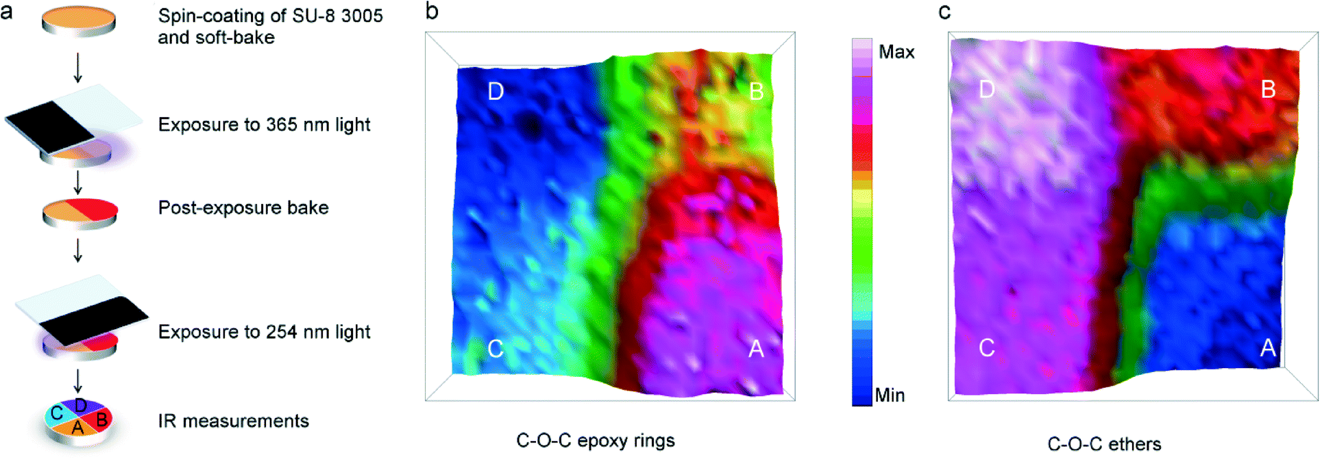 | ||
| Fig. 4 IR chemical images of a SU-8 film at different exposure conditions. (a) Scheme of the sample preparation. Sample regions were prepared as in the following: A – unexposed and post-baked, B – exposed to 365 nm and post-baked, C – unexposed to 365 nm, post-baked and exposed to 254 nm and D – exposed to 365, post-baked and exposed to 254 nm; (b) and (c) chemical images (170 × 170 μm2) obtained by integration of the spectral bands characteristic of the C–O–C epoxy ring (1280–1210 cm−1) and C–O–C ether (1160 and 1050 cm−1) respectively. | ||
The different behaviour of the SU-8 resist upon exposure to UV light of different wavelengths was exploited for optimizing a new SU-8 bonding protocol. The two halves of the device sketched in Fig. 1 were obtained by pattering SU-8 on CaF2/Si substrate, as detailed in the experimental section. The following exposure to 254 nm UV and a mild thermo-mechanical cycle (10 min at 70 °C and 40 bar) promoted the formation of additional ether bonds between the two halves, without affecting the integrity of the CaF2 windows. The key role in this soft bonding protocol is played by the exposure to UVC light that favours the formation of additional moieties on the surface of the resin, available for interlayer cross-linking. As a further confirmation of our hypothesis, when we tried to bond the two halves of the device using 365 nm UV light for the flood exposure step instead of 254 nm, there was no bonding between the two already patterned layers.
The tightness of the sealing was tested by following two different strategies. At first, FTIR imaging was again employed for testing the device filling. FPA images of the device continuously fed with DI water were collected. Representative chemical images of the device region where lateral channels intercept the main central channel are shown in Fig. 5. The images were obtained by integrating the spectral region between 3000–2800 cm−1, where vibrational bands of aliphatic SU-8 chains are, and water bending band centred at ~1645 cm−1. As can be clearly seen in Fig. 5a, signals of water are detectable only inside the channels, while signals of the resin are only detectable outside the channels. A 3D representation of the water filled device based on IR images is reported in ESI.† Chemical images of Fig. 5 also demonstrate the negligible interference of Omnicoat adhesion promoter in the IR spectra (see ESI† for additional details).
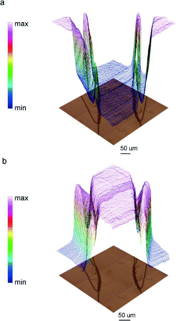 | ||
| Fig. 5 3D chemical images of the device region at the intersection between major and lateral channels (340 × 340 μm2) obtained integrating the acquired spectra (a) in the spectral region of methyl and methylene stretching bands (3000–2800 cm−1), and (b) the water bending mode (1770–1555 cm−1). Optical images are below. SU-8 and the water images are perfectly complementary. | ||
As a second validation, the sealing was monitored through a 48 hour test. A continuous flow of DI water at 8 μl h−1 was applied by a syringe pump connected to the central inlet channel. This flow rate corresponds to a complete exchange of the inner chamber volume in ~45 s. Optical images were then collected at 10X magnification every 15 min with a Leica stereoscopic microscope and a CCD camera remotely controlled. No leaks were observed during the 48 h test (see movie 1 in ESI†). We also tested the possibility to remove bubbles that sometimes accidentally form in the microfluidic device, by intentionally injecting air into the central chamber from one of the lateral channels. We could observe that the injected bubbles progressively disappeared under flowing water conditions, confirming the correct design of the microfluidic device (see movie 2 on ESI†). Furthermore, this test demonstrates that the extensive reticulation induced by UVC light exposure did not worsen the mechanical properties of the exposed resin for its use as structural layer.
MCF-7 lysis induction by osmotic stress application
The fabricated device was used to study the response of breast cancer MCF-7 cells to osmotic stress, induced by DI water. The experiment is divided in two parts, as described in the experimental section. The first covered four hours were needed for promoting the adhesion of MCF-7 cells onto the CaF2/Si surface; in the second experimental step, DI water was injected within the device in order to trigger the cellular lysis. Optical images of the central chamber of the microfluidic circuit were collected for monitoring morphological changes undergone by the cells during the process (see inset of Fig. 6b).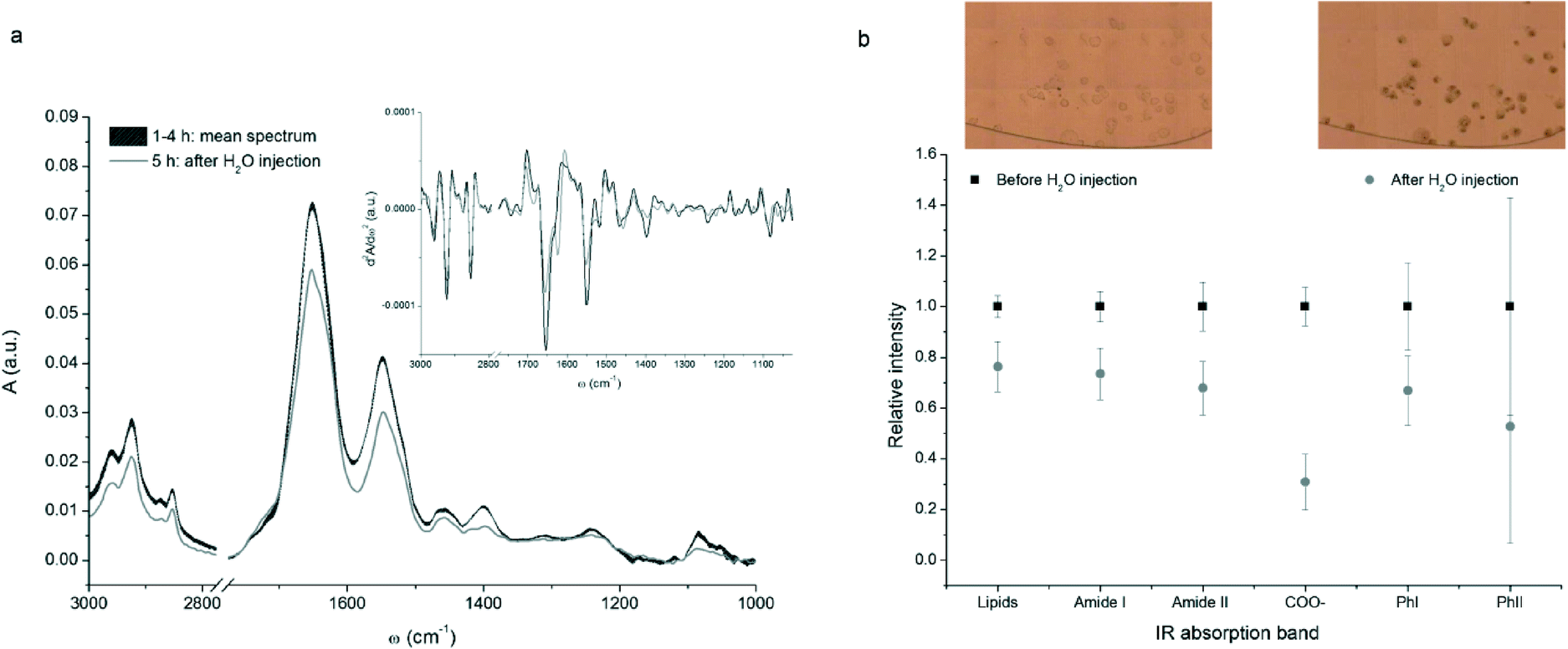 | ||
| Fig. 6 (a) FTIR spectra of a representative MCF-7 breast cancer cell acquired before (black curve) and after (grey curve) the water injection. The mean spectrum before injection was obtained averaging the results of the four measurements and the line thickness is proportional to the standard deviation. The inset shows the second derivatives of the spectra (Savitzky–Golay algorithm with 13 smoothing points); (b) normalized integrated intensity of some vibrational bands averaged on the measured cells, before and after the water injection (black squares and grey dots respectively). Bars represent the standard deviation of the mean. Integral values were calculated as spectral areas in the corresponding wavelength interval defined in Table 2. The inset shows an optical image of a part of the central chamber of the device filled with the cells, before and after the injection of DI water. | ||
Thirteen cells were selected and cyclically measured over the time of the whole experiment. Fig. 6a shows the series of spectra for a representative single MCF-7 cell. The assignment of the most relevant IR cellular band is reported in Table 2.
| Band position (cm−1) | Assignment | Principal components |
|---|---|---|
| a List of abbreviations: ν = stretching, δ = bending, s = symmetric, as = asymmetric. | ||
| 3000–2840 | ν as CH3, νas CH2 | Lipids |
| ν s CH3, νs CH2 | ||
| 1700–1610 | Amide I band: mainly ν C![[double bond, length as m-dash]](https://www.rsc.org/images/entities/char_e001.gif) O of peptide bond O of peptide bond |
Proteins |
| 1590–1480 | Amide II band: mainly ν C–N and δ C–N–H of peptide bond | Proteins |
| 1470 | δ CH2 of aliphatic chains | Lipids |
| 1430–1370 | ν s COO– | Proteins & lipids |
| 1260–1200 | PhI band: νas PO2− in phosphodiesters | Nucleic acids |
| 1110–1040 | PhII band: νs PO2− in phosphodiesters and ν C–OH | Nucleic acids & carbohydrates |
As can be seen from Fig. 6a, both intensity and position of the dominant spectral bands did not change throughout the first 4 hours. Indeed, during the first part of the experiment no striking changes in the IR absorption bands were expected. As a matter of fact, the physiological solution flow rate was low enough to consider negligible any cellular response induced by shear stress.44,45 Conversely, a sudden and significant decrease in the intensity of all absorption bands was detected when the physiological solution was replaced by DI water. This behaviour is common to all sampled cells.
In order to provide a semi-quantitative evaluation of the decrement of some diagnostic bands, integral intensities for each cell were divided in two sets, before and after water injection, and normalized to the average spectral intensity before the application of the osmotic stress. This procedure allowed to compare data from different cells, giving results independent from the individual cellular volume and biochemical content. Data obtained for the thirteen measured cells were then averaged and the results are plotted in Fig. 6b. A similar decrement in cellular lipids, proteins, and nucleic acids was highlighted by the analysis of signals related to methyl and methylene stretching bands, amide I and amide II bands and PhI band. The decrease of the PhII band, which accounts for both nucleic acids and carbohydrates variations, is comparable to the one of PhI band, but the standard deviation is much higher. This is due to the abrupt change in IR transparency of CaF2 below 1200 cm−1, that makes data more affected by sampling uncertainty.
The variations shown in Fig. 6 are consistent with the loss of biological material and the morphological changes undergone by cells due to lysis. The occurrence of cell lysis is confirmed also by the optical images of the cells before and after the injection of water, reported in the insets of Fig. 6b. As can be seen, initially cells were round shaped and transparent with a clear definition of the cellular membranes, while at the end of the experiment they became larger, loosing plasma membrane definition and integrity.
Moreover, the cell surface was covered by black bodies that generally characterize apoptotic and necrotic cells. Actually, DI water changes the osmolarity of the physiological medium, inducing hypotonic osmotic stress. This results in water uptake, cell swelling and subsequent cell lysis with release of cytoplasmic material into the extracellular environment. Moreover, cell swelling promotes the depolarization of the plasma membrane and the acidification of the cytosolic environment. The acidification can be deduced also by μ-FTIR data: the band centred at ~1400 cm−1, related to the carboxylic groups of amino acids, decreases in intensity and shifts from 1398 to 1393 cm−1 in the presence of DI water. Interestingly, this intensity reduction is even more pronounced than the one related to proteins, lipids and nucleic acids.
Furthermore, the analysis of the second derivative of the spectra (see inset of Fig. 6a) revealed an increase of two components of the Amide I band, centred at 1624 and 1695 cm−1, assigned to β-sheet coil and β-aggregates of proteins. Indeed, DI water is a strong denaturant agent for all macromolecules, and in particular for proteins, and promoted their aggregation.
Conclusions
In this paper we present a new bonding protocol for the fabrication of SU-8 based devices. Thanks to the formation of additional dangling bonds on already lithographed SU-8 layers by exposure to 254 nm UV light, the chemical bonding is achieved with a mild thermo-mechanical process using low temperatures and moderate pressures.These finding were applied in the bonding step of the fabrication of microfluidic devices for μ-FTIR studies of living cells. The test of fabricated chips allowed us to identify infrared biomarkers of the lytic process of MCF-7 breast cancer cells, induced by osmotic stress. The experiment here reported represented a good benchmark of our experimental setup, since it required both a precise control of the fluids and the absence of any leakages to allow the real time monitoring of the quick response of MCF-7 cells to the diffusion of a chemical inside the measurement chamber.
The mild bonding conditions make the procedure particularly suitable for any fragile substrate. CaF2 for FTIR microscopy analysis is an example, but the process has a general applicability and the protocol can be effortlessly extended to quartz, glass and silicon as well. It could be applied for the fabrication of multilayer SU-8 devices and it is expected to impact on other imaging techniques requiring optical paths completely free from any polymeric material, such as laser induced fluorescence (LIF). In the case of LIF, the auto-fluorescence of SU-8, especially in the near-UV range (355–425 nm) and up to 450–490 nm, hinder the use of fluorochromes emitting in these regions.46,47 This technique and several others suffering similar constraints will benefit from the overcoming of the aforementioned limitations.
Notes and references
- MicroChem, SU-8 3000 Data Sheet, http://microchem.com/pdf/SU-8%203000%20Data%20Sheet.pdf .
- R. Marie, S. Schmid, A. Johansson, L. Ejsing, M. Nordström, D. Häfliger, C. B. V. Christensen, A. Boisen and M. Dufva, Biosens. Bioelectron., 2006, 21, 1327–1332 CrossRef CAS PubMed.
- Y. Wang, C. E. Sims, P. Marc, M. Bachman, G. P. Li and N. L. Allbritton, Langmuir, 2004, 22, 7 Search PubMed.
- M. Nordström, R. Marie, M. Calleja and A. Boisen, J. Micromech. Microeng., 2004, 14, 1614–1617 CrossRef.
- W. E. Steger, Cryst. Res. Technol., 1989, 24, 634–634 CrossRef.
- H.-Y. N. Holman, M. C. Martin and W. R. McKinney, J. Biol. Phys., 2003, 29, 275–286 CrossRef CAS.
- B. H. Stuart, Biological Applications of Infrared Spectroscopy, John Wiley & Sons, 2004 Search PubMed.
- B. H. Stuart, in Infrared Spectroscopy: Fundamentals and Applications, John Wiley & Sons, Ltd, 2005, pp. 137–165 Search PubMed.
- L. Vaccari, G. Birarda, L. Businaro, S. Pacor and G. Grenci, Anal. Chem., 2012, 84, 4768–4775 CrossRef CAS PubMed.
- D. R. Whelan, K. R. Bambery, L. Puskar, D. McNaughton and B. R. Wood, Analyst, 2013, 138, 3891–3899 RSC.
- S. Venyaminov and F. G. Prendergast, Anal. Biochem., 1997, 248, 234–245 CrossRef CAS.
- F. Dousseau and M. Pezolet, Biochemistry, 1990, 29, 8771–8779 CrossRef CAS.
- A. Dong, P. Huang and W. S. Caughey, Biochemistry, 1990, 29, 3303–3308 CrossRef CAS.
- F. Dousseau, M. Therrien and M. Pézolet, Appl. Spectrosc., 1989, 43, 538–542 CrossRef CAS.
- M. K. Kuimova, K. L. A. Chan and S. G. Kazarian, Appl. Spectrosc., 2009, 63, 164–171 CrossRef CAS PubMed.
- M. J. Tobin, L. Puskar, R. L. Barber, E. C. Harvey, P. Heraud, B. R. Wood, K. R. Bambery, C. T. Dillon and K. L. Munro, Vib. Spectrosc., 2010, 53, 34–38 CrossRef CAS PubMed.
- D. Moss, M. Keese and R. Pepperkok, Vib. Spectrosc., 2005, 38, 185–191 CrossRef CAS PubMed.
- M. J. Nasse, S. Ratti, M. Giordano and C. J. Hirschmugl, Appl. Spectrosc., 2009, 63, 1181–1186 CrossRef CAS PubMed.
- P. Heraud, B. R. Wood, M. J. Tobin, J. Beardall and D. McNaughton, FEMS Microbiol. Lett., 2005, 249, 219–225 CrossRef CAS PubMed.
- L. Quaroni, T. Zlateva and E. Normand, Anal. Chem., 2011, 83, 7371–7380 CrossRef CAS PubMed.
- E. J. Marcsisin, C. M. Uttero, M. Miljkovic and M. Diem, Analyst, 2010, 135, 3227–3232 RSC.
- J. R. Powell, F. M. Wasacz and R. J. Jakobsen, Appl. Spectrosc., 1986, 40, 339–344 CrossRef CAS.
- K. Rahmelow and W. Hubner, Appl. Spectrosc., 1997, 51, 143–295 CrossRef.
- G. Birarda, G. Grenci, L. Businaro, B. Marmiroli, S. Pacor and L. Vaccari, Microelectron. Eng., 2010, 87, 806–809 CrossRef CAS PubMed.
- G. Birarda, G. Grenci, L. Businaro, B. Marmiroli, S. Pacor, F. Piccirilli and L. Vaccari, Vib. Spectrosc., 2010, 53, 6–11 CrossRef CAS PubMed.
- G. Grenci, G. Birarda, E. Mitri, L. Businaro, S. Pacor, L. Vaccari and M. Tormen, Microelectron. Eng., 2012, 98, 698–702 CrossRef CAS PubMed.
- E. Mitri, A. Pozzato, G. Coceano, D. Cojoc, L. Vaccari, M. Tormen and G. Grenci, Microelectron. Eng., 2013, 107, 6–9 CrossRef CAS PubMed.
- E. C. F. Liang, Fracture of Calcium-fluoride, ProQuest, UMI Dissertations Publishing, 1982 Search PubMed.
- J. Yan, J. Tamaki, K. Syoji and T. Kuriyagawa, Int. J. Adv. Manuf. Technol., 2004, 24, 640–646 CrossRef PubMed.
- J. L. Ladison, J. J. Price, J. D. Helfinstine and W. R. Rosch, Hardness, elastic modulus, and fracture toughness bulk properties in corning calcium fluoride, 2005.
- S. Lupi, A. Nucara, A. Perucchi, P. Calvani, M. Ortolani, L. Quaroni and M. Kiskinova, J. Opt. Soc. Am. B, 2007, 24, 959–964 CrossRef CAS.
- S. Keller, G. Blagoi, M. Lillemose, D. Haefliger and A. Boisen, J. Micromech. Microeng., 2008, 18, 125020 CrossRef.
- Z. Movasaghi, S. Rehman and I. U. Rehman, Appl. Spectrosc. Rev., 2008, 43, 134–179 CrossRef CAS.
- V. N. Vernekar, D. K. Cullen, N. Fogleman, Y. Choi, A. J. García, M. G. Allen, G. J. Brewer and M. C. Laplaca, J. Biomed. Mater. Res., Part A, 2009, 89, 138–151 Search PubMed.
- M. Marelli, G. Divitini, C. Collini, L. Ravagnan, G. Corbelli, C. Ghisleri, A. Gianfelice, C. Lenardi, P. Milani and L. Lorenzelli, J. Micromech. Microeng., 2011, 21, 045013–045020 CrossRef.
- M. Hennemeyer, F. Walther, S. Kerstan, K. Schürzinger, A. M. Gigler and R. W. Stark, Microelectron. Eng., 2008, 85, 1298–1301 CrossRef CAS PubMed.
- K. V. Nemani, K. L. Moodie, J. B. Brennick, A. Su and B. Gimi, Mater. Sci. Eng., C, 2013, 33, 4453–4459 CrossRef CAS PubMed.
- M. Lacroix and G. Leclercq, Breast Cancer Res. Treat., 2004, 83, 249–289 CrossRef CAS.
- G. Birarda, Doctoral Thesis, University of Trieste, 2011 Search PubMed.
- J. Kim, I. Kim and K. W. Paik, Investigation of various photo-patternable adhesive materials and their processing conditions for MEMS sensor wafer bonding, 2011.
- N. E. Glavitz, L. A. Starman, R. A. Coutu Jr and R. L. Johnston, Effects of SU-8 cross-linking on flip-chip bond strength when assembling and packaging MEMS, 2011.
- S. Tuomikoski and S. Franssila, Sens. Actuators, A, 2005, 120, 408–415 CrossRef CAS PubMed.
- A. Krebs, T. Knoll, D. Nußbaum and T. Velten, Microsyst. Technol., 2012, 18, 1871–1877 CrossRef CAS PubMed.
- J. Rahimzadeh, F. Meng, F. Sachs, J. Wang, D. Verma and Susan Z. Hua, J. Cell. Physiol., 2011, 301, 7 Search PubMed.
- H. Lu, L. Y. Koo, W. M. Wang, D. A. Lauffenburger, L. G. Griffith and K. F. Jensen, Anal. Chem., 2004, 76, 8 Search PubMed.
- M. Del Mar Barrios-Romero, A. G. Crevillén and J. C. Diez-Masa, J. Sep. Sci., 2013, 36, 2530–2537 CrossRef PubMed.
- T. Sikanen, L. Heikkilä, S. Tuomikoski, R. A. Ketola, R. Kostiainen, S. Franssila and T. Kotiaho, Anal. Chem., 2007, 79, 6255–6263 CrossRef CAS PubMed.
Footnote |
| † Electronic supplementary information (ESI) available: ESI 1: effects of silicon layers and Omnicoat on the IR transparency of CaF2; ESI 2: device fabrication and assembly of the system; ESI 3: behavior of SU-8 resist upon exposure at UV light of different wavelength; ESI 4: behavior of the device under experimental conditions. ESI 4 contains three movies. See DOI: 10.1039/c3lc50878a |
| This journal is © The Royal Society of Chemistry 2014 |