PDMS based coplanar microfluidic channels for the surface reduction of oxidized Galinstan†
Guangyong
Li
a,
Mitesh
Parmar
a,
Daeyoung
Kim
b,
Jeong-Bong (JB)
Lee
b and
Dong-Weon
Lee
*a
aSchool of Mechanical Engineering, Chonnam National University, Gwangju 500757, Republic of Korea. E-mail: mems@chonnam.ac.kr; Fax: +82 62 5300337; Tel: +82 62 5301669
bDepartment of Electrical Engineering, The University of Texas at Dallas, Richardson, TX 75080, USA
First published on 2nd October 2013
Abstract
Galinstan has the potential to replace mercury – one of the most popular liquid metals. However, the easy oxidation of Galinstan restricts wide applicability of the material. In this paper, we report an effective reduction method for the oxidized Galinstan using gas permeable PDMS (polydimethlysiloxane)-based microfluidic channel. The complete study is divided into two parts – reduction of Galinstan oxide and behavior of reduced Galinstan oxide in a microfluidic channel. The reduction of Galinstan oxide is discussed on the basis of static as well as dynamic angles. The contact angle analyses help to find the extent of reduction by wetting characteristics of the oxide, to optimize PDMS thickness and to select suitable hydrochloric acid (HCl) concentration. The highest advancing angle of 155° and receding angle of 136° is achieved with 200 μm thick PDMS film and 37 wt% (weight percent) HCl solution. The behavior of reduced Galinstan oxide is analyzed in PDMS-based coplanar microfluidic channels fabricated using a simple micromolding technique. Galinstan in the microfluidic channel is surrounded by another coplanar channel filled with HCl solution. Due to the excellent permeability of PDMS, HCl permeates through the PDMS wall between the two channels (interchannel PDMS wall) and achieves a continuous chemical reaction with oxidized Galinstan. A Lab VIEW controlled syringe pump is used for observing the behavior of HCl treated Galinstan in the microfluidic channel. Further optimization of the microfluidic device has been conducted to minimize the reoxidation of reduced Galinstan oxide in the microfluidic channel.
1 Introduction
The liquid metals have attracted wide attention for power electronics and electronic devices due to their unique physical properties, such as thermo-conductivity, electrical conductivity and electron mobility. Mercury is the best known of the liquid metals (mercury, gallium, gallium alloy aluminum, tin, etc.) and remains the only liquid metal at room temperature. Unfortunately, the toxicity of mercury poses a challenge for its widespread applications. Therefore, it is necessary to find an alternative material for mercury based applications.Galinstan is a commercially available (from Geratherm Medical AG, Germany) eutectic GaInSn metal alloy (68.5%, 21.5% and 10% by weight, respectively). Considering its outstanding properties such as low melting point (−19 °C), high electrical conductivity (3.46 × 10⁶ S m−1), high boiling point (1300 °C), good thermal conductivity (16.5 W m−1 K−1) and ultralow vapor pressure, it can be a suitable replacement for mercury in many applications such as thermometers,1 coolants,2 RF micro switches,3 magneto-hydrodynamic pumps,4 microvalves,5 resonators,6 antennas,7–12 energy harvesting13 and tunable frequency selective surfaces (FSS).14 The working mechanism of tunable FSS devices can be represented by an equivalent circuit based on change in capacitance and/or inductance. This capacitance change depends largely on the movement of Galinstan. Hence, the easy movement of Galinstan is important in the efficient working of many applications.
However, the surface of Galinstan is instantly oxidized under ambient conditions and it behaves more like a gel rather than a true liquid, adhering to almost any solid surface. This oxide layer behaves like a solid and remains elastic unless it experiences a yield stress. The viscous nature of the oxidized Galinstan originates from gallium oxide (Ga2O3 and Ga2O) and it has a significant stickiness problem affecting the easy movement of the liquid metal alloy.15 In order to overcome this stickiness problem, efforts have been made to avoid the oxidation of Galinstan in recent years. One of the ways to avoid oxidation is to immerse Galinstan in a deoxygenated solution. Hutter et al. have used solutions such as polyethylene glycol (PEG) and deoxygenated silicone oil to prevent oxidation of the gallium–indium (Ga–In) alloy.16 According to Liu et al. Galinstan behaves like a true liquid metal in sub-ppm oxygen environments.17 However, this requires a vacuum-sealed hermetic packaging which can be very complex as well as costly. Hence, efforts are made to use either oxidized Galinstan or to remove the complete oxide layer. In order to avoid oxidation of Galinstan, Sivan et al. have coated Galinstan droplets with semiconductors or insulators either by rolling them over a powder bed or immersing them in colloidal solutions.18 Kim et al. reported a micro pillar array based super-lyophobic polydimethylsiloxane (PDMS) micro-tunnel for oxidized Galinstan.19 However, this has a limitation in applying to 3-dimensional structures. Chen et al. presented a Teflon coated channel to overcome this sticking of oxidized Galinstan since it is surrounded by Teflon solution.20 Similarly, Thelen et al. have used polyvinyl alcohol (PVA) to stabilize oxide layer of Ga–In liquid metal.21 Nevertheless, these solutions can obstruct the movement of the oxidized Galinstan. Zrnic et al. found that the gallium oxide layer can be removed by treating the surface with diluted HCl solution.22 As gallium oxide is one of the constituents in the oxidized Galinstan, the oxidized Galinstan can also be reduced using HCl solution. This idea was later implemented by Kocourek et al.23 and Dickey et al..24 However, the difficulty in both the implementations is the complete immersion of Galinstan droplets into HCl solution which limits its applicability. The chemical aspects of HCl treated Galinstan along with its wetting characteristics are reported by Kim et al.25
The objective of this paper is to formulate and report a suitable reduction process for the oxidized Galinstan in Galinstan movement-based microfluidic applications using PDMS (with high intrinsic permeability to gases).26–30 The complete study is divided into subsections on contact angle measurements (static and dynamic) and microfluidic applications. Galinstan moving in microfluidic channels can be constantly maintained in a true liquid phase at room temperature when it is treated continuously by an HCl solution filled coplanar surrounding channel. In addition, the recovery of the non-wetting characteristics of Galinstan droplets is discussed before and after treating the oxidized Galinstan with various concentrations of HCl solution. Finally, the microfluidic device is further optimized to minimize the reoxidation of reduced Galinstan oxide in microfluidic channels.
2 Reduction of Galinstan oxide and its wetting characteristics
2.1 Static contact angle
The contact angle is an experimentally observable quantity that describes the wetting property of a liquid in contact with a solid surface. It can be quantified using Young's equation31 as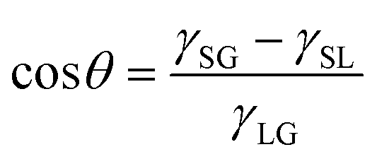 | (1) |
As discussed earlier, diluted HCl solution can be used to remove the gallium oxide layer.22 Hence, first of all, the effect of HCl solution on PDMS needs to be studied. The details of the study have been discussed in the ESI† (supplementary Fig. S1). According to these results, no noticeable damage of PDMS pillars is observed even after immersing the PDMS pillar-based device in 37 wt% HCl for 60 hours. Therefore, in order to analyse the recovery of the non-wetting characteristics of reduced Galinstan oxide droplets on the PDMS surface, the contact angle changes of oxidized Galinstan droplets are measured before and after the reduction using HCl solution. For this, a PDMS film is placed over HCl solution (200 μl). Galinstan (~8 μl) is dropped on the PDMS surface using a syringe. The droplet formed during the dispensing of Galinstan does not form a spherical shape, resulting in a deformed shape as shown in Fig. 1(A1–A2). This is attributed to the oxidation of the surface of Galinstan.11,18,25 After the permeation of HCl through the PDMS film, it initiates the reduction of oxidized Galinstan. As the oxide layer is removed, the reduced Galinstan oxide surface (with higher surface tension compared to the oxidized one25) attains a true liquid nature, and the deformed shape becomes spherical as shown in Fig. 1(B1–B2) which is the basis of Young's eqn (1). Due to this, there is a noticeable change in the contact angle indicating the change in wetting characteristics of the droplet. Here, the droplet contact angle measurements are performed using a charge-coupled device (CCD) camera (15 frames per second) along with an in-house developed image processing MATLAB program.
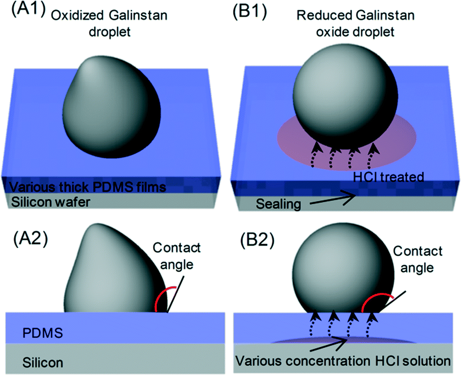 | ||
| Fig. 1 Sketch of 3-dimensional view and side view of (A1, A2) oxidized Galinstan droplet and (B1, B2) reduced Galinstan oxide droplet using HCl solution. | ||
However, the time required for the reduction of oxidized Galinstan depends on the permeation of HCl and its reactivity towards the oxide layer. In the case of HCl permeation through the PDMS, the PDMS thickness as well as the concentration of the HCl solution is an important factor. Hence, a detailed study on the effect of thickness and HCl solution concentration variation on permeation and oxidized Galinstan reduction is necessary. For further validation towards the permeability of PDMS film, the HCl permeation time (through PDMS films of different thickness) is observed using pH paper.
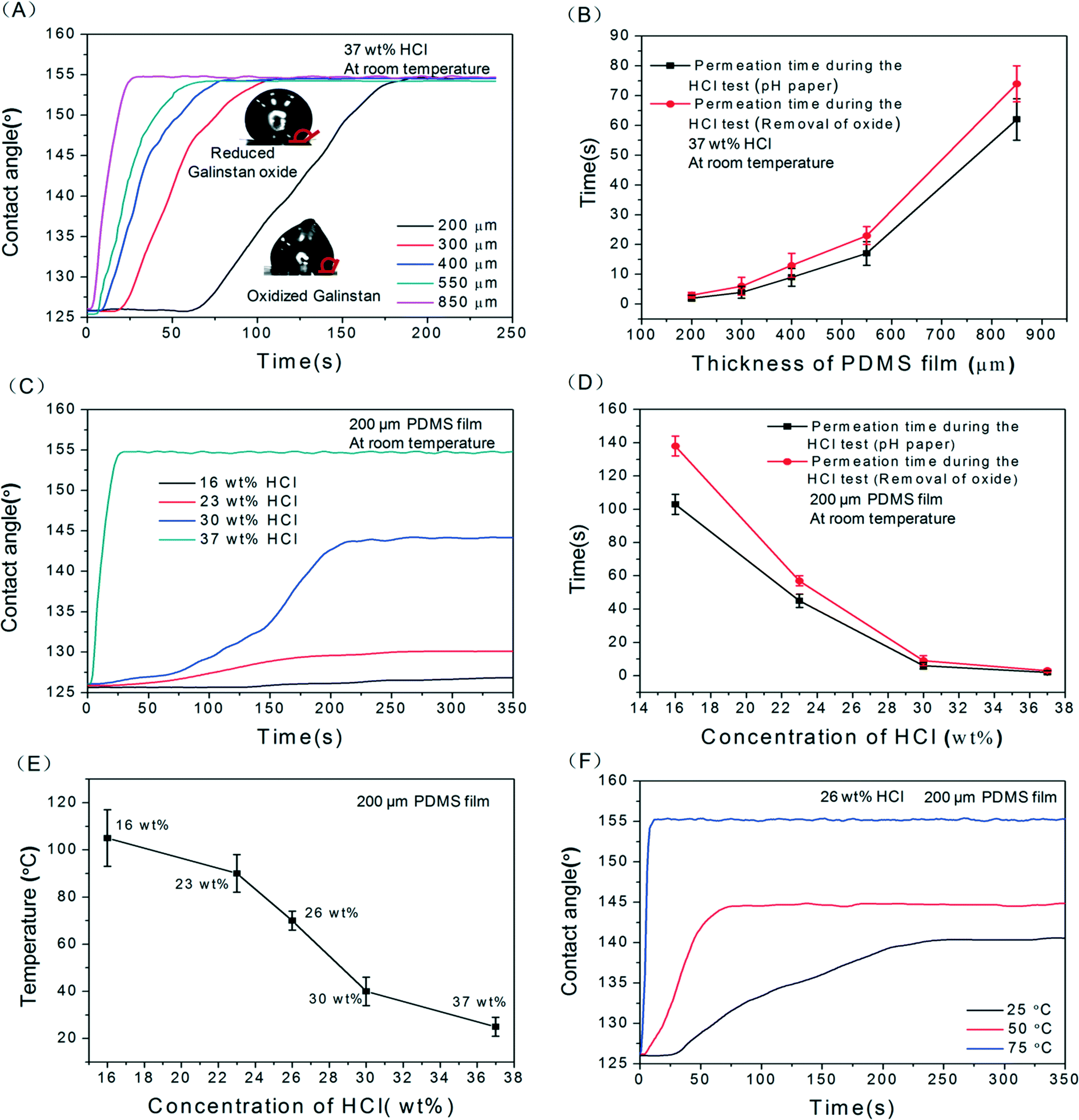 | ||
| Fig. 2 (A) ~8 μl reduced Galinstan oxide droplet contact angles as a function of time for various PDMS films; (B) the comparison between the permeation time obtained during the reduction of oxidized Galinstan and pH paper test for various PDMS thicknesses; (C) ~8 μl reduced Galinstan oxide droplet contact angles as a function of diffusion time of various HCl concentrations; (D) the comparison between permeation time obtained during the reduction of oxidized Galinstan and pH paper test for various HCl concentrations; (E) optimum temperature for reduction of Galinstan oxide using various concentrations of HCl solution; (F) ~8 μl reduced Galinstan oxide droplet contact angles as a function of time for various operating temperatures. | ||
Fig. 2(C) shows the change in contact angle of ~8 μl Galinstan droplet (from the oxidized to reduced state) over time for different HCl concentrations with 200 μm thick PDMS film. Because the contact angle represents the wetting characteristics of Galinstan oxide as discussed before, the change in contact angle indicates the extent of reduction. Here, the contact angle of reduced Galinstan oxide varies from ~125° up to ~127°, ~130°, ~145° and ~155° in 16 wt%, 23 wt%, 30 wt% and 37 wt% concentrations of HCl solution respectively. The efficiency of reduction is observed to decrease with increasing HCl dilution. This also reflects the reactivity between oxidized Galinstan and dilute HCl solution. One of the reasons for the less efficient reduction of oxidized Galinstan, using low concentration (<37 wt%) HCl solutions, is the low permeability of these solutions. In addition to this, the reactivity of low concentration (<37 wt%) HCl solutions also decreases with the increase in dilution of HCl solutions. This can be confirmed by observing the rate of change of contact angle for the droplet. Fig. 2(D) shows the comparison between the permeation time of HCl calculated during reduction of Galinstan oxide and the permeation time obtained utilizing pH paper. As can be observed, 37 wt% HCl quickly permeates through the PDMS film compared to other lower concentrations of HCl solution. This can be attributed to the comparatively higher vapor pressure of 37 wt% HCl solution (16 kPa at 20 °C). To summarize this analysis, 37 wt% HCl solution reduces the oxidized Galinstan droplet quickly and completely, allowing it to be a true liquid with non-wetting characteristics even at room temperature.
2.2 Dynamic contact angle
The contact angle of a liquid moving over a surface is termed as the dynamic contact angle. Along with the static contact angle, in order to quantify the wetting property of oxidized Galinstan droplets, the dynamic contact angle (sliding angle and advancing–receding angle) is particularly important. The relation of sliding angle to the advancing and receding contact angles is presented in eqn (2) as:32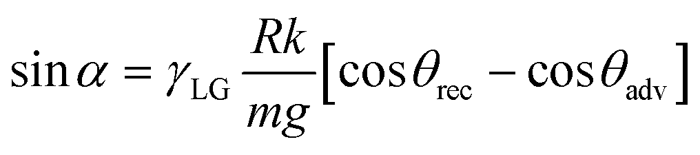 | (2) |
Out of all the different concentrations of HCl solutions (16–37 wt%), only 37 wt% HCl completely reduces the oxidized Galinstan at room temperature. Although 30 wt% HCl solution somehow reduces the oxide layer, the oxide removal is incomplete. The contact angle measured for the incompletely reduced oxidized Galinstan is ~145° (Fig. 2(C)). Hence, the sliding angle for the completely reduced Galinstan oxide (using 37 wt% HCl solution) is relatively smaller compared to incompletely reduced Galinstan oxide (using 30 wt% HCl solution). Although the existence of a partial oxide layer makes it adhere to the PDMS surface, the effect of gravity on the Galinstan droplet will overcome the adhesive force and result in sliding of the droplet on a tilted stage with the increase in angle of tilting. Fig. 3 shows a graph depicting the relationship between Galinstan droplet volume and its sliding angle on PDMS with 37 wt% and 30 wt % HCl solution. As can be observed in the figure, the sliding angle of the Galinstan droplet decreases with increasing volume. However, for less concentrated HCl solution (<30 wt%), the effect of gravity on incompletely reduced Galinstan oxide droplets could not overcome the adhesive force even when the tilting angle reached 90° and hence the sliding angle does not exist. For this study, it can be said that 37 wt% HCl solution helps in complete reduction of the oxidized Galinstan and allows fast recovery of non-wetting characteristics. The result is found to be identical to the conclusion discussed previously.
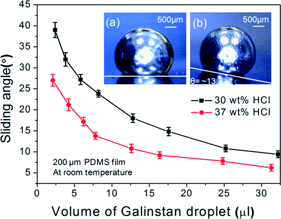 | ||
| Fig. 3 Reduced Galinstan oxide droplet sliding angles on PDMS film with 37 wt% and 30 wt% HCl solutions: (a) reduced Galinstan oxide droplet (12.5 μl) placed on level plate and (b) sliding on tilted plate. | ||
The variation in the advancing and receding contact angles of the Galinstan droplet on the PDMS with various HCl solutions (0–37 wt%) is shown in Fig. 4. During continuous addition of Galinstan, the oxide layer is continuously replaced by unoxidized Galinstan and hence the contact angle (~155°) remains constant throughout the adding process for various concentrations of HCl solution. However the contact angle of oxidized Galinstan is 125° before HCl treatment as shown in Fig. 2(A). This can be explained by the fact that the oxide layer is formed instantly after the Galinstan droplet comes into contact with air and the static contact angle changes from 155° (for unoxidized Galinstan) to 125° (for oxidized Galinstan). For less concentrated HCl solution (<30 wt%), the receding angle appears very low (~60°, ~41°, ~22° and ~6° in 26 wt%, 23 wt%, 16 wt% and 0 wt% conditions respectively) due to incomplete or absence of reduction (supplementary Fig. S3, ESI†). The receding angle would have been even lower than 6° if the measurement had not been ended prematurely by the liquid disconnection during the receding (removal) process. For 30 wt% concentration of HCl solution, the contact angle decreased to a minimum value (96°) and increased to ~116° with removal of Galinstan. This may be due to incomplete reduction of Galinstan oxide surface. The contact angle will increase until the suction force overcomes gravity as well as the adhesive force of the reduced Galinstan oxide droplet, and reaches a maximum value during the receding process. It is observed that the highest concentration of HCl solution makes the smallest Galinstan droplet contact angle hysteresis (difference value ~19° between advancing angle ~155° and receding angle ~136° for 37 wt% HCl solution) and allows recovery of its non-wetting characteristics at room temperature. Based on the above discussion, it can be concluded that the reduction process of oxidized Galinstan depends on the HCl concentration. Therefore, the extent of reduction deteriorates with a decrease in HCl concentration.
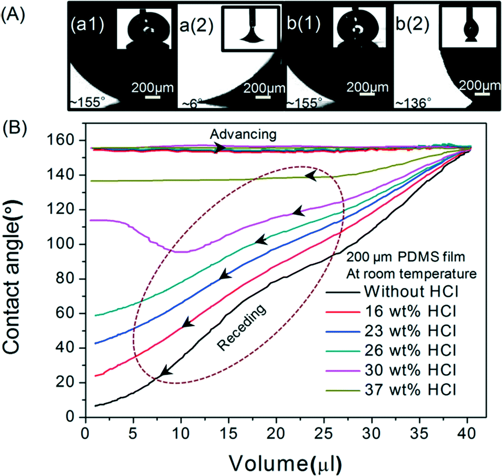 | ||
| Fig. 4 (A) Photograph of advancing angle and receding angle for oxidized Galinstan (a1, a2) and reduced Galinstan oxide (b1, b2) respectively; (B) Galinstan droplet advancing and receding angle on PDMS film with various concentrations of HCl solution. | ||
3 Reduced Galinstan oxide in coplanar microfluidic channel
3.1 Realization of microfluidic channel
To demonstrate the behavior of reduced Galinstan oxide in a micro-channel, a coplanar microfluidic channel based PDMS device was designed. The Galinstan containing channel is surrounded by a channel filled with HCl solution. As mentioned before, the HCl concentration as well as the thickness of the interchannel PDMS wall can influence the oxide removal from oxidized Galinstan. After carefully studying the permeability of various concentrations of HCl solution through PDMS films of different thicknesses, the complete reduction of the oxidized Galinstan at room temperature led to the interchannel wall of thickness 200 μm for 37 wt% HCl solution.Based on the above analysis, the coplanar microfluidic channel device is fabricated using conventional micro-molding technology as shown in Fig. 5. The coplanar microfluidic channel mold is made from SU-8 2050 photoresist (PR) on a silicon wafer. PDMS solution is coated on the coplanar microfluidic channel-mold using standard rapid prototyping methods. After curing, the top PDMS based coplanar microfluidic channel layer is gently peeled off from the mold. The PDMS layer (thickness: 3 mm) has two coplanar channels (cross-sectional area: 600 μm width, 100 μm height) containing 5 ports (diameter: 2.4 mm) to inject Galinstan as well as HCl solution and to apply air pressure for driving the Galinstan droplet. After oxygen plasma activation,33,34 the PDMS channel layer and the glass slide (as foundation base) are bonded together to complete the channel formation. After fabrication, an experimental setup comprising a CCD camera system and Lab VIEW controlled syringe pump is used to characterize the behavior of reduced Galinstan oxide in the microfluidic channel (supplementary Fig. S4, S5 and supporting video SV1, ESI†). This reduced Galinstan oxide behavior depends on air pressure and the flow rate. For characterizing and enhancing the Galinstan feasibility for electronic device applications like FSS, the conditions in which the Galinstan is filled into the microfluidic channel, separated and later moved; and the accurate movement of a reduced Galinstan oxide droplet using a Lab VIEW controlled syringe pump are necessary.
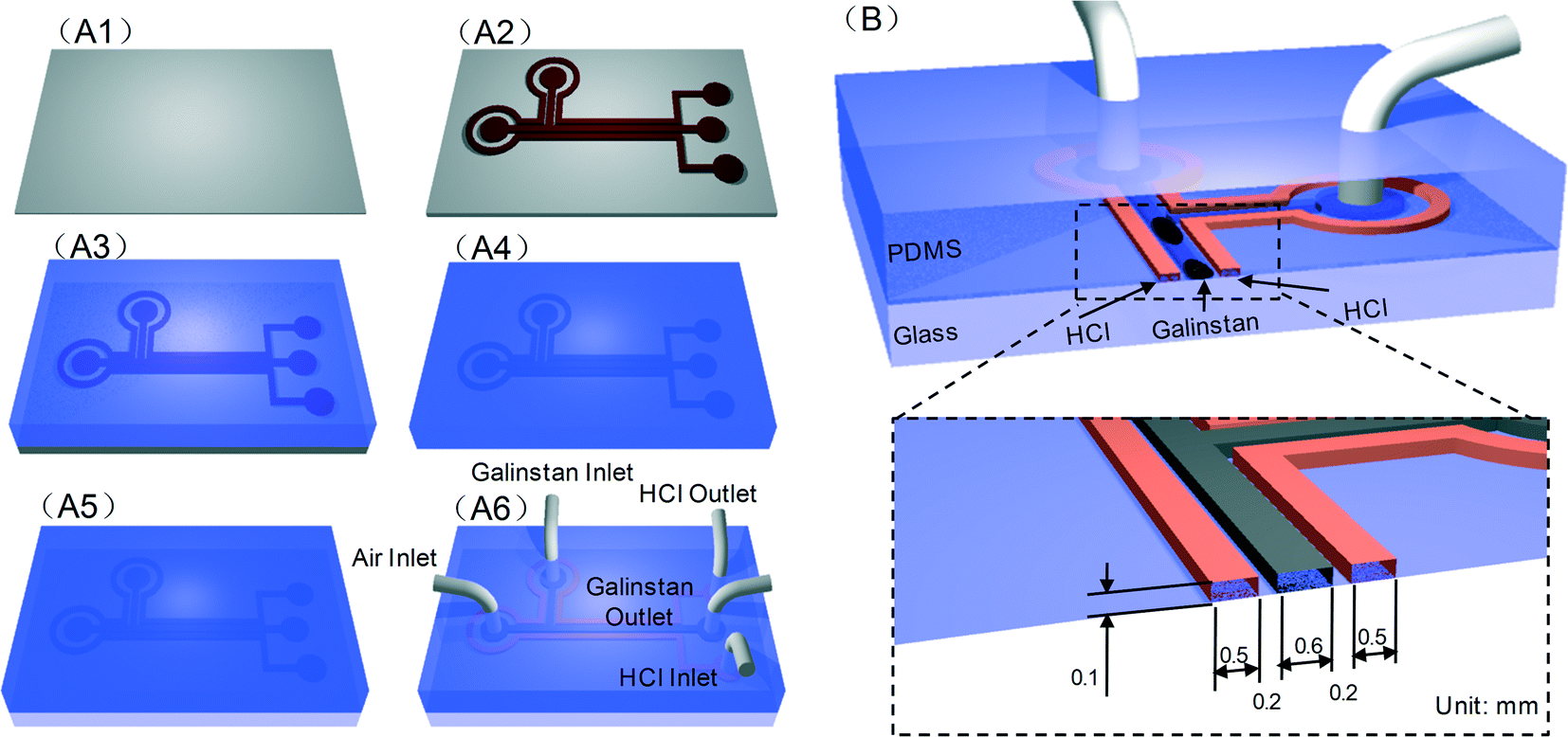 | ||
| Fig. 5 Fabrication sequence of PDMS channel: (A1) silicon wafer, (A2) SU-8 PR mold on Si wafer, (A3) PDMS coating, (A4) PDMS peeled off from the mold, (A5) PDMS–Glass bonding, (A6) injection of Galinstan in microfluidic channel surrounded by another coplanar channel filled with HCl solution; (B) cross-section of structure and channel size. | ||
3.2 Behavior of reduced Galinstan oxide in the microfluidic channel
The reduced Galinstan oxide seems to behave like a true liquid. The time required for the permeation of HCl (37 wt%) through the 200 μm thick PDMS interchannel wall and to reduce the oxidized Galinstan is ~300 s (supplementary Fig. S6, ESI†). The longer duration required for permeation as well as the reduction of oxidized Galinstan in the microfluidic channel compared to the complete reduction of oxidized Galinstan placed on 200 μm PDMS film is due to the limited surface area for the reaction (area: 126 mm length, 0.1 mm height).
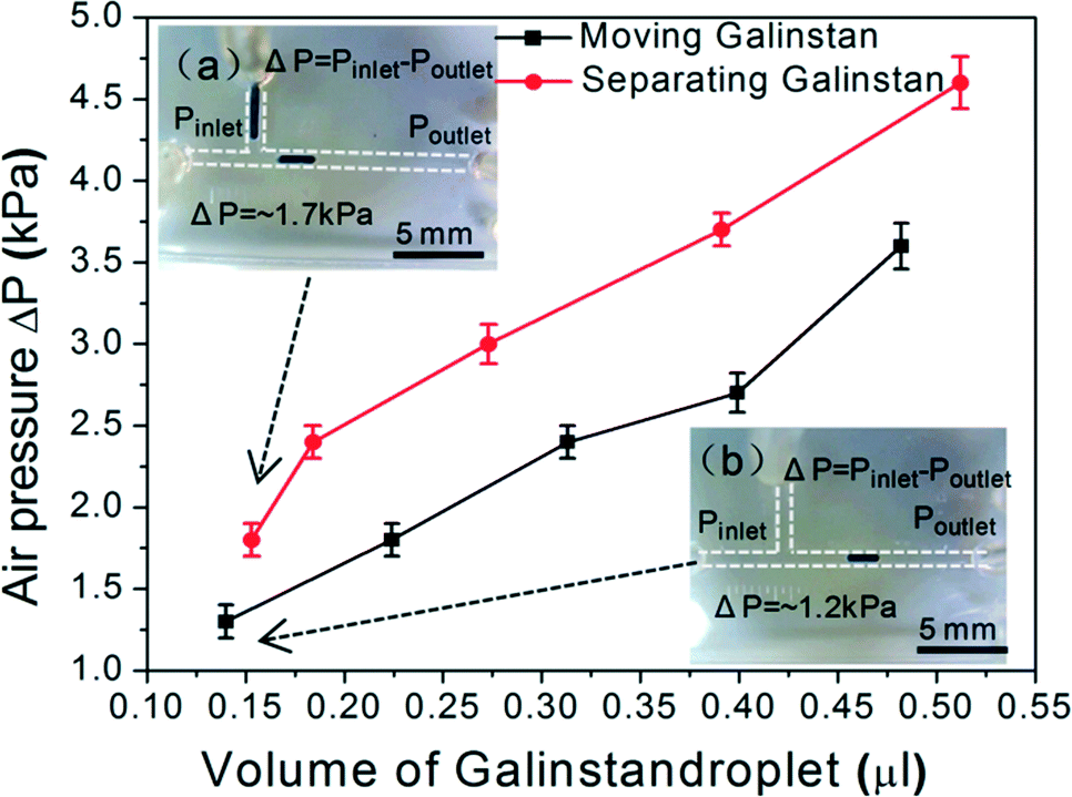 | ||
| Fig. 6 Separating and moving a reduced Galinstan oxide droplet in a microfluidic channel and its dependence on pressure; photographs (a–b) of separation and movement of reduced Galinstan oxide droplet. | ||
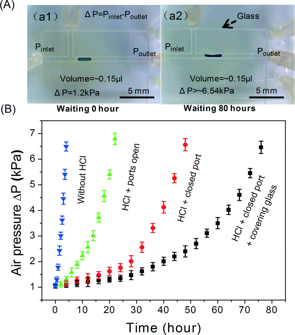 | ||
| Fig. 7 (A) Photographs a1–a2 showing the initial and final (after 80 hours) shape of reduced Galinstan oxide for the conditions in which HCl solution is present in the microfluidic channel, the HCl inlet and outlet are closed, and glass is covering the PDMS channel surface; (B) air pressure as a function of reoxidation time under various conditions. | ||
Due to the non-wetting characteristics of the reduced Galinstan oxide droplet using 37 wt% HCl solution as discussed before, the minimum pressure required to drive the Galinstan droplet offers information about the absence or presence of the oxide layer and in turn helps to measure the reoxidation time of the reduced Galinstan oxide. The reoxidation time is measured by optimizing the air pressure required to drive the Galinstan at different times under various conditions.
Fig. 7 shows the required pressure difference to drive the reduced Galinstan oxide droplet (0.15 μl) as a function of reoxidation time under various conditions (absence/presence of HCl solution in the microfluidic channel; opening or closing the HCl inlet and outlet; covering glass present on PDMS channel or not). Firstly, the Galinstan droplet (0.15 μl) was moved in the channel when the pressure difference reached ~1.2 kPa (Fig. 7(A-a1)). The required pressure difference to drive the Galinstan droplet increases with time until the Galinstan droplet shape is changed (Fig. 7(A-a2)). This change in shape of the droplet indicates the presence of the oxide layer and hence, shows a variation in the wetting characteristics. As can be observed from Fig. 7(B), the reoxidation time is 4 hours, 20 hours and 48 hours respectively under the first set of conditions (removing HCl solution from the microfluidic channel), second conditions (leaving the HCl solution in the microfluidic channel and opening the HCl inlet and outlet) and third conditions (leaving the HCl solution in microfluidic channel and closing the HCl inlet and outlet). For fourth set of conditions (leaving the HCl solution in the microfluidic channel, closing the HCl inlet and outlet, and covering the PDMS channel surface with glass to reduce evaporation of HCl), the Galinstan droplet shape is changed when a pressure difference of ~6.54 kPa is applied to drive it after 80 hours (Fig. 7(A-a2)). The reason is that the Galinstan droplet is oxidized and adheres to the inner wall after 80 hours. The volatilization rate of HCl under the fourth set of conditions is lower than that under the previous three conditions. Therefore, the time for which the Galinstan droplet maintains a true liquid phase and a stable structure in the microfluidic channel is the longest.
To control the movement (linear and reciprocating motion) of Galinstan droplets, an experimental setup including a syringe pump, computer along with Lab VIEW data acquisition system and CCD camera is used. The details of this setup are provided in the supplementary information (supplementary Fig. S4, S5 and supporting video SV1, ESI†). In brief, the microchannel is connected to a Lab VIEW controlled syringe pump. This pump can generate the necessary pressure difference to move the Galinstan droplet in reciprocating (forward or reverse) directions. Latter, the velocities of the reduced Galinstan oxide droplet as a function of time with various air flow rates are obtained by using a video process.
Fig. 8(A) shows the velocities of linear movement of reduced Galinstan oxide droplets (~0.15 μl) with various air flow rates (0.6, 1.2, 1.8, 2.4 and 3.0 ml min−1) controlled by the syringe pump (supporting video SV3, ESI†). At first, the air is injected into the inlet of the microfluidic channel at particular flow rates (mentioned above) and used for driving the droplet. The reduced Galinstan oxide droplet moves only when the pressure difference exceeds a certain value depending on volume of the droplet (for example, ~0.15 μl requires 1.2 kPa pressure difference) as discussed before. The velocity of the droplet increases with time and tends to saturate later. This saturation of droplet velocity may be due to the fixed air flow rate and the constant resistive (intermolecular adhesive) force on the movement of the reduced Galinstan oxide droplet. As expected, a larger flow rate results in a higher value for maximum velocity of the reduced Galinstan oxide droplet.
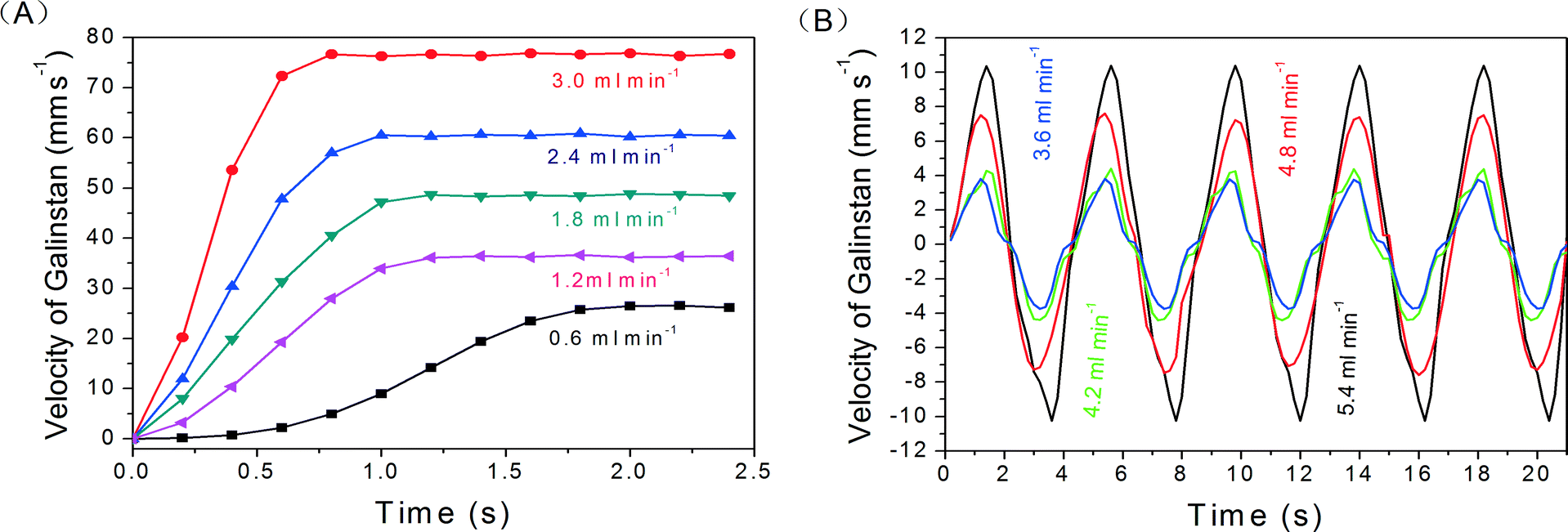 | ||
| Fig. 8 Velocity of reduced Galinstan oxide droplet for (A) linear movement with various flow rates; (B) reciprocating movement with various flow rates. | ||
As shown in Fig. 8(B), the velocities of reciprocating movement of reduced Galinstan oxide droplets (~0.15 μl) with various air flow rates (3.6, 4.2, 4.8, and 5.4 ml min−1) are obtained and the shape of the curve changed periodically (period T = 4.2 s) (supporting video SV4, ESI†). In first 1/4 T cycle, the velocity of the Galinstan droplet is increased until the direction of the Galinstan droplet is changed. Here, the direction of Galinstan droplet movement is changed by changing the direction of the air flow and there is a delay of 1/4 T between the air flow direction change and the droplet direction change. This delay is due to the time taken for reducing the velocity of the droplet before changing its direction. After the change in direction, the velocity of the droplet exhibits a negative value in the plot. At this moment, the negative value of velocity is nothing but the change in direction of movement. The velocity remains at the maximum value until the direction of Galinstan flow is changed again. Because of the existence of flow resistance (inter-molecular adhesive force between Galinstan and the channel wall), the curve exhibits an irregular shape. As can be observed in the Fig. 8(B), the maximum value for velocity of the droplet is much smaller compared to Fig. 8(A). This can be explained as the variation in experimental conditions necessary for the movement in reciprocating (back-and-forth) directions. Here, the pressure needs to be applied at both the end ports compared to the single end port pressure application for the experimental data shown in Fig. 8(A). Fig. 8 shows that our design not only controls the precise movement of the droplet but also can reduce the device response time by using higher flow rates. These higher flow rates result in the higher velocity of reduced Galinstan oxide droplets and enhance the overall performance behavior. However, the use of Galinstan in applications requiring its movement like coolants,2 RF micro switches3or FSS14 needs further optimization.
4 Conclusions
In this study, coplanar microfluidic channels using gas permeable PDMS are applied for surface reduction of oxidized Galinstan. The microfluidic channel injected Galinstan is surrounded by another HCl-filled coplanar channel. The interchannel PDMS wall thickness (200 μm) is optimized after the HCl permeability study through different thicknesses of PDMS films. Due to the good permeability of PDMS, 37 wt% HCl can pass through the interchannel PDMS wall easily to achieve continuous chemical reduction of oxidized Galinstan. Considering safety while using HCl solution, the efforts are made to find an optimum operating temperature to completely reduce the Galinstan oxide layer using a lower HCl concentration (26 wt% instead of 37 wt%). The optimum temperature for the complete reduction using 26 wt% HCl solution is measured to be 75 °C. Based on this detailed analysis, simple microfluidic coplanar channels are fabricated using conventional micro-molding technology.The Lab VIEW controlled syringe pump system is used for controlling the movement of HCl treated Galinstan in microfluidic channels in a common microfluidic environment. The microfluidic device is further optimized to reduce the reoxidation rate of reduced Galinstan oxide. Finally, we have obtained the velocities of linear and reciprocating motion of Galinstan droplets with various air flow rates. The experimental results demonstrate that this microfluidic platform can easily reduce the oxidized Galinstan and make HCl treated Galinstan oxide a non-wetting liquid metal alloy.
The present study is applicable mostly for droplets as our intention was to realize a variable capacitor and tunable FSS. Both these applications employ exact control of the droplet position. The change in capacitance depends largely on the position or the shape of Galinstan and this variable capacitance forms one of the building blocks of tunable FSS devices.
Acknowledgements
This work was supported by the WCU (World Class University) program through the National Research Foundation of Korea (NRF) grant funded by the Korean government (MEST) (no. R 32-20087). The National Research Foundation of Korea (NRF) grant through the Korean government (MEST) (no. 2012R1A2A2A01014711) has also funded in the present study.References
- S. R. Schreiber, M. M. Minute, G. M. Tornese, R. M. Giorgi, M. R. Duranti, L. M. Ronfani and E. M. Barbi, Pediatr. Emerg. Care, 2013, 29, 97–199 CrossRef PubMed.
- K. Mohseni and E. S. Baird, Nanosc. Microsc. Therm., 2007, 11, 99–108 CrossRef CAS.
- P. Sen and C. J. Kim, IEEE Trans. Ind. Electron., 2009, 56, 1314–1330 CrossRef.
- W. Irshad and D. Peroulis, Proceedings of PowerMEMS 2009, Washington DC, 2009, pp. 127–129 Search PubMed.
- N. Pekas, Q. Zhang and D. Juncker, J. Micromech. Microeng., 2012, 22, 097001 CrossRef.
- X. G. Liu, L. P. B. Katehi and D. Peroulis, Microwave Conference, 2009. APMC 2009. Asia Pacific, Singapore, 2009, pp. 131–134 Search PubMed.
- J. H. So, J. Thelen, A. Qusba, G. J. Hayes, G. Lazzi and M. D. Dickey, Adv. Funct. Mater., 2009, 19, 3632–3637 CrossRef CAS.
- S. Cheng and Z. G. Wu, Lab Chip, 2010, 10, 3227–3234 RSC.
- M. Kubo, X. Li, C. Kim, M. Hashimoto, B. J. Wiley, D. Ham and G. M. Whitesides, Adv. Mater., 2010, 22, 2749–2752 CrossRef CAS PubMed.
- S. Cheng and Z. G. Wu, Adv. Funct. Mater., 2011, 21, 2282–2290 CrossRef CAS.
- S. Cheng and Z. G. Wu, Lab Chip, 2012, 12, 2782–2791 RSC.
- A. A. Nawaz, X. Mao, Z. S. Stratton and T. J. Huang, Lab Chip, 2013, 13, 1457–1463 RSC.
- T. Krupenkin and J. Ashley Taylor, Nat. Commun., 2011, 2, 1454 CrossRef PubMed.
- M. Li, B. Yu and N. Behdad, IEEE Microw. Wireless Compon. Lett., 2010, 8, 423–425 Search PubMed.
- F. Scharmann, G. Cherkashinin, V. Breternitz, C. Knedlik, G. Hartung, T. Weber and J. A. Schaefer, Surf. Interface Anal., 2004, 36, 981–985 CrossRef CAS.
- T. Hutter, W. C. Bauer, S. R. Elliott and W. T. S. Huck, Adv. Funct. Mater., 2012, 22, 2624–2631 CrossRef CAS.
- T. Y. Liu, P. Sen and C. J. Kim, J. Microelectromech. Syst., 2012, 21, 443–450 CrossRef CAS.
- V. Sivan, S.-Y. Tang, A. P. O'Mullane, P. Petersen, N. Eshtiaghi, K. Kalantar-zadeh and A. Mitchell, Adv. Funct. Mater., 2013, 23, 144–152 CrossRef CAS.
- D. Kim, D. W. Lee, W. Choi and J. B. Lee, Micro 2012 IEEE 25th International Conference on Electro Mechanical Systems (MEMS), Paris, 2012, pp. 1005–1008 Search PubMed.
- C. H. Chen and D. Peroulis, IEEE Trans. Microw. Theory Techn., 2007, 55, 2919–2929 CrossRef.
- J. Thelen, M. D. Dickey and T. Ward, Lab Chip, 2012, 12, 3961–3967 RSC.
- D. Zrnic and D. S. Swatik, J. Less-Common Met., 1969, 18, 67–68 CrossRef CAS.
- V. Kocourek, C. Karcher, M. Conrath and D. Schulze, Phys. Rev. E: Stat., Nonlinear, Soft Matter Phys., 2006, 74, 026303 CrossRef CAS.
- M. D. Dickey, R. C. Chiechi, R. J. Larsen, E. A. Weiss, D. A. Weitz and G. M. Whitesides, Adv. Funct. Mater., 2008, 18, 1097–1104 CrossRef CAS.
- D. Kim, P. Thissen, G. Viner, D. W. Lee, W. Choi, Y. J. Chabal and J. B. Lee, ACS Appl. Mater. Interfaces, 2013, 5, 179–185 CAS.
- T. C. Merkel, V. I. Bondar, K. Nagai, B. D. Freeman and I. Pinnau, J. Polym. Sci., Part B: Polym. Phys., 2000, 38, 415–434 CrossRef CAS.
- R. B. Qi, Y. J. Wang, J. D. Li, C. W. Zhao and S. L. Zhu, J. Membr. Sci., 2006, 280, 545–552 CrossRef CAS PubMed.
- S. Takegami, H. Yamada and S. Tsujii, J. Membr. Sci., 1992, 75, 93–105 CrossRef CAS.
- Y. Zhang, M. Ishida, Y. Kazoe, Y. Sato and N. Miki, IEEJ Trans. Electr. Electron. Eng., 2009, 4, 442–449 CrossRef CAS.
- H. X. Rao, F. N. Liu and Z. Y. Zhang, J. Membr. Sci., 2007, 303, 132–139 CrossRef CAS PubMed.
- J. Lee, H. Moon, J. Fowler, T. Schoellhammer and C. J. Kim, Sens. Actuators, A, 2002, 95, 259–268 CrossRef CAS.
- C. G. L. Furmidge, J. Colloid Sci., 1962, 17, 309–324 CrossRef CAS.
- M. K. Chaudhury and G. M. Whitesides, Langmuir, 1991, 7, 1013–1025 CrossRef CAS.
- W. R. Childs, M. J. Motala, K. J. Lee and R. G. Nuzzo, Langmuir, 2005, 21, 10096–10105 CrossRef CAS PubMed.
Footnote |
| † Electronic supplementary information (ESI) available. See DOI: 10.1039/c3lc50952d |
| This journal is © The Royal Society of Chemistry 2014 |