Constructing ionic highway in alkaline polymer electrolytes†
Jing
Pan‡
,
Chen
Chen‡
,
Yao
Li
,
Lei
Wang
,
Lisheng
Tan
,
Guangwei
Li
,
Xun
Tang
,
Li
Xiao
,
Juntao
Lu
and
Lin
Zhuang
*
College of Chemistry and Molecular Sciences, Hubei Key Lab of Electrochemical Power Sources, Wuhan University, Wuhan 430072, China. E-mail: lzhuang@whu.edu.cn
First published on 17th October 2013
Abstract
Alkaline polymer electrolytes (APEs) are an emerging material that enables the use of nonprecious-metal catalysts in electrochemical energy technology, such as fuel cell and water electrolysis. Yet the OH− conduction in APE has been of much lower efficiency than the H+ conduction in its acidic counterpart (typically Nafion), leading to a large dissipative loss in energy conversion applications. Here we report that, by properly constructing ion-aggregating structures in APE, a OH− conducting highway can be built, such that the OH− conduction in APE becomes as efficient as the H+ conduction in Nafion (greater than 0.1 S cm−1 at 80 °C under moderate ion-exchange capacity 1.0 mmol g−1). The optimal approach to constructing such an ionic highway is first screened computationally using coarse-grained molecular dynamics (CGMD) simulations, and then implemented experimentally based on a quaternary ammonia polysulfone (QAPS) model system. The resulting ordered structure of ion assembly has been unambiguously revealed by both the theoretically calculated structure factor and experimental results of TEM and SAXS. These findings have not only furthered our understanding about the ionic channels in APE, but also provided a general strategy for the rational design of polymer electrolytes.
Broader contextAlkaline polymer electrolytes (APEs) have been expected to bring a revolutionary change in the technology of low-temperature fuel cells, because, unlike the currently-applied acid polyelectrolyte (such as Nafion), which is only compatible with noble metal catalysts (typically Pt), APEs provide an alkaline environment that allows a much wider choice for catalysts and accessory materials. In recent decade, the research of APE (also called alkaline anion-exchange membrane, AAEM, when the membrane form is concerned) has become an active field, but thus far the performance of alkaline polymer electrolyte fuel cells (APEFC) has been still much lower than that of its acidic counterpart. The primary reason for this is the relatively low mobility of OH−, in comparison to that of H+. Increasing the ion concentration in APE can, to some degree, remedy this issue, but it also causes side effects such as excessive water uptake and membrane swelling. A wiser solution is to organize the ionic channels in APE so as to improve the effective mobility of OH−. In the present work, we report a new concept for APE structure design, based on which the OH− in APE can now run as fast as the H+ in Nafion at fuel-cell operating temperatures. |
The modern technology of electrochemical energy conversion, such as fuel cells, favours the use of solid polymer electrolytes (SPEs) instead of traditional liquid electrolytes.1,2 The most popular SPE currently used is Nafion, a sulfonated fluoropolymer highly efficient in proton conduction.3,4 Albeit advantageous, Nafion is a strong acid (pH ≈ 0), whereby only noble-metal catalysts, such as Pt, can work stably in this type of electrochemical device. This has been one of the major barriers to the widespread application of Nafion-based fuel cells.5 A promising solution to this problem is to develop alkaline polymer electrolytes (APEs),6,7 in which the charge carrier is OH− rather than H+, thus nonprecious-metal catalysts are applicable.6,8
APEs are expected to combine the advantages of SPE and alkaline solution,9 but the mobility of OH− in APEs seems to be much lower than that in KOH solution,10 and the OH− conductivity of reported APEs is usually less than 1/4 of the H+ conductivity of Nafion under the same ion-exchange capacity (IEC, the amount of charge carriers in unit mass).11 In fact, the mobility ratio between OH− and H+ is 0.57 in dilute aqueous solutions at room temperature,12 indicating that the OH− transportation in APEs has somehow been retarded. How to design advanced APEs with the ionic conduction as efficient as that in Nafion has been a challenging subject of fundamental and technological significance.
The ionic conductivity of SPE is determined by two factors: the ionic mobility and the IEC.13,14 To enhance the OH− conductivity, increasing the IEC seems to be an easier choice than promoting the OH− mobility in APE. However, high IEC is always accompanied with excessive water uptake,15,16 a severe side effect that causes the APE membrane significantly swelling or even dissolved at elevated temperatures.17 Hence a smarter and more practical strategy to boost the OH− conductivity of APE is to improve the OH− mobility while keeping the IEC at a moderate level.18 Such a promotion in the OH− conducting efficiency can only be realized by reforming the ionic channel in APE.
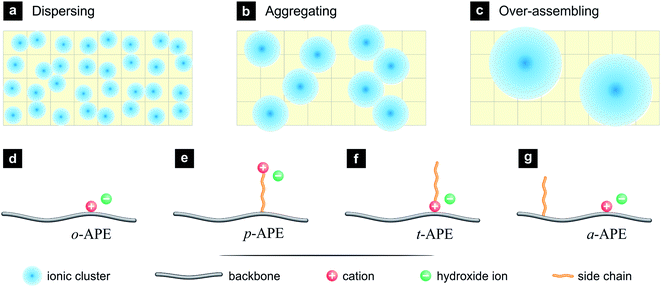
Usually, the ionic clusters (hydrated ions and surrounding water molecules) in APE are dispersed in a hydrophobic matrix (Fig. 1a), the ionic transportation is thus inhibited by the surrounding hydrophobic walls, although small ionic channels can be formed through dynamic assembly of ionic clusters. By introducing additional hydrophobic structures, it is possible to drive the ionic clusters to be aggregated, so as to generate bigger ionic clusters and to facilitate the formation of interconnected, broad ionic channels (Fig. 1b). Such an ion-aggregating structure is expected to benefit the OH− conduction, but over aggregation may result in partitioned hydrophilic domains (Fig. 1c), which will lower the probability of forming interconnected ionic channels and break the macroscopic uniformity of the APE membrane.
Among the implementation strategies for the ion-aggregating structure (Fig. 1b) is to design a hydrophobic side chain into the original structure of APE (o-APE, Fig. 1d), where the cation, typically quaternary ammonium (–NR3+), is attached closely onto the polymer backbone, and the anion (OH−) is dissociated in aqueous phase. There are three major styles to incorporate such a side chain: (i) the hydrophobic side chain is inserted between the backbone and the cation, creating a pendent-type APE (p-APE, Fig. 1e), which has been a popular structure of SPE.19,20 (ii) The hydrophobic side chain is attached onto the cation, resulting in a tadpole-type APE (t-APE, Fig. 1f).21 (iii) The hydrophobic side chain is attached onto the backbone but separated from the cation (Fig. 1g). This design is novel and denoted in the present work as a-APE.
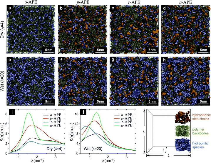
To determine which of the above designs (p-APE, t-APE, or a-APE) is more efficient in forming the ion-aggregating structure, a computational screening was carried out using the coarse-grained molecular dynamics (CGMD) simulations.22,23 Briefly, five types of beads (backbone segment (BB), side chain segment (SC), quaternary ammonia ion (QA), hydrated hydroxide ion (OH), and water cluster (WT)) were used as the building blocks to construct the APE systems (Fig. S1†) at different hydration level (λ).24 For a “dry” system (λ = 4, water is present only in OH bead OH−·3H2O), the periodic simulation box contained 800 polymer chains, with each consisting of 10 monomers (Fig. S2†); while for a “wet” system (λ = 20), additional 32![[thin space (1/6-em)]](https://www.rsc.org/images/entities/char_2009.gif) 000 WT beads (4H2O) were incorporated, corresponding to a fully hydrated state of the APE (Table S1†). The CGMD results have provided rich information about the structure of the studied APE, as demonstrated in Fig. 2. In comparison to o-APE (Fig. 2a and e), the incorporation of a hydrophobic side chain does change, to different extent, the assembling behavior of the hydrophilic species (QA, OH and WT beads) in p-APE (Fig. 2b and f), t-APE (Fig. 2c and g), and a-APE (Fig. 2d and h). For dry systems (Fig. 2a–d), whereas the OH beads are rather dispersed in o-APE (Fig. 2a) and t-APE (Fig. 2c), long-distance interconnections of ionic clusters can be observed in some part of p-APE (Fig. 2b) and in most part of a-APE (Fig. 2d). When fully hydrated, all the studied APEs now contain bigger ionic clusters (Fig. 2e–h), and interconnections between the enlarged ionic clusters can be seen in some part of o-APE (Fig. 2e), in most part of p-APE (Fig. 2f) and t-APE (Fig. 2g), and in the whole a-APE (Fig. 2h). More importantly, the ionic clusters in a-APE are relatively uniform in size and connect with each other through “broadband”, in comparison to the bottleneck-like connection between ionic clusters in other APEs.
000 WT beads (4H2O) were incorporated, corresponding to a fully hydrated state of the APE (Table S1†). The CGMD results have provided rich information about the structure of the studied APE, as demonstrated in Fig. 2. In comparison to o-APE (Fig. 2a and e), the incorporation of a hydrophobic side chain does change, to different extent, the assembling behavior of the hydrophilic species (QA, OH and WT beads) in p-APE (Fig. 2b and f), t-APE (Fig. 2c and g), and a-APE (Fig. 2d and h). For dry systems (Fig. 2a–d), whereas the OH beads are rather dispersed in o-APE (Fig. 2a) and t-APE (Fig. 2c), long-distance interconnections of ionic clusters can be observed in some part of p-APE (Fig. 2b) and in most part of a-APE (Fig. 2d). When fully hydrated, all the studied APEs now contain bigger ionic clusters (Fig. 2e–h), and interconnections between the enlarged ionic clusters can be seen in some part of o-APE (Fig. 2e), in most part of p-APE (Fig. 2f) and t-APE (Fig. 2g), and in the whole a-APE (Fig. 2h). More importantly, the ionic clusters in a-APE are relatively uniform in size and connect with each other through “broadband”, in comparison to the bottleneck-like connection between ionic clusters in other APEs.
The underlying ordered structure in the studied APEs can be revealed by structure-factor analysis25 on the CGMD results. As displayed in Fig. 2i and j, the structure factors of the hydrophilic species in dry p-APE and a-APE exhibit a clear peak (Fig. 2i), with the a-APE peak being sharper and much stronger; while in wet state (Fig. 2j), all the studied APEs have a peak in the structure-factor curve, but the a-APE peak is still the sharpest and strongest, clearly indicating that the ordered pattern created by self-assembly of ionic clusters in a-APE is particularly remarkable.
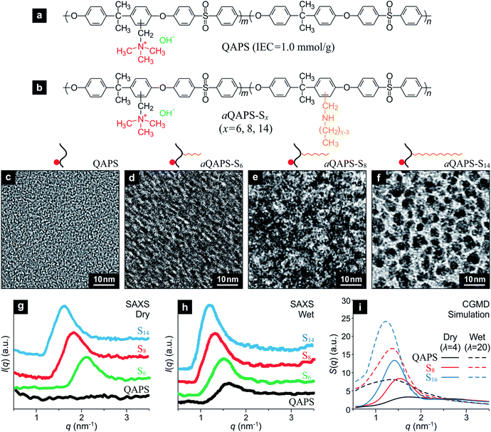
Guided by the above computational study, efforts have been devoted to the experimental implementation of the a-APE design by using quaternary ammonia polysulfone (QAPS, Fig. 3a), a well-studied APE with relatively simple sturcture,26,27 as a model system. The IEC of the QAPS-based APEs studied in the present work has been deliberately controlled at a moderate level, 1.0 mmol g−1, so as to be comparable to that of Nafion (IEC = 0.95 mmol g−1). A linear, hydrophobic side chain with adjustable length is attached onto the QAPS backbone to achieve the a-APE structure (Fig. 3b), and the resulting APEs are denoted as aQAPS-Sx where x indicates the number of non-hydrogen atoms in the side chain. A series of aQAPS-Sx have been synthesized and studied in our laboratory, and three representative products, aQAPS-S6, -S8, and -S14 (see Fig. S3 & S4† for NMR and XPS characterizations) are discussed here. From the transmission electron microscopy (TEM) images (Fig. 3c–f), one can unambiguously see the gradual enhancement in hydrophilic/hydrophobic microphase separation caused by elongating the side chain in aQAPS-Sx. Specifically, whereas no microphase separation can be observed in the pristine QAPS (Fig. 3c), the aggregation of hydrophilic species (dark spots28) is very clear in aQAPS-S8 (Fig. 3e), rather resembling to the feature predicted by CGMD simulation (Fig. 2d). In aQAPS-S14 (Fig. 3f), the assembly of hydrophilic species becomes extensive, leading to the formation of partitioned hydrophilic microdomains. The observed influence of the length of hydrophobic side chain on the morphology of aQAPS-Sx has also been verified by CGMD simulations (Fig. S5†).
Quantitative information about the size of the ionic clusters and/or their spacing can be obtained from the small-angle X-ray scattering (SAXS) pattern of the studied APEs. As revealed in Fig. 3g, there is no pattern in the SAXS signal of dry QAPS, in line with the feature of its TEM image (Fig. 3c); while for dry aQAPS-Sx (x = 6, 8, 14), SAXS peaks emerge at 2.1, 1.8, and 1.6 nm−1, corresponding to a Bragg spacing of about 3.0, 3.5, and 3.9 nm, respectively. It is evident that, even in dry aQAPS-Sx, the ionic clusters have assembled to some degree, and the longer the side chain, the more extensive the aggregation of ionic clusters. When fully hydrated, the QAPS takes on a SAXS peak at 1.6 nm−1 (Fig. 3h), while the aQAPS-Sx (x = 6, 8, 14) peaks are further enhanced and shift negatively to 1.5, 1.3, and 1.2 nm−1, respectively, suggesting the size of ionic clusters has been enlarged. Strikingly, these SAXS results turn out to be in nice agreement with the structure factors calculated from the CGMD simulations (Fig. 3i), which not only justifies the theoretical model and computational method employed in the present work, but also proves the rationality of our strategy for APE structure control.
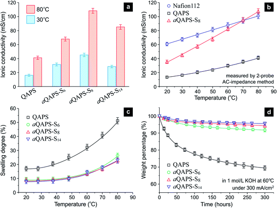
The purpose of constructing the ion-aggregating structure in APE, as stated previously, is to promote the OH− conducting efficiency. Indeed, the ionic conductivity of aQAPS-Sx is much higher than that of QAPS, with the aQAPS-S8 exhibiting the greatest improvement (Fig. 4a & S6†). At 60 °C to 80 °C (the operating temperature range of SPE-based fuel cells), the ionic conductivity of aQAPS-S8 has even reached the same level of Nafion (Fig. 4b & S7†). Since the IECs of the studied APEs are all ca. 1.0 mmol g−1, such an enhancement in the ionic conductivity can only be ascribed to the promotion in OH− mobility. Note that there were reports of APEs with high IECs (ca. 2.0 mmol g−1 or even higher), whose ionic conductivities were also comparable to that of Nafion,29,30 but the OH− conducting efficiency in those APEs were, actually, still low (Fig. S8†). For the first time, the present work unravels that the OH− conduction in APE can be made as efficient as the H+ conduction in Nafion at moderately elevated temperatures.
 | ||
| Fig. 4 The performance of the studied APE membranes. (a) Ionic conductivity comparison among QAPS, aQAPS-S6, aQAPS-S8, and aQAPS-S14. The IECs of these APEs are all ca. 1.0 mmol g−1. (b) The temperature-dependent ionic conductivity of Nafion 112, QAPS, and aQAPS-S8. See Fig. S7† for the corresponding Arrhenius plot. (c) The temperature-dependent swelling degree of the studied APE membranes. (d) The stability of the studied APE membranes, described in terms of the weight change, in 1 mol L−1 KOH solution at 60 °C under a current passage of 300 mA cm−2 (Fig. S9†). Degraded polymer fragments in KOH solution were monitored by UV-vis spectroscopy (Fig. S10†) and converted to the weight loss. | ||
Apparently, it is the ion-aggregating structure in aQAPS-S8 that promotes the OH− mobility; the resulting interconnected, broad ionic channels have served as a highway for express OH− transportation. Previous studies on block-copolymer APEs have achieved certain microphase-separation structures, which, however, were still not effective for shaping ionic highways.29,31 It is interesting to see that the OH− conductivity of aQAPS-S8 at room temperature is about 57% of the H+ conductivity of Nafion (Fig. 4b), identical to the mobility ratio between OH− and H+ in dilute aqueous solutions. This suggests that aQAPS-S8 is as superior as Nafion in terms of ionic channels. In aQAPS-S14, on the other hand, the ionic clusters seem to be over assembled, thus giving inferior OH− conductivity (Fig. 4a).
In addition to the outstanding ionic conductivity, the aQAPS-Sx membranes also exhibit a much lower swelling degree, in comparison to the QAPS with the same IEC (Fig. 4c). This is quite different from those high-IEC designs,29,30 where high ionic conductivity has to be gained at the expense of dimensional stability. The additional hydrophobic side chains in aQAPS-Sx have clearly enhanced the hydrophobic matrix in the membrane, which effectively restricts the polymer swelling and intensifies the mechanical strength (Table S1†).
The above results have manifested that the QAPS model system is very suitable for demonstrating the idea of constructing ionic highways in APE; but for practical electrochemical applications, QAPS was thought not to be stable enough. Specifically, the attachment of cationic groups would reduce the tolerance of the polysulfone backbone to the attack of OH− in alkaline environment.32,33 Unexpectedly, we find that the ion-aggregating structure, a design for improving the physical properties of APE, can also enhance the chemical stability of QAPS. To mimic electrochemical applications while avoiding unwanted complexity, we have tested the above-studied APE membranes under an electrolysis condition (namely, in a 1 mol L−1 KOH solution at 60 °C under a current passage of 300 mA cm−2, see Fig. S9† for experimental setup), and used UV-vis spectroscopy (Fig. S10†) to detect the degraded backbone fragments in KOH solution. The thus-obtained time-dependent weight loss (see ESI† for detail) is depicted in Fig. 4d. Whereas the pristine QAPS degrades gradually during a test period of 300 h, the aQAPS-Sx exhibits a distinctly enhanced stability; the weight changes of aQAPS-S8 and -S14 are rather slight after a small initial drop (probably due to the leaching out of low-molecular-weight components). The cationic functional group was also proved, based on the NMR signal of the tested membrane, to be effectively retained in aQAPS-Sx (Table S2†). Such a stability enhancement should benefit from the hydrophilic/hydrophobic separation structure, where the OH− is confined in hydrophilic domains and the polymer backbone can be well protected by the additional hydrophobic structure.
Our findings have not only furthered the fundamental understanding of the ionic channels in APE, but also provided a general strategy for the rational design of polymer electrolytes. The advanced APE demonstrated in the present work would find a wide range of potential applications, in particular in electrochemical energy conversion and storage, including fuel cells (Fig. S11†), water electrolysis,34 redox flow cells, supercapacitors, and alkaline batteries.
Acknowledgements
This work was financially supported by the National Basic Research Program (2012CB215503, 2012CB932800), the National Science Foundation of China (20933004, 21125312), the National Hi-Tech R&D Program (2011AA050705), the Doctoral Fund of Ministry of Education of China (20110141130002), the Program for Changjiang Scholars and Innovative Research Team in University (IRT1030).References and notes
- B. E. Logan and M. Elimelech, Membrane-based processes for sustainable power generation using water, Nature, 2012, 488, 313–319 CrossRef CAS PubMed.
- B. C. H. Steele and A. Heinzel, Materials for fuel-cell technologies, Nature, 2001, 414, 345–352 CrossRef CAS PubMed.
- K. Schmidt-Rohr and Q. Chen, Parallel cylindrical water nanochannels in Nafion fuel-cell membranes, Nat. Mater., 2008, 7, 75–83 CrossRef CAS PubMed.
- K. A. Mauritz and R. B. Moore, State of understanding of Nafion, Chem. Rev., 2004, 104, 4535–4585 CrossRef CAS PubMed.
- M. K. Debe, Electrocatalyst approaches and challenges for automotive fuel cells, Nature, 2012, 486, 43–51 CrossRef CAS PubMed.
- S. Lu, J. Pan, A. Huang, L. Zhuang and J. Lu, Alkaline polymer electrolyte fuel cells completely free from noble metal catalysts, Proc. Natl. Acad. Sci. U. S. A., 2008, 105, 20611–20614 CrossRef CAS.
- J. R. Varcoe and R. C. T. Slade, Prospects for alkaline anion-exchange membranes in low temperature fuel cells, Fuel Cells, 2005, 5, 187–200 CrossRef CAS.
- K. Asazawa et al., A platinum-free zero-carbon-emission easy fuelling direct hydrazine fuel cell for vehicles, Angew. Chem., Int. Ed., 2007, 46, 8024–8027 CrossRef PubMed.
- A solid polymer version of alkaline electrolyte can, on the one hand, minimize the gap between two electrodes (usually only in tens of microns), which makes the electrochemical device more compact in size and higher in energy conversion efficiency, and, on the other hand, eliminate the problems caused by liquid electrolyte leakage, such as the waterproof breaking in gas-diffusion electrodes caused by carbonate precipitation.
- M. E. Tuckerman, D. Marx and M. Parrinello, The nature and transport mechanism of hydrated hydroxide ions in aqueous solution, Nature, 2002, 417, 925–929 CrossRef CAS PubMed.
- M. R. Hibbs et al., Transport properties of hydroxide and proton conducting membranes, Chem. Mater., 2008, 20, 2566–2573 CrossRef.
- P. W. Atkins, Atkins' Physical Chemistry, Oxford Univ. Press, edn 6, 1998, ch. 24, p. 738 Search PubMed.
- J. Pan, C. Chen, L. Zhuang and J. Lu, Designing advanced alkaline polymer electrolytes for fuel cell applications, Acc. Chem. Res., 2012, 45, 473–481 CrossRef CAS PubMed.
- T. J. Peckham and S. Holdcroft, Structure-morphology-property relationships of non-perfluorinated proton-conducting membranes, Adv. Mater., 2010, 22, 4667–4690 CrossRef CAS PubMed.
- S. Gu, R. Cai and Y. Yan, Self-crosslinking for dimensionally stable and solvent-resistant quaternary phosphonium based hydroxide exchange membranes, Chem. Commun., 2011, 47, 2856–2858 RSC.
- J. Pan, Y. Li, L. Zhuang and J. Lu, Self-crosslinked alkaline polymer electrolyte exceptionally stable at 90 °C, Chem. Commun., 2010, 46, 8597–8599 RSC.
- J. Zhou, M. Unlu, J. A. Vega and P. A. Kohl, Anionic polysulfone ionomers and membranes containing fluorenyl groups for anionic fuel cells, J. Power Sources, 2009, 190, 285–292 CrossRef CAS.
- Although crosslinking is a usual means to restrict the swelling of SPE membranes of high IEC, it is at the expense of ionic conductivity and membrane flexibility.
- J. Ran, L. Wu, X. Lin, L. Jiang and T. Xu, Synthesis of soluble copolymers bearing ionic graft for alkaline anion exchange membrane, RSC Adv., 2012, 2, 4250–4257 RSC.
- M. J. Jung, C. G. Arges and V. Ramani, A perfluorinated anion exchange membrane with a 1,4-dimethylpiperazinium cation, J. Mater. Chem., 2011, 21, 6158–6160 RSC.
- N. Li, T. Yan, Z. Li, T. Thurn-Albrecht and W. H. Binder, Comb-shaped polymers to enhance hydroxide transport in anion exchange membranes, Energy Environ. Sci., 2012, 5, 7888–7892 CAS.
- D. Wu, S. J. Paddison and J. A. Elliott, A comparative study of the hydrated morphologies of perfluorosulfonic acid fuel cell membranes with mesoscopic simulations, Energy Environ. Sci., 2008, 1, 284–293 CAS.
- S. J. Marrink, A. H. de Vries and A. E. Mark, Coarse grained model for semiquantitative lipid simulations, J. Phys. Chem. B, 2004, 108, 750–760 CrossRef CAS.
- The hydration level (λ) represents the amount ratio between water molecule and hydroxide ion in APE. See Table S1 and ESI for details.†.
- The structure factor S(q) describes the radiation scattering pattern of a material in reciprocal radial coordinate (q), which can be calculated from a given material structure or observed experimentally using X-ray or neutron scattering. See ESI for computational details.†.
- C. G. Arges, J. Parrondo, G. Johnson, A. Nadhan and V. Ramani, Assessing the influence of different cation chemistries on ionic conductivity and alkaline stability of anion exchange membranes, J. Mater. Chem., 2012, 22, 3733–3744 RSC.
- J. Pan et al., High-performance alkaline polymer electrolyte for fuel cell applications, Adv. Funct. Mater., 2010, 20, 312–319 CrossRef.
- The APEs have been dyed with I− prior to TEM observation, such that the hydrophilic microphase can be visualised as dark spots due to the much higher electron density of I−.
- M. Tanaka et al., Anion conductive block poly(arylene ether)s: Synthesis, properties, and application in alkaline fuel cells, J. Am. Chem. Soc., 2011, 133, 10646–10654 CrossRef PubMed.
- N. J. Robertson et al., Tunable high performance cross-linked alkaline anion exchange membranes for fuel cell applications, J. Am. Chem. Soc., 2010, 133, 3400–3404 CrossRef PubMed.
- K. M. Lee, R. Wycisk, M. Litt and P. N. Pintauro, Alkaline fuel cell membranes from xylylene block ionenes, J. Membr. Sci., 2011, 383, 254–261 CrossRef CAS.
- S. A. Nuñez and M. A. Hickner, Quantitative 1H NMR analysis of chemical stabilities in anion-exchange membranes, ACS Macro Lett., 2013, 2, 49–52 CrossRef.
- C. G. Arges and V. Ramani, Two-dimensional NMR spectroscopy reveals cation-triggered backbone degradation in polysulfone-based anion exchange membranes, Proc. Natl. Acad. Sci. U. S. A., 2013, 110, 2490–2495 CrossRef CAS PubMed.
- L. Xiao et al., First implementation of alkaline polymer electrolyte water electrolysis working only with pure water, Energy Environ. Sci., 2012, 5, 7869–7871 Search PubMed.
Footnotes |
| † Electronic supplementary information (ESI) available: Fig. S1–S11, Table S1 and S2, and methods. See DOI: 10.1039/c3ee43275k |
| ‡ These authors contributed equally to this work. |
| This journal is © The Royal Society of Chemistry 2014 |


