Structure–property relationships of oligothiophene–isoindigo polymers for efficient bulk-heterojunction solar cells†
Received
5th September 2013
, Accepted 16th October 2013
First published on 17th October 2013
Abstract
A series of alternating oligothiophene (nT)–isoindigo (I) copolymers (PnTI) were synthesized to investigate the influence of the oligothiophene block length on the photovoltaic (PV) properties of PnTI:PCBM bulk-heterojunction blends. Our study indicates that the number of thiophene rings (n) in the repeating unit alters both polymer crystallinity and polymer–fullerene interfacial energetics, which results in a decreasing open-circuit voltage (Voc) of the solar cells with increasing n. The short-circuit current density (Jsc) of P1TI:PCBM devices is limited by the absence of a significant driving force for electron transfer. Instead, blends based on P5TI and P6TI feature large polymer domains, which limit charge generation and thus Jsc. The best PV performance with a power conversion efficiency of up to 6.9% was achieved with devices based on P3TI, where a combination of a favorable morphology and an optimal interfacial energy level offset ensures efficient exciton separation and charge generation. The structure–property relationship demonstrated in this work would be a valuable guideline for the design of high performance polymers with small energy losses during the charge generation process, allowing for the fabrication of efficient solar cells that combine a minimal loss in Voc with a high Jsc.
Broader context
Polymer solar cells (PSCs) have emerged as promising candidates for low-cost, environmentally friendly energy conversion. However, a low power conversion efficiency (PCE) is still the main bottleneck for their commercial applications. In order to further improve their PCE, a detailed understanding of the underlying structure–property relationships that govern these materials is crucial. In this work, a series of alternating oligothiophene (nT)–isoindigo (I) copolymers (PnTI) were synthesized to investigate the influence of the oligothiophene block length on the photovoltaic (PV) properties of PnTI:PCBM bulk-heterojunction blends. The driving force for the PSCs can be fine-tuned in a small range of 0–0.1 eV by changing the conjugated length of the oligothiophene block. This is a valuable guideline for polymer design to achieve high-efficiency PSCs with optimum photovoltage and photocurrent.
|
1. Introduction
The performance of polymer solar cells (PSCs) based on the bulk-heterojunction (BHJ)1 concept is improving rapidly due to extensive research efforts.2,3 When donor–acceptor (D–A) conjugated polymers, which contain alternating electron-rich and -deficient units along the polymer main chain,4,5 are blended with fullerene derivatives, power conversion efficiencies (PCEs) of over 7–9% can be achieved.6–8 In order to realize a high PCE, the short-circuit current density (Jsc), fill factor (FF) and open-circuit voltage (Voc) have to be maximized at the same time. A crucial factor that determines the photovoltaic (PV) performance is the difference between the energy of the excited polymer exciton (ED*) and the energy of the charge-transfer exciton (ECT), or so-called driving force.9–11 A large driving force results in a low Voc,9,11,12 while an insufficient driving force can obstruct exciton dissociation and charge carrier generation, which reduces Jsc.9–11 To further enhance the PV performance of PSCs, novel low band gap polymers with an optimized driving force need to be developed.13,14 However, there is a lack of systematic studies that provide detailed synthesis guidelines for fine-tuning this driving force, especially in a small range of 0–0.1 eV.
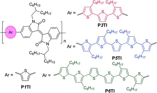
Isoindigo-containing D–A copolymers attract significant attention in the field of organic electronics owing to their high charge-carrier mobility.15,16 Already widely used in the dye industry, these segments were first utilized in the photovoltaic field to build D–A small molecules in 2010,17 followed by isoindigo-containing copolymers.18–22 The strong electron-withdrawing nature of the isoindigo group extends the absorption spectra of copolymers to the near infrared (NIR) region.19–22 We previously reported devices based on PTI-1 (renamed as P1TI for clarity in this work) (Scheme 1) with thiophene as the electron-rich unit and isoindigo as the electron-deficient (in the ground state) unit. PSCs based on this material had a PCE of 4.5%, with a high Voc of 0.91 V but a low Jsc of 9.1 mA cm−2 due to an insufficient driving force.9,23 Instead, when terthiophene was used as the electron-rich unit, the PCE of P3TI-based PSCs was improved to 6.3% due to a large improvement in Jsc to 13.1 mA cm−2, which more than compensated for a decrease in Voc to 0.70 V.9,21 Evidently, despite the similar chemical structures a very different photovoltaic performance is obtained, which necessitates an in-depth investigation of relevant structure–property relationships of these oligothiophene–isoindigo polymers.
 |
| | Scheme 1 The chemical structures of oligothiophene–isoindigo copolymers PnTI. | |
Thus, we here expand our series by synthesizing polymers with longer oligothiophene groups and carefully analyze the nanostructure and electronic properties of PnTI polymers as well as PnTI:PCBM blends using a suite of complementary characterization techniques. Our experimental results indicate that the number of thiophene rings can not only affect the energy losses during electron transfer, but also strongly influence the charge generation process due to significant variations in polymer crystallinity and active layer morphology. A sufficient driving force with minimal energy loss and optimum morphology was achieved with P3TI-based PSCs, which show a PCE of up to 6.9%.
2. Results and discussion
2.1. Synthesis and characterizations of the polymers
PnTI polymers were synthesized via the Stille coupling reaction. As depicted in Scheme 1, the number of thiophene rings ranges from 1, 3, 5 to 6. P1TI and P3TI were synthesized according to our previous reports.20,21 Details of the synthesis of P5TI and P6TI are described in the ESI.† To ensure good solubility, octyl side chains were attached on appropriate thiophene rings. The side-chain grafting positions were chosen with the aim to avoid obvious steric hindrance. Nevertheless, attempts to synthesize P2TI and P4TI failed due to their poor solubility. The number-average molecular weights (Mn) and polydispersity index (PDI) for the PnTI series are listed in Table 1. All polymers are of sufficiently high molecular weight (Mn > 60 kg mol−1) to avoid a strong influence of chain length on the PV performance.24,25 However, we note that the Mn ∼ 100 kg mol−1 of the P3TI batch used in this study is slightly higher than the Mn ∼ 43 kg mol−1 of the batch in our previous report,21 which may explain the slight improvement in PCE from 6.3 to 6.9%.
Table 1 Molecular weights, optical band gap and FET mobilities of PnTI
| Polymer |
M
n (kg mol−1) |
PDI |
Polymer films |
As spin-coated |
Annealed at 170 °C |
|
E
optg
(eV) |
μ
h (cm2 V−1 s−1) |
μ
e (cm2 V−1 s−1) |
μ
h (cm2 V−1 s−1) |
μ
e (cm2 V−1 s−1) |
|
The error bar is estimated from the onset of the optical band gap (∼800 ± 10 nm).
|
| P1TI |
60 |
2.2 |
1.55 ± 0.02 |
(8.9 ± 1.5) × 10−4 |
(1.2 ± 0.2) × 10−3 |
(1.0 ± 0.4) × 10−3 |
(8.1 ± 0.6) × 10−3 |
| P3TI |
100 |
3.3 |
1.50 ± 0.02 |
(1.8 ± 0.2) × 10−3 |
(5.1 ± 1.1) × 10−4 |
(3.0 ± 0.1) × 10−2 |
(5.0 ± 1.1) × 10−3 |
| P5TI |
149 |
3.2 |
1.53 ± 0.02 |
(8.6 ± 0.3) × 10−4 |
(6.6 ± 2.2) × 10−5 |
(3.6 ± 0.2) × 10−3 |
(5.3 ± 0.2) × 10−4 |
| P6TI |
67 |
2.6 |
1.52 ± 0.02 |
(1.7 ± 0.3) × 10−3 |
(8.0 ± 4.0) × 10−5 |
(7.4 ± 0.2) × 10−3 |
(2.3 ± 1.1) × 10−4 |
2.2. Optical properties of PnTI and PnTI:PCBM
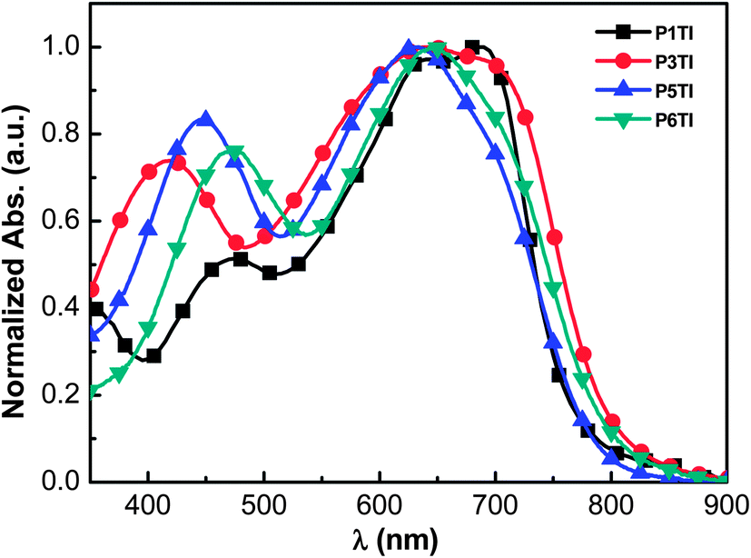
The normalized UV-Vis absorption spectra of the four polymers in the solid state are shown in Fig. 1. Thin films of a similar thickness were spin-coated from o-dichlorobenzene (o-DCB) solutions. As shown in Fig. 1, all polymers show relatively broad absorption spectra with onsets around 800 nm and two absorption peaks in the region of 400–800 nm. The peak in the high-energy region (400–500 nm) are thought to arise from the π–π* transition on the donor segments (oligothiophene group), while the peak in the low-energy region can be attributed to an intramolecular charge transfer (ICT) transition between the donor and acceptor units.26–28 To compare the absolute absorption coefficients of the polymers, variable-angle spectroscopic ellipsometry (VASE) was employed (see Fig. S1(b)†). All PnTI polymers strongly absorb in the 550–700 nm region with an absorption coefficient of ∼1.2 × 105 cm−1. The absorption bands in the high-energy region (400–500 nm) are enhanced and red-shift with increasing n. This red-shift can be explained by the increase in the conjugation length of the oligothiophene block, which leads to a smaller π–π* band gap.27,28
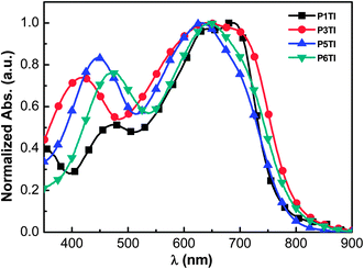 |
| | Fig. 1 Normalized UV-Vis absorption spectra of PnTI films spin-coated from o-DCB solution. | |
The absorption coefficients of PnTI:PCBM blends were determined by VASE (Fig. 2(a)). We used PC71BM as the acceptor for all polymers but P1TI, which was blended with PC61BM, because this combination resulted in a better PV performance (cf. section “Photovoltaic performance” below).23 The blends of P3TI, P5TI and P6TI with PC71BM show much stronger absorption in the high-energy region (400–500 nm) compared to those with P1TI:PC61BM, which originates from the high absorption coefficient of PC71BM in this region. Based on the assumption that all the photons absorbed by the blends can be converted into photocurrent, one can simulate the maximum short-circuit photocurrent density (Jsc-max) that can be achieved. Jsc-max calculated by the transfer matrix model (TMM)29 is plotted in Fig. 2(b) as a function of film thickness. For all blends, two photocurrent maxima are found for a thickness of 50–300 nm. The first photocurrent maximum is located at a thickness of ∼100 nm, which we consider to be the optimized thickness since charge extraction in much thicker active layers can become problematic. For P3TI, P5TI and P6TI-based blends we find a similar value of Jsc-max ∼ 16 mA cm−2 at the first photocurrent maximum, which indicates a comparable ability of these systems to capture photons. The lower Jsc-max ∼ 13.6 mA cm−2 of P1TI:PC61BM can be explained by the weak absorption of PC61BM in combination with a narrower absorption spectrum of P1TI (cf.Fig. 2(a)).
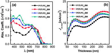 |
| | Fig. 2 (a) The absorption coefficient (α) spectra of PnTI:PCBM blends and (b) calculated Jsc-max as a function of active layer thickness: P1TI:PC61BM, P3TI:PC71BM, P5TI:PC71BM and P6TI:PC71BM. | |
2.3. Energy levels of PnTI
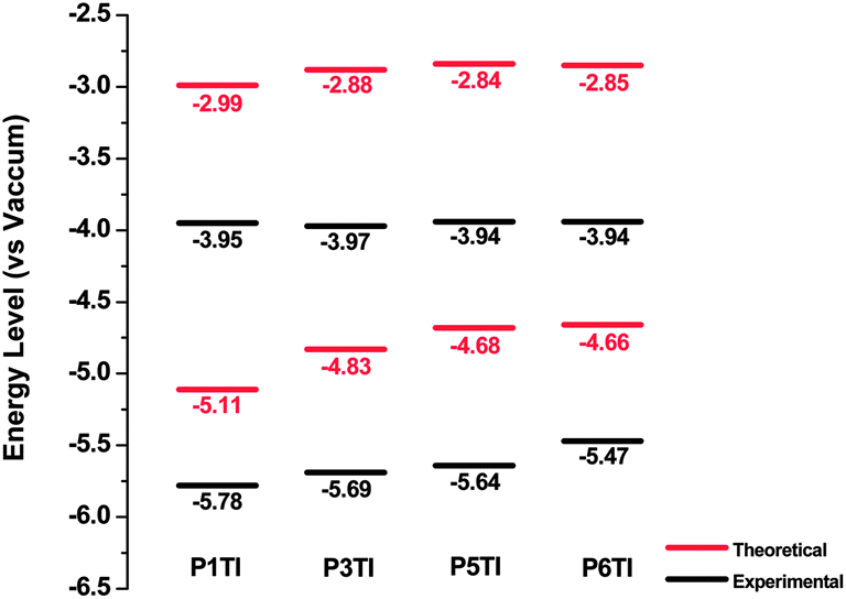
Highest occupied molecular orbital (HOMO) and lowest unoccupied molecular orbital (LUMO) levels of PnTI were deduced experimentally from cyclic voltammetry (CV) on thin films from chloroform as well as theoretically from density functional theory (DFT) simulations (Fig. 3). The HOMO and LUMO positions were derived from the onset of oxidation (Eox) and reduction potentials (Ered) obtained from CV curves according to the equations HOMO = −(Eox + 5.13) eV and LUMO = −(Ered + 5.13) eV.30 All potentials were calibrated with the standard ferrocene/ferrocenium redox couple.31 DFT calculations were performed using Gaussian 09 with a hybrid B3LYP correlation functional32,33 and a split valence 6-31G* basis set.34 In order to reduce the computing time, calculations were performed for trimers containing three repeating units with methyl groups instead of long octyl side chains.
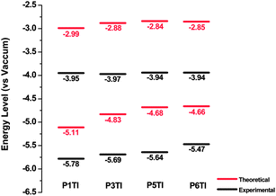 |
| | Fig. 3 Theoretical and experimental energy levels of PnTI from cyclic voltammetry measurements and DFT calculations. | |
Our DFT calculations show that the trimer, which corresponds to P1TI, has a slightly lower LUMO level compared to the other three trimers. However, the LUMO levels as measured by CV are nearly identical. This is consistent with a previous report by Blouin et al., which demonstrates that LUMO levels are mainly determined by electron-deficient units but are only slightly influenced by electron-rich units.35 On the other hand, differences can be found in the HOMO levels as revealed by both CV measurements and DFT calculations, which is likely to affect the Voc of PnTI-based PSCs.36 Moreover, our DFT calculations suggest that all modeled trimers have largely planar backbones, favorable for π-stacking, as depicted by the side view of the optimal molecular conformations at 0 K in the gas phase (Fig. S3†).
2.4. Photovoltaic performance
The PSCs studied in this work are prepared in the conventional device geometry (ITO/PEDOT:PSS/active layer/LiF/Al). The PV performance of each PnTI:PCBM active layer was optimized by choosing different acceptors (PC61BM/PC71BM), processing solvents, and D–A stoichiometry. The optimized D![[thin space (1/6-em)]](https://www.rsc.org/images/entities/char_2009.gif) :A weight ratio for all the polymers is 2:3 and the processing solvents are o-DCB containing 2.5% (by volume) diiodooctane (DIO). DIO was added because according to a number of previous reports the morphology of the active layer can be improved.37,38 In this work we compare the results obtained from fully optimized PSCs. Therefore, PC61BM is used for P1TI-based PSCs and PC71BM for devices based on the other three PnTI polymers.20,21,23 According to the optical simulation results shown in Fig. 2(b), the optimal active layer thickness is around 100 nm for all PnTI:PCBM blends.
:A weight ratio for all the polymers is 2:3 and the processing solvents are o-DCB containing 2.5% (by volume) diiodooctane (DIO). DIO was added because according to a number of previous reports the morphology of the active layer can be improved.37,38 In this work we compare the results obtained from fully optimized PSCs. Therefore, PC61BM is used for P1TI-based PSCs and PC71BM for devices based on the other three PnTI polymers.20,21,23 According to the optical simulation results shown in Fig. 2(b), the optimal active layer thickness is around 100 nm for all PnTI:PCBM blends.
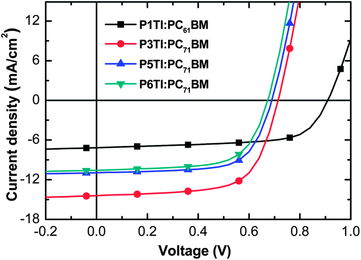
The current density–voltage (J–V) curves from optimized PSCs are plotted in Fig. 4 and the corresponding PV parameters are listed in Table 2. Statistical deviations of the PV parameters for PnTI:PCBM solar cells are given in Fig. S4.† The device with P1TI:PC61BM as the active layer has the lowest PCE of 4.3%, whereas the P3TI:PC71BM device exhibits the highest PCE of 6.9%. The slightly higher efficiency compared to our previous report (6.3%) can be ascribed to the higher molecular weight of P3TI used in this work.39,40 Lower PCEs are obtained for PSCs with P5TI:PC71BM and P6TI:PC71BM. The Voc of the devices decreases from 0.91 to 0.65 V when n increases from 1 to 6, which is consistent with the observed trend in HOMO levels (cf.Fig. 3). We obtain the highest Jsc for a champion PSC based on P3TI:PC71BM, which outperforms the devices based on PnTI with both a shorter and a longer oligothiophene block. The Jsc ∼ 14.63 mA cm−2 of this device is close to the modeled Jsc-max ∼ 16.8 mA cm−2. In contrast, optimum PSCs based on the other three polymers display a larger difference between Jsc and modeled Jsc-max. We can identify three possible reasons for the apparent loss in generated current-density: (i) the polymer charge-carrier mobility is too low, (ii) the driving force for charge separation is insufficient, and (iii) the morphology of the active layers is non-optimal. In the following, we investigate these three arguments in detail with the aim to identify the origin for the observed PV performance.
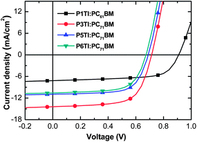 |
| | Fig. 4
J–V curves of devices based on P1TI:PC61BM, P3TI:PC71BM, P5TI:PC71BM and P6TI:PC71BM. | |
Table 2 PV parameters, active layer thickness, EQEEL and driving force of optimized PSCs based on PnTI:PCBM blends
| Active layer |
J
sc (mA cm−2) |
FF |
V
oc (V) |
PCE (%) |
EQEEL |
V
radoc (eV) |
E
CT (eV) |
E
D*
(eV) |
Driving forceb (eV) |
|
The error bar for ED* is from the energy of the optical band gap of PnTI (ED* = Eoptg).
The error bar for the driving force is from ED* (driving force = ED* − ECT).
|
| P1TI:PC61BM |
7.16 |
0.66 |
0.91 |
4.30 |
7.0 × 10⁻⁷ |
1.27 |
1.55 |
1.55 ± 0.02 |
0.00 ± 0.02 |
| P3TI:PC71BM |
14.63 |
0.66 |
0.72 |
6.90 |
1.5 × 10⁻⁸ |
1.17 |
1.45 |
1.50 ± 0.02 |
0.05 ± 0.02 |
| P5TI:PC71BM |
11.28 |
0.67 |
0.69 |
5.26 |
6.0 × 10⁻⁹ |
1.15 |
1.43 |
1.53 ± 0.02 |
0.10 ± 0.02 |
| P6TI:PC71BM |
10.51 |
0.66 |
0.65 |
4.65 |
4.0 × 10⁻⁹ |
1.12 |
1.40 |
1.52 ± 0.02 |
0.12 ± 0.02 |
2.5. Mobilities of PnTI from field effect transistor (FET) measurements
Optimized PSCs based on PnTI:PCBM feature similar and high FFs ∼ 0.66, which suggests that the difference in Jsc of these devices is not limited by insufficient charge carrier mobilities (similar active layer thicknesses of about 100 nm are used for all the devices).41,42 To gain further insight, we measured the hole and electron mobilities of PnTI polymers in bottom-gate, bottom-contact field-effect transistors (FETs). Active layers were spin-coated from chloroform and annealed for one hour at 170 °C according to Mei et al., who found that this treatment optimizes the FET mobilities of thiophene-isoindigo copolymers.16 As summarized in Table 1, all polymers displayed a comparable hole mobility μh ∼ 10−3 cm2 V−1 s−1 after spin-coating from chloroform. The hole mobility of all four polymers increased after annealing at 170 °C, which is likely due to improved molecular packing (cf. discussion on crystalline order below). The highest μh ∼ 3 × 10⁻² cm2 V−1 s−1 was obtained for P3TI, although its high mobility does not seem to be the primary factor behind the high Jsc of optimized PSCs based on the same polymer. Interestingly, all PnTI polymers display ambipolar behavior. The electron mobility μe decreases with the number of thiophene rings from μe ∼ 8 × 10⁻³ cm2 V−1 s−1 for P1TI to μe ∼ 2 × 10⁻⁴ cm2 V−1 s−1 for P6TI.43 As shown in Fig. S3,† HOMO and LUMO orbitals of P1TI can delocalize over the whole backbone of the modeled trimer, which indicates that efficient intrachain transport of electrons as well as holes is feasible. The larger overlap of the HOMO and LUMO orbitals of P1TI can also explain its higher absorption coefficient (Fig. S3 and S1(b)†).43,44
2.6. Energy of charge transfer state and device Voc
The energy of the charge transfer (CT) state (ECT) is considered to be the effective band gap of a D–A blend and determines the Voc of a BHJ organic solar cell.11,45–48 Generally, ECT depends on the difference between the LUMO level of the acceptor and the HOMO level of the donor, with significant contributions from D–A material interactions. It can be deduced from electroluminescence (EL) measurements49 or from the external quantum efficiency (EQE) measured in the low energy sub-optical gap region with highly sensitive techniques, such as Fourier-transform photocurrent spectroscopy (FTPS).50 However, when ECT of the BHJ blend is very close to the energy of the polymer exciton (ED*), such as for the PnTI:PCBM systems, it becomes more difficult to distinguish CT absorption and emission bands from the local donor excitations. As shown in Fig. S5,† a broadening of the absorption tail but no distinct CT absorption bands can be detected using FTPS-EQE spectra, indicating that the CT absorption is masked by the absorption of the neat PnTI material. However, the red-shifted EL of the blends as compared to that of the pure polymers indicates that low energy CT states are present.
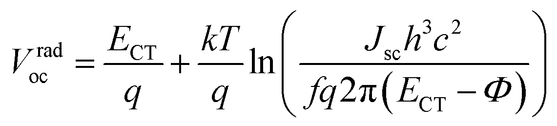
Since the CT band and local donor excitations overlap, we estimate ECTvia the Voc obtained for the blend by using eqn (1) and (2).51–53Vradoc is the open-circuit voltage when radiative recombination is the sole loss mechanism.
| | 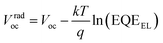 | (1) |
Vradoc for all P
nTI:PCBM-based PSCs is obtained, which permitted us to deduce
ECT from
eqn (2):
| | 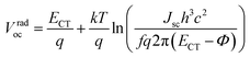 | (2) |
here,
k is the Boltzmann's constant,
q is the elementary charge,
T is the absolute temperature, EQE
EL is the radiative recombination efficiency, which is measured as the external quantum efficiency of electroluminescence as listed in
Table 2,
h is the Planck constant,
f is a prefactor, which is proportional to the electronic coupling matrix element squared and the interfacial area, and
Φ is the reorganization energy. Provided that the electronic coupling of donor–acceptor
f is within the same order of magnitude for all P
nTI:PCBM blends, the loss of
Voc due to recombination depends weakly on
ECT. As a result, the second term in
eqn (2) can be regarded as a constant and we obtain
eqn (3):
| | 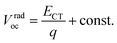 | (3) |
Thus, ECT of the PnTI:PCBM blends can be estimated from Vradoc (Table 2). The constant can be deduced from the fact that the ECT of the P1TI:PCBM system is equal to ED* since the driving force (ED* − ECT) is close to ∼0.0 eV, as indicated by the absence of any redshift in the blend EL spectrum as compared to pure P1TI.9 As summarized in Table 2, ECT of the PnTI:PCBM blends decreases with the number of thiophene rings in the repeating unit, while losses due to a non-radiative recombination increase with the number of thiophene rings. Both effects contribute to the reduction in Voc with increasing n.
2.7. Driving force and exciton dissociation
Once ECT is known, the driving force for exciton dissociation can be estimated by the difference between ED* and ECT (ED* − ECT).9,11 Here, ED* is equal to the optical band gap of the polymers. For the solar cell based on P3TI:PC71BM an internal quantum efficiency (IQE) of ∼90% can be obtained despite a low driving force of only ∼0.1 eV. In the present work, we find that the driving force ED* − ECT of PnTI:PCBM based PSCs increases with the number of thiophene rings in the repeating unit as listed in Table 2. The data are consistent with the comparison of EL spectra of the PSCs fabricated from pure PnTI polymers and PnTI:PCBM blends. The EL of blend-based devices is red-shifted due to the presence of CT emission bands, whereas the EL of the devices based on pure PnTI arises from polymer exciton emission only (Fig. S6†).49 Thus, the offset between emission peaks of the pure polymer and the corresponding blend is proportional to the driving force. As shown in Fig. S6,† this offset increases with n.
However, despite the increased driving force of P5TI:PC71BM and P6TI:PC71BM blends the overall exciton dissociation is insufficient, as indicated by the photoluminescence (PL) measurements (Fig. S7†). PL quenching efficiencies (ΔPL) were calculated according to eqn (4):
| | 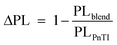 | (4) |
where PL
blend and PL
PnTI are the integrated relative PL counts of P
nTI:PCBM blends and pure P
nTI, respectively. We estimate the largest ΔPL ∼ 90% for the P3TI system, which is in strong contrast to a significantly lower value of ∼70%, ∼80% and ∼65% for the P1TI, P5TI and P6TI system, respectively. This observation suggests that exciton dissociation is the most efficient in P3TI:PC
71BM blends, which is consistent with the high
Jsc. To investigate whether the low PL quenching efficiency of the remaining blends is due to insufficient exciton diffusion or interfacial exciton dissociation, we measured field-dependent PL quenching under the application of a negative bias voltage.
54 The relative integrated PL counts as a function of applied negative voltage are plotted in
Fig. 5. As expected, the PL quenching behavior of all pure polymer devices does not vary with the applied field. For the examined P1TI:PC
61BM device we observe that a substantial amount of PL emission is quenched when high negative voltages are applied. We conclude that the low driving force prevents excitons that have reached the P1TI:PC
61BM interface from eventually dissociating into free charge carriers. For such a low driving force, back electron transfer of the system from CT state to D* state is likely and competes with CT state dissociation into free carriers. Such a singlet exciton regeneration has been observed previously.
55 However, once an external driving force is provided by a high electric field, the dissociation of CT states is facilitated and D* regeneration and subsequent emission are prevented. This results in a much higher quenching efficiency ΔPL of ∼ 85% for a bias voltage of −8 V. In significant contrast, P3TI:PC
71BM, P5TI:PC
71BM and P6TI:PC
71BM based devices display a constant quenching efficiency with increasing reverse voltage, which indicates that the observed inefficient exciton dissociation is not caused by a lack of driving force. We therefore ascribe the reason for the low quenching efficiency to the existence of large polymer domains in the blends, which prevent excitons from reaching the D–A interface before exciton recombination occurs. In the next section we use a combination of IQE, transmission electron microscopy (TEM) and grazing-incidence wide-angle X-ray scattering (GIWAXS) measurements to verify this argument.
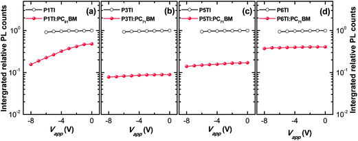 |
| | Fig. 5 Integrated relative PL counts obtained from devices based on pure PnTI (open circles) and PnTI:PCBM blends (solid circles) under a reverse bias voltage for (a) P1TI, (b) P3TI, (c) P5TI and (d) P6TI system. | |
2.8. Quantum efficiency and morphology
IQE is a suitable tool to separate absorption losses from charge generation and recombination losses under short-circuit conditions. IQE calculations were conducted based on EQE measurements, using eqn (5):| | 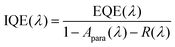 | (5) |
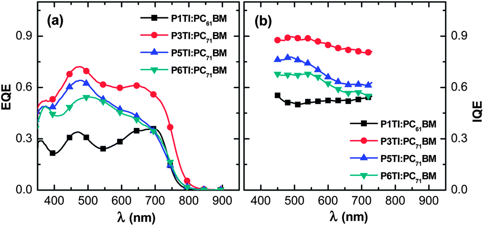
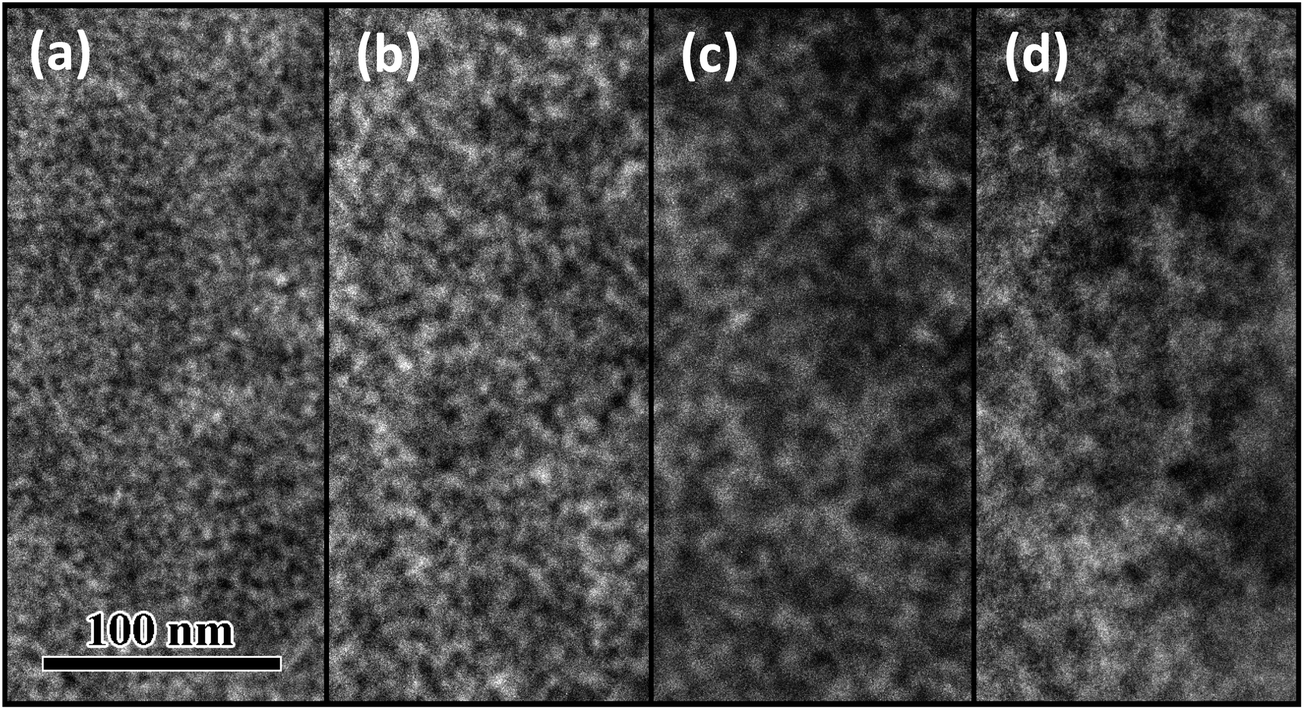
where EQE(λ) and R(λ) are the measured EQE and reflectance of the PSCs, respectively, and Apara(λ) is the parasitic electrode absorption deduced from TMM.29,56 We find that the highest IQE for PSCs is based on P3TI:PC71BM, while P1TI:PC61BM devices display the lowest IQE (Fig. 6), since exciton dissociation is limited due to the low driving force. It is worth noting that the IQE of PSCs based on P5TI:PC71BM and P6TI:PC71BM is not only lower than that of the P3TI:PC71BM devices, but also wavelength dependent. Burkhard et al. have reported that the IQE of P3HT:PC61BM based PSCs is lower at wavelengths, at which PC61BM absorbs. This was rationalized by the existence of large PC61BM domains in combination with a short exciton diffusion length in PC61BM.57 Instead, for the here investigated blends we observe that the IQE is higher at wavelengths, at which PC71BM strongly absorbs. This observation is consistent with the presence of large polymer domains in P5TI:PC71BM and P6TI:PC71BM blends and implies the absence of large PC71BM domains. This argument is consistent with the absence of PL from PCBM (Fig. S7†), which indicates that all PCBM excitons are converted to D* excitons or dissociate into free charge carriers. Furthermore, TEM images suggest that the nanostructure coarsens with increasing length of the oligothiophene block (Fig. 7), which is consistent with our PL quenching experiments.
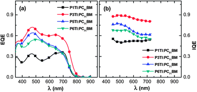 |
| | Fig. 6 (a) EQE and (b) IQE spectra for P1TI:PC61BM, P3TI:PC71BM, P5TI:PC71BM and P6TI:PC71BM based PSCs. | |
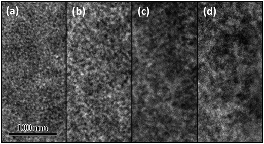 |
| | Fig. 7 TEM images of (a) P1TI:PC61BM, (b) P3TI:PC71BM, (c) P5TI:PC71BM and (d) P6TI:PC71BM. All active layers are prepared from o-DCB:DIO (2.5% by volume) solutions. | |
To investigate the reason for the existence of large polymer domains in PnTI:PCBM blends, we studied the thermal behavior of PnTI polymers with differential scanning calorimetry (DSC). Recorded heating thermograms display a clear melting endotherm at elevated temperature, which suggests that all four polymers are semi-crystalline (Fig. S8† and Table 3). The peak melting temperature decreases from Tm ∼ 321 °C for P1TI to Tm ∼ 289 °C for P3TI and Tm ∼ 226 °C for P5TI, which we ascribe to the increasing number of alkyl-substituted thiophene rings. In contrast, the addition of a second unsubstituted thiophene ring to the backbone again raises the melting temperature of P6TI to Tm ∼ 272 °C. Moreover, we note that the observed melting transitions of P1TI and P3TI feature the highest enthalpy of fusion ΔHf ∼ 24 J g−1, which highlights the ability of these polymers to order.
Table 3 Structural parameters of PnTI spin-coated from chloroform and annealed for one hour at 170 °C
|
|
T
m (°C) |
T
c (°C) |
ΔHf (J g−1) |
d
100 (Å) |
D
100 (Å) |
d
010 (Å) |
D
010 (Å) |
010 texture (°) |
| P1TI |
321 |
— |
24 |
20 |
67 |
3.7 |
22 |
43 |
| P3TI |
289 |
220 |
24 |
21 |
209 |
3.7 |
29 |
33 |
| P5TI |
226 |
177 |
12 |
21 |
180 |
3.8 |
22 |
34 |
| P6TI |
272 |
227 |
19 |
19 |
175 |
3.7 |
25 |
29 |
In a further set of experiments we carried out GIWAXS of pure PnTI as well as optimized PnTI:PCBM blend films (Fig. S9†). GIWAXS patterns of all four polymers reveal distinct diffractions at q100 ∼ 0.3 Å−1 and q010 ∼ 1.7 Å−1, which we interpret as lamellar and π-stacking with d100 ∼ 20 Å and d010 ∼ 3.7 Å, respectively (Table 3; we assume an orthorhombic unit cell and use d = 2π/q). Moreover, we observe a slight preference for a face-on texture, which increases with the number of thiophene rings. We used the Scherrer equation58 to estimate the coherence length (D) of prominent scattering signals. The coherence length of π-stacking is similar for all PnTI polymers and for P3TI we estimate the largest D010 ∼ 29 Å, which implies that the polymer is able to maintain crystalline coherence in the π-stacking direction for at least 9 backbone segments. Interestingly, for the widely studied semi-crystalline donor polymer P3HT, a comparable π-stacking coherence length on the order of ∼4 nm has been reported.59 Closer analysis of the lamellar stacking signal reveals a similar trend with D100 ∼ 209 Å for P3TI, which corresponds to a coherent ordering of 11 lamellar stacks.
GIWAXS patterns of optimized PnTI:PCBM blend films reveal a predominantly isotropic texture (Fig. S9† and Table 4). The [100] signal of the polymer can be clearly discerned and we were able to calculate the coherence length of lamellar stacking. P3TI:PC71BM features the smallest D100 ∼ 48 Å. In contrast, for P5TI:PC71BM and P6TI:PC71BM blends we find a significantly larger coherence length, which implies the existence of larger polymer crystallites. This observation is consistent with the much reduced PL quenching that we have recorded. Furthermore, the GIWAXS patterns of all blends feature two prominent halos around q ∼ 0.8 Å−1 and q ∼ 1.4 Å−1 that are characteristic of amorphous PCBM60 and therefore suggest the presence of phase-separated, PCBM-rich domains. The amorphous character of PCBM is consistent with the short coherence length of DPCBM ∼ 30 Å found in all samples (note that the outer diameter of the C60 cage is about 10 Å),61 which indicates that no significant difference in PCBM packing exists between blends.
Table 4 Structural parameters of optimum PnTI:PCBM blends
|
|
PCBM |
PnTI |
|
q
PCBM (Å−1) |
D
PCBM (Å) |
d
100 (Å) |
D
100 (Å) |
100 texture (−) |
| P1TI:PC61BM |
1.39 |
30 |
19 |
63 |
Isotropic |
| P3TI:PC71BM |
1.35 |
30 |
20 |
48 |
Isotropic |
| P5TI:PC71BM |
1.35 |
30 |
20 |
90 |
Isotropic |
| P6TI:PC71BM |
1.35 |
33 |
18 |
105 |
Edge-on |
A combination of PL, DSC, GIWAXS and TEM measurements verified that the lower IQE of devices based on P5TI:PC71BM and P6TI:PC71BM at long wavelength results from the coarse active layer morphology, particularly, the large polymer domains in their blends, which prevents excitons generated in the polymer phase from reaching the D–A interface.
3. Conclusions
A series of D–A polymers based on oligothiophene and isoindigo units were synthesized and PSCs with efficiencies approaching 7% were fabricated, which indicates that this class of polymers are promising materials for PV applications. The relationship between the polymer structure and the PV performance was investigated via a comprehensive study using a number of complementary methods, such as optical modeling and IQE calculations by TMM, luminescence measurements, TEM and GIWAXS. Although the four polymers have similar chemical structures, optimized PSCs display significant differences in Voc and Jsc. The P1TI:PC61BM based device exhibits a relatively high Voc, but low Jsc and IQE, due to an insufficient driving force for exciton dissociation. PSCs based on P5TI:PC71BM and P6TI:PC71BM have a lower Voc due to the larger energy loss in the exciton dissociation mechanism (driving force). This is consistent with their higher HOMO levels, which means that the increase in conjugation length of the oligothiophene donor segments can be used to raise the HOMO level of the polymers. However, low Jscs are obtained for these PSCs. It was found that large polymer domains in the active layers limit the number of excitons that can diffuse to the D–A interface. A solar cell based on P3TI:PC71BM displayed the highest efficiency due to the appropriate driving force and optimal morphology of this system in combination with adequately sized polymer domains. This work confirms that the driving force for efficient charge separation can be as low as ∼0.1 eV, which can be tuned by molecular design, i.e. by changing the length of the oligothiophene donor segment. This provides a valuable pathway to minimize the energy loss required for exciton separation (driving force) to ensure a high Jsc without any unnecessary loss in Voc. The relationship between polymer structures and their PV properties revealed in this work is a valuable guideline for polymer design aimed at achieving high-efficiency PSCs with optimum Voc and Jsc.
Acknowledgements
We thank the Swedish Research Council, Swedish Energy Agency, VINNOVA, Chalmers Areas of Advance Materials Science, NANO and Energy for financial support. CM thanks Formas and the Chalmers Areas of Advance Energy and Nanoscience and Nanotechnology for funding. We further acknowledge financial support from the National Science Foundation, the Center for Advanced Molecular Photovoltaics (Award no. KUS-C1-015-21) made by the King Abdullah University of Science and Technology (KAUST) and the Department of Energy, Laboratory Directed Research and Development funding, under contract DE-AC02-76SF00515. SH is grateful to the National Science Foundation for financial support in the form of a Graduate Research Fellowship.
References
- G. Yu, J. Gao, J. C. Hummelen, F. Wudl and A. J. Heeger, Science, 1995, 270, 1789–1791 CAS.
- G. Li, R. Zhu and Y. Yang, Nat. Photonics, 2012, 6, 153–161 CrossRef CAS.
- Y. Li, Acc. Chem. Res., 2012, 45, 723–733 CrossRef CAS PubMed.
- K. Colladet, S. Fourier, T. J. Cleij, L. Lutsen, J. Gelan, D. Vanderzande, L. Huong Nguyen, H. Neugebauer, S. Sariciftci, A. Aguirre, G. Janssen and E. Goovaerts, Macromolecules, 2007, 40, 65–72 CrossRef CAS.
- Z.-G. Zhang and J. Wang, J. Mater. Chem., 2012, 22, 4178–4187 RSC.
- Z. He, C. Zhong, S. Su, M. Xu, H. Wu and Y. Cao, Nat. Photonics, 2012, 6, 591–595 Search PubMed.
- C. Cabanetos, A. El Labban, J. A. Bartelt, J. D. Douglas, W. R. Mateker, J. M. J. Fréchet, M. D. McGehee and P. M. Beaujuge, J. Am. Chem. Soc., 2013, 135, 4656–4659 CrossRef CAS PubMed.
- M. A. Green, K. Emery, Y. Hishikawa, W. Warta and E. D. Dunlop, Prog. Photovoltaics, 2013, 21, 1–11 Search PubMed.
- K. Vandewal, Z. Ma, J. Bergqvist, Z. Tang, E. Wang, P. Henriksson, K. Tvingstedt, M. R. Andersson, F. Zhang and O. Inganäs, Adv. Funct. Mater., 2012, 22, 3480–3490 CrossRef CAS.
- M. A. Faist, T. Kirchartz, W. Gong, R. S. Ashraf, I. McCulloch, J. C. de Mello, N. J. Ekins-Daukes, D. D. C. Bradley and J. Nelson, J. Am. Chem. Soc., 2012, 134, 685–692 CrossRef CAS PubMed.
- D. Veldman, S. C. J. Meskers and R. A. J. Janssen, Adv. Funct. Mater., 2009, 19, 1939–1948 CrossRef CAS.
- W. Li, W. S. C. Roelofs, M. M. Wienk and R. A. J. Janssen, J. Am. Chem. Soc., 2012, 134, 13787–13795 CrossRef CAS PubMed.
- F. He and L. Yu, J. Phys. Chem. Lett., 2011, 2, 3102–3113 CrossRef CAS.
- P. Kumar and S. Chand, Prog. Photovoltaics, 2012, 20, 377–415 CAS.
- T. Lei, Y. Cao, X. Zhou, Y. Peng, J. Bian and J. Pei, Chem. Mater., 2012, 24, 1762–1770 CrossRef CAS.
- J. Mei, D. H. Kim, A. L. Ayzner, M. F. Toney and Z. Bao, J. Am. Chem. Soc., 2011, 133, 20130–20133 CrossRef CAS PubMed.
- J. Mei, K. R. Graham, R. Stalder and J. R. Reynolds, Org. Lett., 2010, 12, 660–663 CrossRef CAS PubMed.
- R. Stalder, J. Mei, J. Subbiah, C. Grand, L. A. Estrada, F. So and J. R. Reynolds, Macromolecules, 2011, 44, 6303–6310 CrossRef CAS.
- G. Zhang, Y. Fu, Z. Xie and Q. Zhang, Macromolecules, 2011, 44, 1414–1420 CrossRef CAS.
- E. Wang, Z. Ma, Z. Zhang, P. Henriksson, O. Inganäs, F. Zhang and M. R. Andersson, Chem. Commun., 2011, 47, 4908–4910 RSC.
- E. Wang, Z. Ma, Z. Zhang, K. Vandewal, P. Henriksson, O. Inganäs, F. Zhang and M. R. Andersson, J. Am. Chem. Soc., 2011, 133, 14244–14247 CrossRef CAS PubMed.
- Z. Ma, E. Wang, M. E. Jarvid, P. Henriksson, O. Inganäs, F. Zhang and M. R. Andersson, J. Mater. Chem., 2012, 22, 2306–2314 RSC.
- Z. Ma, E. Wang, K. Vandewal, M. R. Andersson and F. Zhang, Appl. Phys. Lett., 2011, 99, 143302 CrossRef.
- C. Müller, E. Wang, L. M. Andersson, K. Tvingstedt, Y. Zhou, M. R. Andersson and O. Inganäs, Adv. Funct. Mater., 2010, 20, 2124–2131 CrossRef.
- R. C. Coffin, J. Peet, J. Rogers and G. C. Bazan, Nat. Chem., 2009, 1, 657–661 CrossRef CAS PubMed.
- A. Ajayaghosh, Chem. Soc. Rev., 2003, 32, 181–191 RSC.
- J.-L. Brédas, D. Beljonne, V. Coropceanu and J. Cornil, Chem. Rev., 2004, 104, 4971–5004 CrossRef PubMed.
- J.-L. Brédas, J. E. Norton, J. Cornil and V. Coropceanu, Acc. Chem. Res., 2009, 42, 1691–1699 CrossRef PubMed.
- L. A. A. Pettersson, L. S. Roman and O. Inganäs, J. Appl. Phys., 1999, 86, 487–496 CrossRef CAS.
- C. M. Cardona, W. Li, A. E. Kaifer, D. Stockdale and G. C. Bazan, Adv. Mater., 2011, 23, 2367–2371 CrossRef CAS PubMed.
- V. V. Pavlishchuk and A. W. Addison, Inorg. Chim. Acta, 2000, 298, 97–102 CrossRef CAS.
- C. Lee, W. Yang and R. G. Parr, Phys. Rev. B: Condens. Matter Mater. Phys., 1988, 37, 785–789 CrossRef CAS.
- A. D. Becke, J. Chem. Phys., 1993, 98, 5648–5652 CrossRef CAS.
- W. J. Hehre, R. Ditchfield and J. A. Pople, J. Chem. Phys., 1972, 56, 2257–2261 CrossRef CAS.
- N. Blouin, A. Michaud, D. Gendron, S. Wakim, E. Blair, R. Neagu-Plesu, M. Belletête, G. Durocher, Y. Tao and M. Leclerc, J. Am. Chem. Soc., 2008, 130, 732–742 CrossRef CAS PubMed.
- M. C. Scharber, D. Mühlbacher, M. Koppe, P. Denk, C. Waldauf, A. J. Heeger and C. J. Brabec, Adv. Mater., 2006, 18, 789–794 CrossRef CAS.
- J. K. Lee, W. L. Ma, C. J. Brabec, J. Yuen, J. S. Moon, J. Y. Kim, K. Lee, G. C. Bazan and A. J. Heeger, J. Am. Chem. Soc., 2008, 130, 3619–3623 CrossRef CAS PubMed.
- J. T. Rogers, K. Schmidt, M. F. Toney, E. J. Kramer and G. C. Bazan, Adv. Mater., 2011, 23, 2284–2288 CrossRef CAS PubMed.
- J. C. Bijleveld, A. P. Zoombelt, S. G. J. Mathijssen, M. M. Wienk, M. Turbiez, D. M. de Leeuw and R. A. J. Janssen, J. Am. Chem. Soc., 2009, 131, 16616–16617 CrossRef CAS PubMed.
- W. Li, K. H. Hendriks, W. S. C. Roelofs, Y. Kim, M. M. Wienk and R. A. J. Janssen, Adv. Mater., 2013, 25, 3182–3186 CrossRef CAS PubMed.
- M. M. Mandoc, L. J. A. Koster and P. W. M. Blom, Appl. Phys. Lett., 2007, 90, 133504 CrossRef.
- W. Tress, K. Leo and M. Riede, Phys. Rev. B: Condens. Matter Mater. Phys., 2012, 85, 155201 CrossRef.
- L. Pandey, C. Risko, J. E. Norton and J.-L. Brédas, Macromolecules, 2012, 45, 6405–6414 CrossRef CAS.
- R. Mondal, S. Ko, J. E. Norton, N. Miyaki, H. A. Becerril, E. Verploegen, M. F. Toney, J.-L. Brédas, M. D. McGehee and Z. Bao, J. Mater. Chem., 2009, 19, 7195–7197 RSC.
- D. Veldman, O. İpek, S. C. J. Meskers, J. Sweelssen, M. M. Koetse, S. C. Veenstra, J. M. Kroon, S. S. van Bavel, J. Loos and R. A. J. Janssen, J. Am. Chem. Soc., 2008, 130, 7721–7735 CrossRef CAS PubMed.
- K. Vandewal, K. Tvingstedt, A. Gadisa, O. Inganäs and J. V. Manca, Nat. Mater., 2009, 8, 904–909 CrossRef CAS PubMed.
- K. Vandewal, A. Gadisa, W. D. Oosterbaan, S. Bertho, F. Banishoeib, I. Van Severen, L. Lutsen, T. J. Cleij, D. Vanderzande and J. V. Manca, Adv. Funct. Mater., 2008, 18, 2064–2070 CrossRef CAS.
- K. Vandewal, K. Tvingstedt, A. Gadisa, O. Inganäs and J. V. Manca, Phys. Rev. B: Condens. Matter Mater. Phys., 2010, 81, 125204 CrossRef.
- K. Tvingstedt, K. Vandewal, A. Gadisa, F. Zhang, J. Manca and O. Inganäs, J. Am. Chem. Soc., 2009, 131, 11819–11824 CrossRef CAS PubMed.
- K. Vandewal, L. Goris, I. Haeldermans, M. Nesládek, K. Haenen, P. Wagner and J. V. Manca, Thin Solid Films, 2008, 516, 7135–7138 CrossRef CAS PubMed.
- R. T. Ross, J. Chem. Phys., 1967, 46, 4590–4593 CrossRef CAS.
- G. Smestad and H. Ries, Sol. Energy Mater. Sol. Cells, 1992, 25, 51–71 CrossRef CAS.
- U. Rau, Phys. Rev. B: Condens. Matter Mater. Phys., 2007, 76, 085303 CrossRef.
- K. Tvingstedt, K. Vandewal, F. Zhang and O. Inganäs, J. Phys. Chem. C, 2010, 114, 21824–21832 CAS.
- A. C. Morteani, P. Sreearunothai, L. M. Herz, R. H. Friend and C. Silva, Phys. Rev. Lett., 2004, 92, 247402 CrossRef.
- L. A. A. Pettersson, L. S. Roman and O. Inganäs, J. Appl. Phys., 2001, 89, 5564–5569 CrossRef CAS.
- G. F. Burkhard, E. T. Hoke, S. R. Scully and M. D. McGehee, Nano Lett., 2009, 9, 4037–4041 CrossRef CAS PubMed.
- P. Scherrer, Nachrichten von der Gesellschaft der Wissenschaften zu Göttingen, 1918, 2, 98–100 Search PubMed.
- S. Lilliu, T. Agostinelli, E. Pires, M. Hampton, J. Nelson and J. E. Macdonald, Macromolecules, 2011, 44, 2725–2734 CrossRef CAS.
- C. Müller, T. A. M. Ferenczi, M. Campoy-Quiles, J. M. Frost, D. D. C. Bradley, P. Smith, N. Stingelin-Stutzmann and J. Nelson, Adv. Mater., 2008, 20, 3510–3515 CrossRef.
-
K. D. Sattler, Handbook of Nanophysics: Clusters and Fullerenes, CRC Press, 2010 Search PubMed.
Footnote |
| † Electronic supplementary information (ESI) available: Detailed synthesis procedures, electrochemical data, details on solar cell and FET fabrication. See DOI: 10.1039/c3ee42989j |
|
| This journal is © The Royal Society of Chemistry 2014 |
Click here to see how this site uses Cookies. View our privacy policy here.