Ionic shield for polysulfides towards highly-stable lithium–sulfur batteries†
Jia-Qi
Huang
,
Qiang
Zhang
*,
Hong-Jie
Peng
,
Xin-Yan
Liu
,
Wei-Zhong
Qian
and
Fei
Wei
*
Beijing Key Laboratory of Green Chemical Reaction Engineering and Technology, Department of Chemical Engineering, Tsinghua University, Beijing 100084, China. E-mail: zhang-qiang@mails.tsinghua.edu.cn; wf-dce@tsinghua.edu.cn
First published on 13th September 2013
Abstract
Lithium–sulfur batteries attract great attention due to their high energy density, while their real applications are still hindered by the rapid capacity degradation. Despite great efforts devoted to solving the polysulfide shuttle between the cathode and anode electrodes, it remains a serious challenge to build highly-stable lithium–sulfur batteries. Herein we demonstrate a strategy of introducing an ion selective membrane to improve the stability and coulombic efficiency of lithium–sulfur batteries. The sulfonate-ended perfluoroalkyl ether groups on the ionic separators are connected by pores or channels that are around several nanometers in size. These SO3− groups-coated channels allow ion hopping of positively charged species (Li+) but reject hopping of negative ions, such as polysulfide anions (Sn2−) in this specific case due to the coulombic interactions. Consequently, this cation permselective membrane acts as an electrostatic shield for polysulfide anions, and confines the polysulfides on the cathode side. An ultra-low decay rate of 0.08% per cycle is achieved within the initial 500 cycles for the membrane developed in this work, which is less than half that of the routine membranes. Such an ion selective membrane is versatile for various electrodes and working conditions, which is promising for the construction of high performance batteries.
Broader contextThe development of high-energy-density battery systems is highly attractive to meet the growing requirement of personal devices and electric vehicles. Lithium ion batteries dominate the current market of rechargeable high energy batteries in personal electronics, while further improving the energy density requires a different energy storage mechanism. Similarly, the energy density of batteries have to be developed to make electric vehicles competitive in the market. Lithium–sulfur battery systems hold the promise of becoming the next generation of batteries due to their high energy density (2600 W h kg−1 based on the lithium–sulfur electrochemical pair). However, the special shuttle effect in lithium–sulfur batteries reduce their stability and hinder the practical application of these batteries. Here we show the proof of concept for an ion selective membrane to block the diffusion of polysulfide anions across the membrane to the anode side, which greatly suppresses the so called "shuttle effect" in the lithium sulfur battery. By this method, an ultralow capacity degradation rate of 0.08 % per cycle is achieved within the first 500 galvanostatic charge–discharge cycles. |
Introduction
Advanced energy storage systems are highly desired to meet the increasing demands of high energy density batteries.1 Accordingly, lithium–sulfur batteries have attracted great interest in recent years, mainly due to their potential applications as the next generation of high energy density, high safety battery systems.2 The lithium–sulfur battery has a theoretical energy density of 2600 W h kg−1, originating from the electrochemical reactions between lithium metal and elemental sulfur:3| S8 + Li+ + e− → Li2Sx (2.4–2.1 V) | (1) |
| Li2Sx + Li+ + e− → Li2S2 and/or Li2S (2.1–1.5 V) | (2) |
The reaction (1) generates soluble lithium polysulfides and the reaction (2) leads to the formation of insoluble lithium sulfide (Li2S2 and/or Li2S). The electrochemical reactions include solid–liquid–solid transformations, which cause great complexity for lithium–sulfur battery systems.
The concept of lithium–sulfur batteries was proposed more than 30 years ago.4 However, the practical applications of rechargeable lithium–sulfur batteries are still hindered by some major basic obstacles, such as the poor conductivity of sulfur/lithium sulfides, the volume change during the charge–discharge process, and the capacity decay induced by shuttle effect and unknown factors, etc.5 The shuttle effect originates from the diffusion of high order polysulfides to the anode side, where they react with metal lithium to form low order polysulfides and diffuse back to the cathode side. Such shuttle effects causes the loss of sulfur materials and lower the coulombic efficiency as well.
To solve the above mentioned problems for lithium–sulfur batteries, most research has been focused on the cathode side of the lithium–sulfur battery.6 Nanomaterials have been widely applied as conducting frameworks for sulfur cathodes, including mesoporous carbon,7 carbon fiber cloth,8 carbon nanotubes (CNTs),9 carbon spheres,10 yolk–shell TiO2 spheres,11 carbide-derived carbon,12 graphene,13 graphene oxides,14 CNT–graphene hybrids,15etc. The conducting networks can significantly improve the capacities of the cathodes, while the shuttle effect still remains a key technical bottle-neck that causes fast capacity decay. Several important strategies, including the confinement within micropores,16 hollow sphere structures,17 conducting polymer coatings,18 and the limitation of sulfur by covalent bonds within polymers,19 polysulfide reservoirs,20 and carbon interlayers21 have also been proposed to limit the diffusion of polysulfides. However, the fast decay induced by polysulfide has not been fully addressed.
Recently, it has been shown that the use of solid electrolytes and lithium salt additives can retard the shuttle of polysulfides. For instance, the solid state electrolytes such as polymer electrolytes22 and glass–ceramic electrolytes23 can avoid the dissolution and diffusion of polysulfides. Consequently, the shuttle effect of polysulfides can be limited in the cells. However, the diffusion rate of lithium ions through the solid electrolyte is very slow, and the rate performance is very poor. LiNO3 has also been applied to obtain a stable solid electrolyte interface and suppress the side reactions between polysulfides and lithium metal.24 A strategy of solvent-in-salt is also proposed, which shows great effects to suppress the polysulfide dissolution and the growth of lithium dendrite.25 However, these strategies greatly affected the electrochemical process by lowering the lithium ionic diffusion rate, which deteriorated the performance of the lithium–sulfur batteries. Recently, some ionic exchange membranes were applied in lithium ion batteries26 and lithium–sulfur batteries,27 which brings a new strategy and opportunities into this field. A facile way to suppress the shuttle effect and maintain the electrochemical behavior is still a challenge, with great implications for high performance lithium–sulfur batteries.
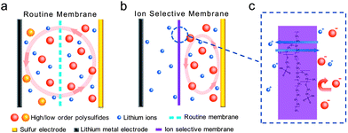
Generally, a battery system consists of a cathode, an anode, a separator, and electrolytes. In most cases, the separator membrane is a porous membrane (e.g. polypropylene (PP), polyethylene (PE), glass fibers), which serves solely as an electronic insulator and does not influence the transportation of ions through the membranes (as shown in Fig. 1a). Polysulfides can diffuse freely through the membranes and react with the anode, which can cause the degradation of the battery. If a cation-selective membrane is introduced in the Li–S cell, the anion of polysulfides will not diffuse through the separator (Fig. 1b), and the shuttle of polysulfides between the cathode and anode can be fully suppressed. Based on this consideration, we explored the idea of ion selective membranes as both an electronic insulator and ionic permselective membrane (cation permselective). To provide the proof-of-the-concept, a multi-functional Nafion-based membrane layer (Fig. 1c) is fabricated for a novel ion selective Li–S configuration. The diffusion of polysulfide is localized on the cathode side and therefore the membrane prevents the shuttle of polysulfides. The cycling stability of the lithium–sulfur battery with this cation permselective membrane can be dramatically improved, with a cycle decay value of 0.08% per cycle for 500 cycles.
Experimental section
Sample preparation and characterization
The Celgard 2400 membrane was employed as received as the cell membrane. Ion selective membranes were prepared by coating Celgard 2400 with Nafion solution and allowing them to dry; the coating amounts were 0.7, 0.15, and 3.5 mg cm−2. The morphology of the separators was characterized using a JEOL JSM 7401F scanning electron microscope (SEM) operated at 1.0 kV.Electrochemical measurements
The cathode electrodes used in the experiments are CNT–S composites (S content 50%). A homogeneous slurry of CNT–S and polyvinylidene fluoride was prepared and coated onto Al foil as the cathode electrode. The sulfur loading amount was 0.53 mg cm−2. Then, 2025 coin-type cells were assembled with Li metal foil as anodes, 1,3-dioxolane (DOL)![[thin space (1/6-em)]](https://www.rsc.org/images/entities/char_2009.gif) :
:![[thin space (1/6-em)]](https://www.rsc.org/images/entities/char_2009.gif) 1,2-dimethoxyethane (DME) (v/v = 1/1) with 1 mol L−1 lithium bis(trifluoromethanesulfonyl)imide (LiTFSI) as the electrolyte, and Celgard 2400 or the ion selective membrane as separators. The electrode preparation and assembling of the coin-type cells was carried out in an Ar-filled glove box (oxygen and water content below 1 ppm). The cyclic voltammogram (scan rate 0.1 mV s−1) and electrochemical impedance spectroscopy measurements were performed on a Solartron 1470E electrochemical workstation. The coin cells were tested in galvanostatic mode at various currents at 25 °C within a voltage range of 1.7–2.8 V using a Neware multi-channel battery cycler.
1,2-dimethoxyethane (DME) (v/v = 1/1) with 1 mol L−1 lithium bis(trifluoromethanesulfonyl)imide (LiTFSI) as the electrolyte, and Celgard 2400 or the ion selective membrane as separators. The electrode preparation and assembling of the coin-type cells was carried out in an Ar-filled glove box (oxygen and water content below 1 ppm). The cyclic voltammogram (scan rate 0.1 mV s−1) and electrochemical impedance spectroscopy measurements were performed on a Solartron 1470E electrochemical workstation. The coin cells were tested in galvanostatic mode at various currents at 25 °C within a voltage range of 1.7–2.8 V using a Neware multi-channel battery cycler.
Visible electrochemical cell test
The visible electrochemical cell test was carried out in an H-type glass cell to examine the properties of the membranes. The whole test was conducted in a glove box to exclude the influence of water and oxygen. Routine Celgard 2400 or ion selective membranes were set in the glass cell. Nickel foams loaded with sulfur and lithium metal foil were set separately in the two cell chambers, with 1.0 M LiTFSI in DOL/DME as the electrolyte. During the test, a potentiostatic method was applied at 2.4 V vs. Li/Li+ to produce lithium polysulfides and the diffusion behavior of polysulfides across the membranes was recorded by an optical camera.Results and discussion
In a routine lithium–sulfur cell, a separator (e.g. Celgard PP/PE/PP membrane) maintains the ionic pathway and blocks the transfer of electrons between the cathode and anode electrodes. The routine membrane shows a flat surface with channels throughout the whole membrane (Fig. 2a). The polymer membrane prevents the direct contact of the anode and cathode electrodes. Besides, the sizes of the channels are around 100 nm, which allow the rapid transportation of ions for electrochemical reactions. By contrast, the novel Nafion–PP/PE/PP composite membrane can prevent the diffusion of polysulfide anions to the anode side. A conformal Nafion layer with a coating amount of 0.7 mg cm−2 was formed on the routine membrane. The channels in the routine membranes were completed covered by the Nafion film (Fig. 2b). The thickness of the Nafion coating film was ca. 1 μm. This compact film structure with cation permselective layers is considered to be efficient to build a complete anion shield between cathode and anode sides.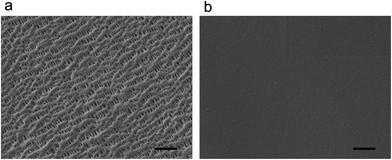 | ||
| Fig. 2 The morphologies of the routine and ion selective membranes. (a) The SEM image of routine PP/PE/PP membrane and (b) ion selective Nafion–PP/PE/PP membrane. Scale bar: 1 μm. | ||
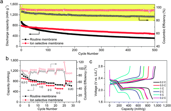
With the introduction of the ion selective membrane, the electrochemical behavior is significantly improved. Coin-type cells were assembled with a CNT–sulfur composite as model cathodes and lithium metal as anodes to evaluate the performance of different membrane systems (Fig. 3a). When the routine membrane was applied, an initial discharge capacity of 906 mA h g−1 was observed at the current density of 1 C (1672 mA g−1 based on the mass of sulfur, corresponding to a current density of 0.89 mA cm−2). A rapid decay in discharge capacity from 906 to 824 mA h g−1 was observed in the first 10 cycles, corresponding to the formation of polysulfides and the loss of sulfur active materials. After the first ten cycles, the decay rate was reduced and decay rate of 0.30% per cycle was observed for the first 100 cycles. After 500 cycles, a discharge capacity of 312 mA h g−1 was obtained, which means 34.4% of the initial capacity was preserved. Meanwhile, the average coulombic efficiency of the cell was 86.6% over the 500 cycles, indicating a severe overcharge during the electrochemical process due to the shuttle of polysulfides.
In contrast, when the ion selective membrane was applied, a much improved cycling stability was achieved. Although the initial discharge capacity declined to 781 mA h g−1, the average cycle decay in the first 100 cycles was reduced to 0.14% per cycle, less than half that of the routine membrane. Even after 500 cycles, over 60% capacity retention was achieved, and a decay rate of 0.08% per cycle was estimated. The average coulombic efficiency in the 500 cycles reached 95.6%, much higher than the cell with routine membrane. The ion selective membrane effectively prevents the diffusion of polysulfide anions through the membrane. Consequently, the reactions between polysulfide and lithium metal were inhibited. Although the shuttle behavior of the polysulfides was blocked by the ion selective membrane, a continuous decay of capacity can still be observed, which may correspond to the combined effect of irreversible deposition of Li2S or Li2S2 and the failure of the conducting network due to the volume change in cycling process.
It also worth mentioning that the loading amount of Nafion plays a critical role in its electrochemical performances. A low amount of Nafion coating (0.15 mg cm−2) cannot lead to the formation of a complete compact film on the polymer backbone and therefore it shows little effect on the electrochemical performance of the lithium–sulfur batteries (Fig. S1a and S2†). One the other hand, a high loading amount of Nafion (3.5 mg cm−2) creates a thick coating layer, which degrades the performance of cell due to severe polarization (Fig. S1b and S2†). The voltage profiles of cells with routine and ion selective membranes are shown in Fig. S3a and b.† Two main discharge plateaus were observed: plateau at around 2.3 V corresponds to the transform from the S8 molecular to a series of soluble polysulfides; the plateau at 2.0 V corresponds to the transform of L2S4 to insoluble Li2S2 and Li2S. No obvious change in the voltage of discharge plateau was shown after the introduction of the ion selective membrane, indicating that the polarization of the cells at this current density is almost negligible if a proper Nafion layer is introduced.
To identify whether the introduction of an ion selective membrane would influence the rate performance of lithium–sulfur cells, the rate performances were also evaluated with different membranes (Fig. 3b). Cells with the ion selective separator presented similar capacity retention until the current density reached 2 C (1.78 mA cm−2), after which the capacity retention is lower than the cell with routine membranes. The voltage profiles for the cell with ion selective membranes offer the two feature plateaus at all the current densities (Fig. 3c). However, the voltage of the two plateaus showed an obvious decrease at 2 and 5 C (1.78 and 4.45 mA cm−2, respectively), which can be attributed to the polarization at high current densities. Although the ion selective membrane shows lower capacities in high-power working conditions, the stability was quite remarkable. When the charge–discharge current was set back to 0.2 C (0.18 mA cm−2) after 25 cycles at different current rates, a capacity retention of 90% can still be achieved for ion selective membrane system, superior to the 73% for the routine membrane system.
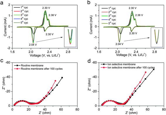
The cyclic voltammogram (CV) profiles were measured to identify the redox reactions for the cells with different membranes (Fig. 4a and b). Two pairs of redox peaks appear in the CV profiles after the first cycle activation. The cathodic peak at 2.30 V and anodic peak at 2.38 V correspond to the transformation between S8 molecular and L2S4, while the cathodic peak at 2.04 V and anodic peak at 2.30 V can be assigned to the transformation between soluble Li2S4 and insoluble Li2S2 or Li2S. The ion selective membrane shows no influence on the electrochemical reactions, and thus shows no effect on the peak positions. Compared with highly-stable lithium–sulfur batteries achieved by adopting covalently-bonded sulfur polymers, which show much lower cathodic potential below 2.0 V,28 the ion selective membrane shows great advantages in maintaining the working voltage of the lithium–sulfur system. As shown in the insert in Fig. 4b, the highly consistent overlap of the cathodic peaks indicates that the electrochemical process is highly stable with the ion selective membrane. As indicated in the electrochemical impedance spectrum (Fig. 4c and d), the coating of the cation permselective layer slightly increases the equivalent series resistance from 2.4 to 3.8 ohm, and no significant influence on the charge transfer resistance is detected, which may be attributed to the ultralow thickness of the ion selective membrane in this case.
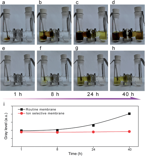
An in situ electrochemical test was also conducted in a glass cell to demonstrate the effect of the ion selective membrane in blocking the shuttle of polysulfides. In the case of cells with the routine membrane (Fig. 5a–d), with the potentiostatic discharge at 2.4 V, the polysulfides continued to be generated on the sulfur cathode (left side, loaded on nickel foam). The polysulfides gradually diffused through the routine membrane and reached the lithium metal side as observed after 24 h (right, loaded on nickel foam). After 40 h, the right chamber contained a high content of polysulfides according to the dark yellow color, in which case the side reaction between polysulfides and lithium metal was inevitable. In contrast, the ion selective Nafion-based membrane is effective to limit polysulfides within the cathode side, and no obvious change of the color in the right chamber can be observed, indicating the membrane played a vital role as a shield for polysulfide anions (Fig. 5e–h). Fig. 5i shows change of the gray level for the anode side chamber with different membranes. The gray level of the chamber with an ion selective membrane stayed at a same level over 40 hours, indicating the great suppression of polysulfide diffusion through the membrane.
The use of an ion selective separator is a general strategy to improve the cycling stability of lithium–sulfur cells. As the shuttle effect originated from the inherent diffusion of polysulfides, the shuttle effect shows a more severe impact at low current working conditions with a prolonged charge–discharge process. The cell performance at low current densities was tested for routine and ion selective membranes. When the current was reduced to 0.1 C, the cell with the routine membrane no longer worked and kept overcharging, which means that the side reaction caused by the shuttle effect exceed the electrochemical reactions. Meanwhile, the cell with the ion selective membrane is still operable with an average decay of 0.38% per cycle and coulombic efficiency of over 90%, indicating a remarkable effect in suppressing the shuttle effect of polysulfides (Fig. S4a†). Similarly, at a charge–discharge current of 0.2 C, the cell equipped with an ion selective separator also offers a much higher cycling stability and higher coulombic efficiency (Fig. S4b†). This type of ion selective membrane is effective for electrodes regardless of their architectures. When applied in a cell with single-walled CNT–sulfur composite electrode, it also showed great advantages in cycling stability and coulombic efficiencies at different working conditions (Fig. S5†).
Meanwhile, the coating of the Nafion layer onto the routine membrane backbone is a simple and facile way to build a complete shield between the cathode and anode electrodes. Other methods, such as direct loading of Nafion onto the cathode electrode, showed worse performance compared with the membrane coating route. As shown in Fig. S6,† when the same amount of Nafion is directly coated onto the cathode electrode, the coulombic efficiency is not obviously improved. This is attributed to the incomplete coating layer on the porous electrode, which cannot fully suppress the diffusion of polysulfides out of the cathode electrode. Moreover, the rate capability test also indicates a poor high power performance at 2 and 5 C, which may be related to the worse electronic conducting network with the incorporation of Nafion as an electronic insulator in the electrode. Therefore, the coating of the membrane backbone to form ion selective membrane is considered more efficient in building highly-stable lithium–sulfur battery systems.
A Nafion film attached on a routine polymer membrane is used as an ion selective membrane system to block the shuttle of polysulfide and therefore improve the cyclic stability of cells. Nafion is one kind of permselective polymer with a tetrafluoroethylene backbone and perfluorovinyl ether groups terminated with sulfonate groups. When serving as a membrane, the sulfonate-ended perfluoroalkyl ether groups are organized as inverted micelles on a lattice. These micelles are connected by pores or channels that are around several nanometers in size. These SO3− groups-coated channels allow for the ion hopping of positively charged species (Li+) but reject negative ions, such as polysulfide anions (Sn2−) in this specific case, due to the coulombic interactions.29 Therefore, with the ion selective membrane, the lithium ions can still transport freely to ensure the working of the battery system and a shield to prevent the transfer of polysulfide anions between cathode and anode sides was built.
The ion selective membranes are highly effective in improving the cycling stability of lithium–sulfur batteries by blocking the diffusion of polysulfide anions. During the electrochemical charge and discharge, polysulfides were generated and diffused into the electrolytes. The ion selective membrane enhanced the performance of the battery through two main routes. On one hand, the diffusion of polysulfide through the membrane was blocked by the ion selective membrane, which prevents the loss of sulfur active materials. On the other hand, the shuttle effect caused by the reaction of polysulfide and lithium metal can be greatly suppressed, which reduced the overcharge and improved the coulombic efficiency of the lithium–sulfur batteries.
Conclusions
In summary, a multi-functional ion selective membrane with permselectivity was fabricated, which allows the free transportation of lithium cations and blocks the shuttle of polysulfides due to the anion naturally by coulombic interactions. The resultant battery cell showed a greatly improved cycling stability with a cyclic decay of 0.08% per cycle within the first 500 cycles, less than half that of the conventional membranes. The use of the ion selective membrane is highly effective in building a complete polysulfide shield, and may be incorporated with a rational cathode structure for further improvements in cycling stability. In addition, this work also offers a general strategy to combine the ion selective membrane with batteries, which is crucial for illustrating the potential of functional membranes for advanced energy storage, probing the role of separator as well as the localized electrochemical environment, and understanding the dynamic changes on the electrode. This approach may also be a novel cell configuration that is applicable to supercapacitors, Li–ion batteries, Li–air batteries, fuel cells, and lab-on-a-chip systems that require good control of the ion in the localized region for high activity and robust cyclability.Acknowledgements
The work was supported by the Foundation for the China National Program (no. 2011CB932602), China Postdoctoral Science Foundation (no. 2012M520293, 2013T60125), and the National Natural Science Foundation of China (21306103). We thank Xiao-Fei Liu and Wancheng Zhu for helpful discussions.References
- C. Liu, F. Li, L. P. Ma and H. M. Cheng, Adv. Mater., 2010, 22, E28 CrossRef CAS PubMed; P. G. Bruce, B. Scrosati and J. M. Tarascon, Angew. Chem., Int. Ed., 2008, 47, 2930 CrossRef PubMed; M. Armand and J. M. Tarascon, Nature, 2008, 451, 652 CrossRef PubMed; J. B. Goodenough and Y. Kim, Chem. Mater., 2010, 22, 587 CrossRef.
- A. Manthiram, Y. Z. Fu and Y. S. Su, Acc. Chem. Res., 2013, 46, 1125 CrossRef CAS PubMed; P. G. Bruce, S. A. Freunberger, L. J. Hardwick and J. M. Tarascon, Nat. Mater., 2012, 11, 19 CrossRef PubMed; S. S. Zhang, J. Power Sources, 2013, 231, 153 CrossRef PubMed.
- X. Ji and L. F. Nazar, J. Mater. Chem., 2010, 20, 9821 RSC.
- R. D. Rauh, K. M. Abraham, G. F. Pearson, J. K. Surprenant and S. B. Brummer, J. Electrochem. Soc., 1979, 126, 523 CrossRef CAS PubMed.
- M. K. Song, E. J. Cairns and Y. Zhang, Nanoscale, 2013, 5, 2186 RSC.
- S. Evers and L. F. Nazar, Acc. Chem. Res., 2013, 46, 1135 CrossRef CAS PubMed; Y. Yang, G. Zheng and Y. Cui, Chem. Soc. Rev., 2013, 42, 3018 RSC; D. W. Wang, Q. C. Zeng, G. M. Zhou, L. C. Yin, F. Li, H. M. Cheng, I. Gentle and G. Q. Lu, J. Mater. Chem. A, 2013, 1, 9382 Search PubMed.
- X. L. Ji, K. T. Lee and L. F. Nazar, Nat. Mater., 2009, 8, 500 CrossRef CAS PubMed.
- R. Elazari, G. Salitra, A. Garsuch, A. Panchenko and D. Aurbach, Adv. Mater., 2011, 23, 5641 CrossRef CAS PubMed.
- S. M. Zhang, Q. Zhang, J. Q. Huang, X. F. Liu, W. C. Zhu, M. Q. Zhao, W. Z. Qian and F. Wei, Part. Part. Syst. Charact., 2013, 30, 158 CrossRef CAS; J. J. Chen, Q. Zhang, Y. N. Shi, L. L. Qin, Y. Cao, M. S. Zheng and Q. F. Dong, Phys. Chem. Chem. Phys., 2012, 14, 5376 RSC; J. Q. Huang, Q. Zhang, S. M. Zhang, X. F. Liu, W. C. Zhu, W. Z. Qian and F. Wei, Carbon, 2013, 58, 99 CrossRef PubMed; S. Dorfler, M. Hagen, H. Althues, J. Tubke, S. Kaskel and M. J. Hoffmann, Chem. Commun., 2012, 48, 4097 RSC; G. M. Zhou, D. W. Wang, F. Li, P. X. Hou, L. C. Yin, C. Liu, G. Q. Lu, I. R. Gentle and H. M. Cheng, Energy Environ. Sci., 2012, 5, 8901 Search PubMed; M. Hagen, S. Dorfler, P. Fanz, T. Berger, R. Speck, J. Tubke, H. Althues, M. J. Hoffmann, C. Scherr and S. Kaskel, J. Power Sources, 2013, 224, 260 CrossRef PubMed.
- N. Jayaprakash, J. Shen, S. S. Moganty, A. Corona and L. A. Archer, Angew. Chem., Int. Ed., 2011, 50, 5904 CrossRef CAS PubMed; C. Zhang, H. B. Wu, C. Yuan, Z. Guo and X. W. Lou, Angew. Chem., Int. Ed., 2012, 51, 9592 CrossRef PubMed; K. Zhang, Q. Zhao, Z. L. Tao and J. Chen, Nano Res., 2013, 6, 38 CrossRef.
- Z. W. Seh, W. Y. Li, J. J. Cha, G. Y. Zheng, Y. Yang, M. T. McDowell, P. C. Hsu and Y. Cui, Nat. Commun., 2013, 4, 1331 CrossRef PubMed.
- J. T. Lee, Y. Zhao, S. Thieme, H. Kim, M. Oschatz, L. Borchardt, A. Magasinski, W. I. Cho, S. Kaskel and G. Yushin, Adv. Mater., 2013, 25, 4573 CrossRef CAS PubMed.
- J. Q. Huang, X. F. Liu, Q. Zhang, C. M. Chen, M. Q. Zhao, S. M. Zhang, W. C. Zhu, W. Z. Qian and F. Wei, Nano Energy, 2013, 2, 314 CrossRef CAS PubMed; Y. L. Cao, X. L. Li, I. A. Aksay, J. Lemmon, Z. M. Nie, Z. G. Yang and J. Liu, Phys. Chem. Chem. Phys., 2011, 13, 7660 RSC; H. Wang, Y. Yang, Y. Liang, J. T. Robinson, Y. Li, A. Jackson, Y. Cui and H. Dai, Nano Lett., 2011, 11, 2644 CrossRef PubMed; G. M. Zhou, L. C. Yin, D. W. Wang, L. Li, S. F. Pei, I. R. Gentle, F. Li and H. M. Cheng, ACS Nano, 2013, 7, 5367 CrossRef PubMed.
- L. W. Ji, M. M. Rao, H. M. Zheng, L. Zhang, Y. C. Li, W. H. Duan, J. H. Guo, E. J. Cairns and Y. G. Zhang, J. Am. Chem. Soc., 2011, 133, 18522 CrossRef CAS PubMed.
- M. Q. Zhao, X. F. Liu, Q. Zhang, G. L. Tian, J. Q. Huang, W. C. Zhu and F. Wei, ACS Nano, 2012, 6, 10759 CAS.
- S. Xin, L. Gu, N. H. Zhao, Y. X. Yin, L. J. Zhou, Y. G. Guo and L. J. Wan, J. Am. Chem. Soc., 2012, 134, 18510 CrossRef CAS PubMed.
- B. Zhang, X. Qin, G. R. Li and X. P. Gao, Energy Environ. Sci., 2010, 3, 1531 CAS.
- Y. Yang, G. H. Yu, J. J. Cha, H. Wu, M. Vosgueritchian, Y. Yao, Z. A. Bao and Y. Cui, ACS Nano, 2011, 5, 9187 CrossRef CAS PubMed.
- J. L. Wang, J. Yang, J. Y. Xie and N. X. Xu, Adv. Mater., 2002, 14, 963 CAS.
- X. Ji, S. Evers, R. Black and L. F. Nazar, Nat. Commun., 2011, 2, 325 CrossRef PubMed.
- Y. S. Su and A. Manthiram, Nat. Commun., 2012, 3, 1166 CrossRef PubMed.
- J. Hassoun and B. Scrosati, Adv. Mater., 2010, 22, 5198 CrossRef CAS PubMed; X. G. Yu, J. Y. Xie, J. Yang and K. Wang, J. Power Sources, 2004, 132, 181 CrossRef PubMed.
- A. Hayashi, T. Ohtomo, F. Mizuno, K. Tadanaga and M. Tatsumisago, Electrochem. Commun., 2003, 5, 701 CrossRef CAS.
- S. S. Zhang, Electrochim. Acta, 2012, 70, 344 CrossRef CAS PubMed.
- L. M. Suo, Y. S. Hu, H. Li, M. Armand and L. Q. Chen, Nat. Commun., 2013, 4, 1481 CrossRef PubMed.
- Z. J. Cai, Y. B. Liu, S. S. Liu, L. Li and Y. M. Zhang, Energy Environ. Sci., 2012, 5, 5690 Search PubMed; Y. B. Liu, Z. J. Cai, L. Tan and L. Li, Energy Environ. Sci., 2012, 5, 9007 Search PubMed; Y. B. Liu, L. Tan and L. Li, Chem. Commun., 2012, 48, 9858 RSC.
- Z. Q. Jin, K. Xie, X. B. Hong, Z. Q. Hu and X. Liu, J. Power Sources, 2012, 218, 163 CrossRef CAS PubMed; Z. Q. Jin, K. Xie and X. B. Hong, RSC Adv., 2013, 3, 8889 RSC.
- L. C. Yin, J. L. Wang, J. Yang and Y. N. Nuli, J. Mater. Chem., 2011, 21, 6807 RSC.
- K. A. Mauritz and R. B. Moore, Chem. Rev., 2004, 104, 4535 CrossRef CAS.
Footnote |
| † Electronic supplementary information (ESI) available. See DOI: 10.1039/c3ee42223b |
| This journal is © The Royal Society of Chemistry 2014 |

