Sb–C nanofibers with long cycle life as an anode material for high-performance sodium-ion batteries†
Lin
Wu
a,
Xiaohong
Hu
*b,
Jiangfeng
Qian
b,
Feng
Pei
c,
Fayuan
Wu
c,
Rongjun
Mao
c,
Xinping
Ai
b,
Hanxi
Yang
b and
Yuliang
Cao
*a
aCollege of Chemistry and Molecular Science, Wuhan University, China. E-mail: ylcao@whu.edu.cn
bHubei Key Lab. of Electrochemical Power Sources, College of Chemistry and Molecular Sciences, Wuhan university, Wuhan 430072, China. E-mail: xhhu88@whu.edu.cn; Tel: +86-027-68754526
cJiangxi Electric Power Research Institute, Nanchang 330096, China
First published on 21st October 2013
Abstract
Sb–C nanofibers are synthesized successfully through a single-nozzle electrospinning technique and subsequent calcination. The structural and morphological characterizations reveal the uniform nanofiber structure with the Sb nanoparticles embedded homogeneously in the carbon nanofibers. Electrochemical experiments show that the Sb–C nanofiber electrode can deliver large reversible capacity (631 mA h g−1) at C/15, greatly improved rate capability (337 mA h g−1 at 5 C) and excellent cycling stability (90% capacity retention after 400 cycles). The superior electrochemical performances of the Sb–C nanofibers are due to the unique nanofiber structure and uniform distribution of Sb nanoparticles in carbon matrix, which provides a conductive and buffering matrix for effective release of mechanical stress caused by Na ion insertion/extraction and prevent the aggregation of the Sb nanoparticles.
Broader contextLithium-ion batteries have attracted great attention for the application of electric vehicles and large-scale energy storage due to their high energy density and long cycle life. However, the cost and resource reserves of lithium will make it hard to meet the requirement of the large-scale applications. Sodium-ion batteries are now actively revisited as one of the most promising alternatives to lithium-ion batteries, because of the low cost and wide availability of sodium resources. Developing advanced Na-storage anode materials with substantially enhanced capacity and cycling capability is a great challenge for energy and materials chemists in the pursuit of efficient energy storage systems. To search for a high performance Na-storage anode, we have successfully synthesized Sb–C nanofibers with very high reversible capacity and excellent cycling stability by a single-nozzle electrospinning technique. This fiber structure and preparation method may be extended to a wide range of electrode-active materials for creating high capacity and cycle-stable sodium-ion batteries. |
Sodium-ion batteries are now actively revisited as a potential alternative to lithium-ion batteries for large-scale electric storage, because of the natural abundance, low cost and environmental benignity of Na resources.1–6 A major challenge in advancing sodium-ion batteries is to find appropriate Na storage electrode materials that are capable of hosting larger Na+ ions (∼1.09 A) with sufficient capacity and diffusion kinetics.1,7–12 Previous work in Na-ion batteries were mostly focused on cathode materials, some of which demonstrated considerable Na-storage capacity, rate capability and cyclability by tailoring the morphology, size and tunnelling structure.3,13–16 On the anode side, earlier works were devoted to Ti-based materials17,18 and carbonaceous materials such as graphitic carbon,19 hard carbon20,21 and hollow carbon nanowires.22 These materials can deliver a reversible capacity of about 250–300 mA h g−1 with certain cycling stability. However, it is difficult to further enhance their capacity due to the limited sodium host sites in the carbon structure. In addition, the sodium inserting potential in carbonaceous materials is very close to the deposition potential of sodium, which easily leads to a safety issue when a slight polarization occurs. Recently, Na alloy electrodes have attracted considerable interest due to their appropriate sodium inserting potential and high theoretical specific capacities, such as Sn (Na15Sn4, 847 mA h g−1) and Sb (Na3Sb, 660 mA h g−1).1,23,24 However, the large volume changes of these materials severely hinder their applications for Na-ion batteries. To solve this problem, a great deal of endeavours have been attempted to develop nanocomposite alloys.25–27 For example, Xiao et al. reported a SbSn–C nanocomposite with a capacity of ∼500 mA h g−1 and good cycling stability, based on the electrochemical Na-alloying–dealloying reactions.24 Some Sb-based nanocomposites were also revealed to have a reversible capacity of ∼600 mA h g−1 with good cycling performance.26–28 These results show that the alloy material is a promising anode material for high-capacity Na-ion batteries. However, the cycling stability of these alloy electrodes still does not meet the requirements of energy storage batteries.
One dimension nanoarchitectures such as nanotubes, nanowires, nanorodes and nanofibers,29–32 are generally considered to be high-capacity and stable electrode materials, due to their uniform structure, orientated electronic and ionic transport, and strong tolerance to stress change. In this work, we report the fabrication of Sb–C nanofibers and describe its superior Na-storage properties as an anodic material for Na-ion batteries.
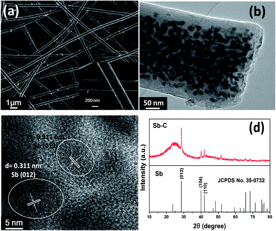
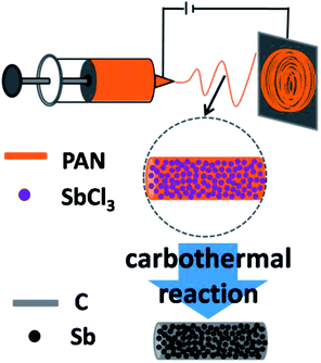
Sb–C nanofibers were synthesized by a single-nozzle electrospinning technique and subsequent calcination (Fig. 1). Fig. 2 shows the morphology and structural features of the Sb–C nanofibers as revealed by SEM, TEM and XRD. The SEM image in Fig. 2a reveals the morphology of the as-electrospun fibers after the carbothermal treatments, which displays individual and uniform nanofibers with a diameter of ∼200 nm. The TEM image reveals that Sb nanoparticles with 15–20 nm diameters are uniformly embedded in the carbon nanofibers (Fig. 2b), appearing as a number of “Sb islands” surrounded by a carbon “ocean”. The high-resolution TEM image in Fig. 2c clearly shows some nanocrystals with ∼20 nm size. The lattice fringes with distances of ∼0.311 nm in the TEM image correspond to the (012) plane of hexagonal Sb (JCPDS no. 35-0732), indicating that Sb particles existed in elemental form in the carbon nanofibers. The crystalline structure of the Sb was also examined by the XRD pattern. As shown in Fig. 2d, all of the XRD peaks can be indexed to the hexagonal Sb (JCPDS no. 35-0732), while no impurities can be detected, implying that Sb3+ was reduced completely to form metallic Sb by a carbothermal reduction reaction. Using the Scherrer equation (D = Kλ/B![[thin space (1/6-em)]](https://www.rsc.org/images/entities/char_2009.gif) cos
cos![[thin space (1/6-em)]](https://www.rsc.org/images/entities/char_2009.gif) θ) to the (012) peaks of Sb, the mean size of the Sb crystallites in the nanofibers was calculated to be about 20 nm, which is in good agreement with the TEM observations in Fig. 2b. The surrounding carbon matrix appears in amorphous structure, acting as a strong buffer to accommodate the mechanical stress during Na insertion and extraction. The metallic Sb content in the Sb–C nanofibers was measured by TGA (ESI, Fig. S1†),33 based on the weight loss of carbon combustion and the weight gain of Sb2O4 formation (ESI, Fig. S2†). The total Sb content in the composite was calculated to be 38% based on the following equation:
θ) to the (012) peaks of Sb, the mean size of the Sb crystallites in the nanofibers was calculated to be about 20 nm, which is in good agreement with the TEM observations in Fig. 2b. The surrounding carbon matrix appears in amorphous structure, acting as a strong buffer to accommodate the mechanical stress during Na insertion and extraction. The metallic Sb content in the Sb–C nanofibers was measured by TGA (ESI, Fig. S1†),33 based on the weight loss of carbon combustion and the weight gain of Sb2O4 formation (ESI, Fig. S2†). The total Sb content in the composite was calculated to be 38% based on the following equation:
 | ||
| Fig. 2 (a) SEM images; (b) TEM image; (c) high resolution TEM image; (d) XRD patterns of the Sb–C nanofibers. | ||
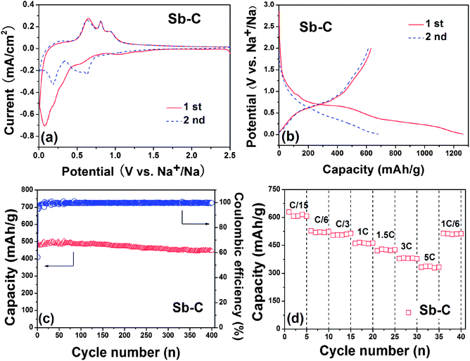
Fig. 3a shows the cyclic voltammograms (CVs) of the Sb–C nanofibers in Na+ electrolyte. During the first negative scan, a weak reduction peak occurs at ∼1.1 V and disappears at the subsequent scans, denoting an irreversible decomposition of the electrolyte for the formation of solid–electrolyte interface (SEI) films. Two reduction peaks at 0.6 V and 0.1 V can be assigned to the alloying reaction of Sb with Na and the insertion reaction of Na in carbon, respectively.22 During the reversed positive scan, three oxidation peaks emerge at 0.65, 0.81 and 0.92 V, corresponding to the extraction reaction of Na in carbon and dealloying reaction of Na–Sb, respectively. At the subsequent scans, the CV curves show three apparent reduction peaks at 0.22, 0.49 and 0.63 V, all of which shift to positive potential and keep stable in their shapes and intensities, suggesting an activation process occurring during first discharge. Obviously, the three oxidation peaks observed at 0.63, 0.81 and 0.91 V in anodic scans correspond to the three step reduction reactions. The pair of redox peaks at 0.22/0.63 V is attributed to the Na-intercalation–deintercalation reaction in carbon.22 The other two pairs of the reversible peaks at 0.63/0.91 V and 0.49/0.81 V suggest two-stepped alloying reactions of Sb with Na to form NaxSb and Na3Sb, which are in accord with a previous report.28 According to previous assignments, the two pairs of CV peaks correspond to the following reactions:
| Sb + xNa+ + xe− ↔ NaxSb | (1) |
| NaxSb + (3 − x)Na+ + (3 − x)e− ↔ Na3Sb | (2) |
Fig. 3b depicts two initial discharge–charge profiles of the Sb–C nanofiber electrode, cycled between 0.01 V and 2.0 V at a current rate of C/15 (40 mA g−1). In accord with the CV evidence, the curve became slightly flat between 0.75 and 0.6 V only for the first discharge, representing the SEI film formation on the Sb–C surface. Another pair of charge and discharge plateaus at ∼0.5 V is related to the reversible Na–Sb alloying–dealloying reactions. The Na storage capability of the Sb particles in the composite was calculated by deducting the capacity contributions from the carbon from pyrolyzed PAN (120 mA h g−1, see ESI, Fig. S3a†) and Super P (90 mA h g−1, see ESI, Fig. S3b†). The Sb–C electrode was found to realize a reversible capacity of 631 mA h g−1, about 95.6% of the theoretical capacity of Na ↔ Na3Sb (660 mA h g−1), suggesting a complete utilization of Sb.
Fig. 3c shows the cycling performance of the Sb–C nanofiber electrode at a C/3 rate (200 mA g−1). The reversible capacity of the Sb–C electrode keeps very stable from 495 mA h g−1 at the first cycle to 446 mA h g−1 after 400 cycles, showing a high capacity retention of 90%. It should be mentioned that the carbon from pyrolyzed PAN can also retain a stable capacity during cycling (ESI, Fig. S4†). For comparison, we prepared a Sb–C composite through conventional methods without the use of the electrospinning process. The Sb content in the composite was measured by TG and calculated to be 35% (ESI, Fig. S5b†). The cycling curve of such a Sb–C composite without electrospinning showed a poor cycling performance with reversible capacity from 503 mA h g−1 at the first cycle to only 45 mA h g−1 after 40 cycles (ESI, Fig. S5a†). The SEM images show the inhomogeneous distribution of Sb in the carbon (ESI, Fig. S5c and d†), possibly due to the segregation of Sb during the dying process. This may be the main cause for the poor electrochemical performance. Additionally, some other Sb–C composites in the literature were also revealed to have a reversible capacity of ∼600 mA h g−1, but only give a cycling performance for 160 cycles.26,27 This phenomenon indicates that the superior cycling stability for the Sb–C nanofibres can be well accounted for by the structural stability of these Sb–C nanofibers. Since the carbon nanofibers provide an effective buffer for the volumetric changes during the alloying–dealloying reaction and a good electrical contact between the Sb particles, the alloying–dealloying reactions of sodium with Sb could proceed repeatedly in a stable electrochemical environment. Though the coulombic efficiency of the Sb–C electrode was 56% for the first cycle (Fig. 3c), it increased rapidly to a very high value of 95% at the 3rd cycle and then remained steady at 99% for subsequent cycles, demonstrating an excellent reversibility for Na-storage reaction. The large initial irreversible capacity is mainly due to the formation of a SEI film and electrochemical decomposition of the solvent on the electrode, which should be alleviated by the use of a film-forming additive to decrease irreversible decomposition of the electrolyte.34 Actually, the contribution of the pyrolyzed carbon from the PAN nanofiber in the irreversible capacity is a main factor, because the pyrolyzed carbon from the PAN nanofiber has a very low initial coulombic efficiency of 35% (ESI, Fig. S3a†). It is noteworthy that a number of the pyrolyzed carbon (62%) is present in the nanofibers, which would put down the initial coulombic efficiency and capacity of the Sb–C electrode. Additionally, the loading of Sb in the electrode is about 0.7 mg cm−2 (2.5 × 0.7 × 0.38), which is low for the practical conditions. However, this study on the Sb–C nanofiber anode for Na ion batteries is only preliminary and provides an approach for a highly-stable Na-storage anode material. For practical applications, a lot of problems still need to be solved in future works, for example, the low content of Sb in the composites and low initial coulombic efficiency. Therefore, to increase the content of Sb in the composites is an important feature for future research to improve the initial coulombic efficiency and meet the requirements of applications.
Fig. 3d shows the rate cycling behaviour of the Sb–C electrode. The Sb–C electrode displays a reversible capacity of 631, 528, 504, 465, 429 and 382 mA h g−1 at C/15, C/6, C/3, 1 C, 1.5 C and 3 C rates (1 C = 600 mA g−1), respectively. Even at 5 C (3000 mA g−1), the electrode can also deliver a good reversible capacity of 337 mA h g−1, which is much higher than that of hard carbon,15 exhibiting excellent rate capability. Particularly, when the current decreased to C/6 after rate cycles, the capacity of the Sb–C electrode recovered completely to 514 mA h g−1, showing a strong tolerance for the rapid Na ion insertion and extraction.
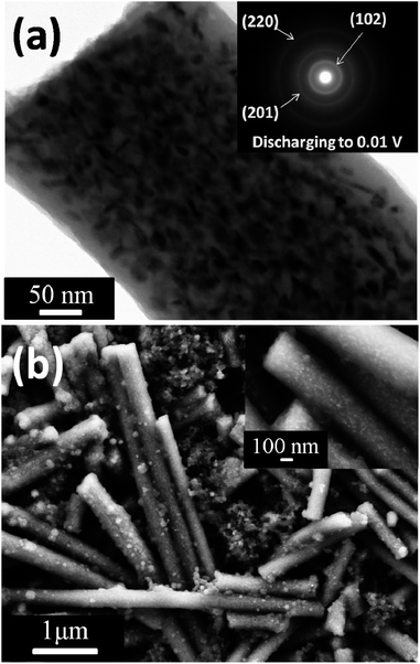
Fig. 4a shows the TEM image and selected area electron diffraction (SAED) pattern of the Sb–C nanofibers after the first discharge. It is clearly observed that the morphology of the carbon nanofibers did not change considerably, only the edge of the nanofiber became fuzzier compared to the Sb–C nanofiber before cycling (Fig. 2b). The alloyed Sb nanoparticles embedded in the carbon fiber still maintain homogenous distribution in the carbon matrix after the first discharge, indicating that the agglomeration of Sb does not occur after the alloying reaction. The d-spacings of the rings in the SAED pattern of the discharged sample (inset in Fig. 4a) can be well indexed to a hexagonal Na3Sb (JCPDS no. 04-0724), which provides strong evidence for the formation of Na3Sb. Additionally, the XRD pattern of the Sb–C nanofiber electrode after the first discharge to 0.01 V (ESI, Fig. S6†) shows four peaks appear at 18.8°, 21.3°, 33.5° and 34.3°, respectively. These peaks can be attributed to the hexagonal Na3Sb (JCPDS no. 04-0724), indicating Na3Sb formation. This result is also in good agreement with the SAED result (inset in Fig. 4a). To provide further evidence for the structural stability of the Sb–C nanofibers, SEM images of the Sb–C nanofibers presented in Fig. 4b were taken from the electrode after 20 cycles to visualize the morphological change of the composites. Compared to the SEM image of uncycled Sb–C nanofibers (Fig. 2a), the cycled nanofibers retained their original size distribution and integrated fiber structure. The magnified SEM image (inset in Fig. 4b) shows that the Sb nanoparticles still keep their original distribution and no cracks were observed on the surface of the nanofibers, indicating the superior structural stability of the Sb–C nanofiber electrode during cycling. These results do demonstrate that the nanofiber structure of the Sb–C composites can not only function effectively for buffering the volumetric changes of the active Sb during charge–discharge cycling, but also provide a good conductive pathway, leading to excellent cycling and rate performance.
In summary, we have successfully prepared Sb–C nanofibers by using a single-nozzle electrospinning technique along with subsequent carbothermal reaction. The as prepared Sb–C materials display a uniform nanofiber structure with the Sb nanoparticles embedded homogenously in the carbon matrix, which provides a structurally stable host for Na-ion intercalation and deintercalation. The Sb–C nanofiber electrode exhibits a high reversible capacity of 631 mA h g−1 at the rate of C/15 (1 C = 600 mA g−1), excellent cyclability with 90% capacity retention over 400 cycles at C/3 rate and a good rate capability with 337 mA h g−1 at 5 C rate. To the best of our knowledge, such a highly stable alloy anode is reported for the first time for Na-ion batteries. These excellent electrochemical performances enable the Sb–C nanofibers to be a promising anode candidate to construct a viable and low-cost Na-ion battery for energy storage systems. Furthermore, these type of metal–carbon nanofibers may be used in a wide range for developing high-performance electrode materials.
Acknowledgements
We are thankful for the financial support by the National Science Foundation of China (no. 21373155, 2133307), Program for New Century Excellent Talents in University (NCET-12-0419), the National high technology development program of China (863, no. 2012AA110102) and the independent research project of state grid corporation of China.Notes and references
- M. D. Slater, D. Kim, E. Lee and C. S. Johnson, Adv. Funct. Mater., 2012, 23, 947–958 CrossRef.
- V. Palomares, P. Serras, I. Villaluenga, K. B. Hueso, J. Carretero-Gonzalez and T. Rojo, Energy Environ. Sci., 2012, 5, 5884–5901 CAS.
- S.-W. Kim, D.-H. Seo, X. Ma, G. Ceder and K. Kang, Adv. Energy Mater., 2012, 2, 710–721 CrossRef CAS.
- V. Palomares, P. Serras, I. Villaluenga, K. B. Hueso, J. Carretero-Gonzalez and T. Rojo, Energy Environ. Sci., 2012, 5, 5884–5901 CAS.
- A. Ponrouch, E. Marchante, M. Courty, J.-M. Tarascon and M. R. Palacin, Energy Environ. Sci., 2012, 5, 8572–8583 CAS.
- A. Ponrouch, R. Dedryvere, D. Monti, A. E. Demet, J.-M. Ateba Mba, L. Croguennec, C. Masquelier, P. Johansson and M. R. Palacin, Energy Environ. Sci., 2013, 6, 2361–2369 CAS.
- S. Y. Hong, Y. Kim, Y. Park, A. Choi, N.-S. Choi and K. T. Lee, Energy Environ. Sci., 2013, 6, 2067–2081 CAS.
- S. P. Ong, V. L. Chevrier, G. Hautier, A. Jain, C. Moore, S. Kim, X. Ma and G. Ceder, Energy Environ. Sci., 2011, 4, 3680–3688 CAS.
- X. Lu, B. W. Kirby, W. Xu, G. Li, J. Y. Kim, J. P. Lemmon, V. L. Sprenkle and Z. Yang, Energy Environ. Sci., 2013, 6, 299–306 CAS.
- S. Komaba, T. Ishikawa, N. Yabuuchi, W. Murata, A. Ito and Y. Ohsawa, ACS Appl. Mater. Interfaces, 2011, 3, 4165–4168 CAS.
- L. Zhao, J. Zhao, Y.-S. Hu, H. Li, Z. Zhou, M. Armand and L. Chen, Adv. Energy Mater., 2012, 2, 962–965 CrossRef CAS.
- H. Pan, Y.-S. Hu and L. Chen, Energy Environ. Sci., 2013, 6, 2338–2360 CAS.
- H. Kim, I. Park, D.-H. Seo, S. Lee, S.-W. Kim, W. J. Kwon, Y.-U. Park, C. S. Kim, S. Jeon and K. Kang, J. Am. Chem. Soc., 2012, 134, 10369–10372 CrossRef CAS PubMed.
- J. Qian, M. Zhou, Y. Cao, X. Ai and H. Yang, Adv. Energy Mater., 2012, 2, 410–414 CrossRef CAS.
- D. Kim, S.-H. Kang, M. Slater, S. Rood, J. T. Vaughey, N. Karan, M. Balasubramanian and C. S. Johnson, Adv. Energy Mater., 2011, 1, 333–336 CrossRef CAS.
- Y. Cao, L. Xiao, W. Wang, D. Choi, Z. Nie, J. Yu, L. V. Saraf, Z. Yang and J. Liu, Adv. Mater., 2011, 23, 3155–3160 CrossRef CAS PubMed.
- Y. Wang, X. Yu, S. Xu, J. Bai, R. Xiao, Y.-S. Hu, H. Li, X.-Q. Yang, L. Chen and X. Huang, Nat. Commun., 2013, 4, 2365 Search PubMed.
- Y. Sun, L. Zhao, H. Pan, X. Lu, L. Gu, Y.-S. Hu, H. Li, M. Armand, Y. Ikuhara, L. Chen and X. Huang, Nat. Commun., 2013, 4, 1870 CrossRef PubMed.
- D. A. Stevens and J. R. Dahn, J. Electrochem. Soc., 2000, 147, 1271–1273 CrossRef CAS PubMed.
- S. Komaba, W. Murata, T. Ishikawa, N. Yabuuchi, T. Ozeki, T. Nakayama, A. Ogata, K. Gotoh and K. Fujiwara, Adv. Funct. Mater., 2011, 21, 3859–3867 CrossRef CAS.
- S. Wenzel, T. Hara, J. Janek and P. Adelhelm, Energy Environ. Sci., 2011, 4, 3342–3345 CAS.
- Y. Cao, L. Xiao, M. L. Sushko, W. Wang, B. Schwenzer, J. Xiao, Z. Nie, L. V. Saraf, Z. Yang and J. Liu, Nano Lett., 2012, 12, 3783–3787 CrossRef CAS PubMed.
- V. L. Chevrier and G. Ceder, J. Electrochem. Soc., 2011, 158, A1011 CrossRef CAS PubMed.
- L. Wu, X. Hu, J. Qian, F. Pei, F. Wu, R. Mao, X. Ai, H. Yang and Y. Cao, J. Mater. Chem. A, 2013, 1, 7181–7184 CAS.
- L. Xiao, Y. Cao, J. Xiao, W. Wang, L. Kovarik, Z. Nie and J. Liu, Chem. Commun., 2012, 48, 3321–3323 RSC.
- J. Qian, Y. Chen, L. Wu, Y. Cao, X. Ai and H. Yang, Chem. Commun., 2012, 48, 7070–7072 RSC.
- L. Wu, F. Pei, R. Mao, F. Wu, Y. Wu, J. Qian, Y. Cao, X. Ai and H. Yang, Electrochim. Acta, 2013, 87, 41–45 CrossRef CAS PubMed.
- A. Darwiche, C. Marino, M. T. Sougrati, B. Fraisse, L. Stievano and L. Monconduit, J. Am. Chem. Soc., 2012, 134, 20805–20811 CrossRef CAS PubMed.
- B. J. Landi, M. J. Ganter, C. D. Cress, R. A. DiLeo and R. P. Raffaelle, Energy Environ. Sci., 2009, 2, 638–654 CAS.
- M.-S. Park, G.-X. Wang, Y.-M. Kang, D. Wexler, S.-X. Dou and H.-K. Liu, Angew. Chem., 2007, 119, 764–767 CrossRef.
- J. Liu, Y. Li, X. Huang, R. Ding, Y. Hu, J. Jiang and L. Liao, J. Mater. Chem., 2009, 19, 1859–1864 RSC.
- T. H. Hwang, Y. M. Lee, B.-S. Kong, J.-S. Seo and J. W. Choi, Nano Lett., 2011, 12, 802–807 CrossRef PubMed.
- Y. Xu, Q. Liu, Y. Zhu, Y. Liu, A. Langrock, M. R. Zachariah and C. Wang, Nano Lett., 2013, 13, 470–474 CrossRef CAS PubMed.
- J. Hassoun, K.-S. Lee, Y.-K. Sun and B. Scrosati, J. Am. Chem. Soc., 2011, 133, 3139–3143 CrossRef CAS PubMed.
Footnote |
| † Electronic supplementary information (ESI) available: Experimental details on the synthesis and electrochemical characterization; TG measurement (Fig. S1), XRD of the combustion product (Fig. S2) and electrochemical performance of the carbon from pyrolyzed PAN nanofibers and super P (Fig. S3). See DOI: 10.1039/c3ee42944j |
| This journal is © The Royal Society of Chemistry 2014 |


