Significant variation of surface spin polarization through group IV atom (C, Si, Ge, Sn) adsorption on Fe3O4(100)
X.
Sun
*ab,
S. D.
Li
a,
B.
Wang
a,
M.
Kurahashi
b,
A.
Pratt
bc and
Y.
Yamauchi
b
aHefei National Laboratory for Physical Sciences at the Microscale and Department of Physics, University of Science and Technology of China, Hefei, Anhui 230026, China. E-mail: sunx@ustc.edu.cn
bNational Institute for Materials Science, 1-2-1 Sengen, Tsukuba, Ibaraki 305-0047, Japan
cDepartment of Physics, University of York, Heslington, York YO10 5DD, UK
First published on 28th October 2013
Abstract
The adsorption of group IV atoms (C, Si, Ge, Sn) on the magnetite Fe3O4(100) surface is investigated by density functional theory calculations. All these atoms prefer to bond to the surface oxygen atom which has no tetrahedral Fe(A) neighbor. The spin-up surface states of clean Fe3O4(100) are completely removed and half-metallicity is recovered by C adsorption. The spin-up band gap of the C-adsorbed Fe3O4(100) surface is wider than that of the H-adsorbed one and closer to the value of bulk Fe3O4. For the adsorption of other group IV atoms, the adsorbate–substrate interaction decreases and the adsorbate–adsorbate interaction increases with the increase of atomic number Z. As a consequence, the spin polarization varies from −99.4% (C adsorption) to +44.2% (Sn adsorption) for the electronic states of the adsorbed atom integrated from −0.5 eV to the Fermi level. The ability to tune the surface spin polarization by the choice of adsorbate is of significance for magnetite-based spintronic devices.
I. Introduction
Organic spintronics continues to attract significant attention, in part due to the weak spin–orbit and hyperfine interactions in organic materials and the associated spin relaxation times which are much longer than in conventional metals and semiconductors.1–7 It has been reported that the spin relaxation time can exceed 1 second in an organic nanowire spin valve of Co/Alq3/Ni.1 A spin diffusion length as long as 13.3 nm has also been measured in junctions with amorphous rubrene and is predicted to reach millimeters in single-crystalline rubrene.2 Beside spin transport, spin injection is a crucial premise to organic spintronics. Spin-polarized currents have been successfully injected into organic materials by contact with conventional ferromagnetic metals such as Fe, Co and Ni.1–5 Recently, special interest6–10 has been shown in magnetite Fe3O4, which has the inverse spinel structure, due to predicted half-metallicity in the bulk and a high Curie temperature.11–13 The half-metallicity of Fe3O4 is characterized by a long demagnetization time, which is two orders of magnitude higher than for Ni, through femtosecond spin excitation.14 However, a significant reduction in the spin polarization at around the Fermi level is observed because of the inevitable presence of a surface or interface. Values of −(55 ± 10)% (Fonin et al.15) and −40% (Tobin et al.16) have been observed for the Fe3O4(100) surface at room temperature using spin-resolved photoemission spectroscopy (SPPES). Theoretical calculations with density functional theory (DFT)17,18 suggest that this reduced surface spin polarization is mainly caused by surface electronic states arising due to O and Fe atoms at the topmost surface layer.To improve the efficiency of spin injection from Fe3O4, it is necessary to enhance the spin polarization at the corresponding surface or interface. Some efforts have been made to achieve this through structural and electronic modifications of the surface by adsorption of hydrogen atoms or molecules.17–24 Among these attempts, the adsorption of hydrogen atoms was found to be an effective way to enhance the surface spin polarization using spin-polarized metastable deexcitation spectroscopy (SPMDS) and SPPES.19,20 DFT calculations confirmed that the half-metallicity can be recovered through atomic hydrogen adsorption at the Fe3O4(100) surface.17,20 However, the −100% spin-polarized electronic states are localized to surface Fe atoms and do not extend to surface O atoms or adsorbed H atoms.17 In order to seek a magnetite surface with a high spin polarization at around the Fermi level not only at Fe atoms but also elsewhere on the surface, we have investigated the adsorption of group IV atoms (C, Si, Ge, Sn) on the Fe3O4(100) surface through DFT calculations. Group IV atoms were chosen because they can easily bond with O atoms and may have a significant effect on the spin polarization of the Fe3O4(100) surface, as for H adsorption. Another reason is that C is one of the main components of most organic materials employed in organic spintronics research. The carbonyl group (C![[double bond, length as m-dash]](https://www.rsc.org/images/entities/char_e001.gif) O) is commonly formed as a reactive intermediate and widely exists in many organic compounds such as ketones, esters, carboxylic acids, etc. Understanding of the nature of the interaction between C and the Fe3O4(100) surface will be helpful for a study of more advanced, functional organic materials with the same substrate. As for Si, Ge and Sn, they are widely-used semiconductor materials for integrated circuit fabrication. The study of spin injection to these materials is significant for spintronics based on present electronic devices. Our calculations predict that the C-adsorbed Fe3O4(100) surface not only has a wider spin-up band gap than the H-adsorbed one, but also that it has the ability to provide a −100% spin-polarized current. Calculations for the adsorption of Si, Ge or Sn atoms are also presented revealing quite different results, even though they belong to the same group.
O) is commonly formed as a reactive intermediate and widely exists in many organic compounds such as ketones, esters, carboxylic acids, etc. Understanding of the nature of the interaction between C and the Fe3O4(100) surface will be helpful for a study of more advanced, functional organic materials with the same substrate. As for Si, Ge and Sn, they are widely-used semiconductor materials for integrated circuit fabrication. The study of spin injection to these materials is significant for spintronics based on present electronic devices. Our calculations predict that the C-adsorbed Fe3O4(100) surface not only has a wider spin-up band gap than the H-adsorbed one, but also that it has the ability to provide a −100% spin-polarized current. Calculations for the adsorption of Si, Ge or Sn atoms are also presented revealing quite different results, even though they belong to the same group.
II. Calculation methods
All calculations were performed within the framework of DFT using a plane-wave basis set, as implemented in the Vienna ab initio simulation package (VASP).25,26 The calculation model and parameters are similar to those in our previous study of H adsorption on the Fe3O4(100) surface.17 Exchange–correlation interactions are described by the Perdew–Burke–Ernzerhof-generalized gradient approximation (GGA).27 The projector-augmented wave method is used to represent the electron–ion interaction.28,29 The Brillouin-zone integration is calculated with a 4 × 4 × 1 k-point grid using the Monkhorst–Pack method.30 All calculations are spin-polarized with a 400 eV plane-wave energy cutoff.A reconstructed substrate is used with a  unit cell, which has been observed by low energy electron diffraction (LEED)15,18 as well as scanning tunneling microscopy (STM)31 and reproduced by DFT calculations.15,18,32 The surface is represented by a 13-layer slab with both sides terminated by octahedral Fe(B) atoms, which is energetically more favorable than a surface terminated by tetrahedral Fe(A) atoms.33,34 The vacuum region is as large as 17.5 Å. Group IV atoms are adsorbed on the topmost and bottom-most surfaces. All adsorbed and substrate atoms are relaxed until the force on each atom is less than 0.01 eV Å−1.
III. Results and discussion
A. Adsorption of C
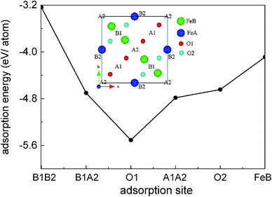
For the Fe(B)-terminated Fe3O4(100) surface, there are two kinds of surface O atom (inset of Fig. 1), denoted as O1 (without an Fe(A) neighbor) and O2 (with an Fe(A) neighbor) in the following text. We investigated the coverage with four adsorbed atoms per unit cell. For C adsorption, the O1 site is the most energetically favorable among the six computed sites shown in Fig. 1. The adsorption energy (5.509 eV) is much larger than for H adsorption (3.096 eV).17 Here, the adsorption energy is defined as Eads = (EFe3O4 + nEC − EC/Fe3O4)/n, where EFe3O4, EC and EC/Fe3O4 are the total energies of the clean Fe3O4(100) surface, a free C atom and the C-adsorbed surface, respectively. The tilting angle of C–O1 bonds from the surface normal (18.1°) is smaller than that of H–O1 bonds (56.3°). The C–O1 bond length (1.21 Å) is very close to that of C
![[double bond, length as m-dash]](https://www.rsc.org/images/entities/char_e001.gif) O bonds (1.23 Å) in carbonyl compounds, indicating strong adsorption of C atoms on the Fe3O4(100) surface.
O bonds (1.23 Å) in carbonyl compounds, indicating strong adsorption of C atoms on the Fe3O4(100) surface.
Fig. 2 shows the band structure and total density of states (DOS) of clean17 and the C-adsorbed Fe3O4(100) surface. An obvious band gap appears in the spin-up electronic band structure (left panel of Fig. 2(b)). Consequently, there are no spin-up electronic states at the Fermi level (right panel of Fig. 2(b)), which means half-metallicity is recovered by C adsorption. The recovery of half-metallicity has been theoretically and experimentally reported for the H-adsorbed Fe3O4(100) surface17,19 and, as discussed in our previous paper,17 the low spin polarization at around the Fermi level on the clean Fe3O4(100) surface is caused by eight spin-up surface state bands (SSB) (Fig. 2(a)). For the H-adsorbed surface, only half of the SSB disappear due to O–H bonding, with the other half remaining but with slightly larger binding energies than those at clean surface. In contrast, no residual SSB are observed in the spin-up band structure in the C-adsorbed surface (Fig. 2(b)). The band gap (Δspin-up) of spin-up electronic states (0.73 eV) is wider than that of the H-adsorbed surface (0.65 eV) and closer to that of the bulk (0.87 eV).17 The energy interval (ΔEF-VBM) from the Fermi level to the valence band maximum (VBM) of C/Fe3O4 is larger than that for H/Fe3O4 by 0.15 eV (Table 1). These larger values for Δspin-up and ΔEF-VBM means they will be more easily resolved in experimental measurements and will be preferable for spintronic device applications. It should be mentioned that the number of adsorbed C atoms is equal to that of available O1 atoms. With a less coverage, the half-metallicity can't be completely recovered since there are still some dangling bonds at the surface. With a more coverage, the adsorbed C atoms assemble with each other, resulting in a stronger adsorbate–adsorbate interaction and a much weaker adsorbate–substrate interaction. The electronic structure of the adsorbed C atom is fairly different from that in Fig. 3.
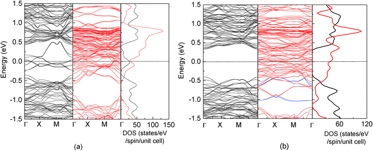 | ||
| Fig. 2 Band structure (left and middle panels) and total density of states (right panel) for a clean17 (a) and C-adsorbed Fe3O4(100) surface (b). Black and red lines represent spin-up and spin-down electronic states, respectively. The spin-down bands which have a strong contribution of C are highlighted with blue lines. | ||
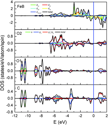 | ||
| Fig. 3 Total and partial DOS of Fe(B), O2, O1 and the adsorbed C atoms. Positive and negative values represent spin-up and spin-down electronic states, respectively. | ||
| H | C | Si | Ge | Sn | Clean surface | |
|---|---|---|---|---|---|---|
| E ads (eV) | 3.096 | 5.509 | 4.575 | 3.629 | 3.144 | |
| E M–M (eV) | 0.293 | 1.081 | 1.676 | 1.621 | 1.786 | — |
| d M–O1 (Å) | 0.970 | 1.210 | 1.648 | 1.851 | 2.078 | — |
| d M–FeB (Å) | 2.762 | 2.479 | 2.729 | 2.823 | 3.047 | — |
| d O1–FeB (Å) | 2.116 | 2.327 | 2.185 | 2.109 | 2.094 | |
| d M–M (Å) | 1.836/4.118 | 2.292/3.661 | 2.693/3.261 | 2.821/3.133 | 2.948/3.006 | — |
| d O1–O1 (Å) | 2.503/3.450 | 2.912/3.042 | 2.770/3.184 | 2.738/3.216 | 2.705/3.249 | 2.457/3.503 |
| d O2–O2 (Å) | 2.861/3.093 | 2.946/3.008 | 2.879/3.075 | 2.761/3.193 | 2.755/3.198 | 2.600/3.354 |
| d FeB–FeB (Å) | 2.560/3.394 | 2.451/3.503 | 2.574/3.380 | 2.745/3.209 | 2.759/3.195 | 2.917/3.037 |
| θ (°) | 56.3 | 18.1 | 1.4 | 1.3 | 3.3 | — |
A magnetite thin film is a potential candidate for the magnetic electrodes of a spintronics device and is expected to inject spin-polarized current into organic materials. At the H/Fe3O4(100) surface, the adsorbed H atoms cannot allow current flow to other molecules at the interface since there are no electronic states around the Fermi level. Conversely, as shown by the local DOS of surface atoms (Fig. 3), significant spin-down peaks at −0.48 eV and −0.96 eV can be observed for C adsorption and an obvious change occurs to the surface O1 and O2 atoms. The corresponding bands which have a strong contribution of the adsorbed C atom are highlighted with blue lines in Fig. 2(b). Additionally, the density of electronic states around the Fermi level becomes considerable (Fig. 3) in contrast to the H/Fe3O4(100) surface where they may be neglected.17 Even the DOS of bare Fe(B) atoms at the C/Fe3O4 surface are much larger than those at the H/Fe3O4 surface. Furthermore, the spin polarization integrated from −0.5 eV to the Fermi level is −97.2%, −86.4%, −97.0% and −99.4%, respectively, for Fe(B), O1, O2 and C atoms at the topmost C/Fe3O4(100) surface. Therefore, in comparison with the H-adsorbed Fe3O4(100) surface, the C-adsorbed Fe3O4(100) surface would be favorable for spintronic devices since it has a much greater ability to create spin-polarized electron densities for organic materials.
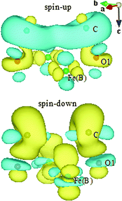
The strong bonding of C–O1 causes significant electron donation and redistribution. To visualize the charge flow, differential charge densities (Fig. 4) are calculated according to the following formula for spin-up and spin-down electronic states, respectively:
| Δρspin-up = ρ(C/Fe3O4)spin-up − ρ(C)spin-up − ρ(Fe3O4)spin-up |
| Δρspin-down = ρ(C/Fe3O4)spin-down − ρ(C)spin-down − ρ(Fe3O4)spin-down |
Now we turn to discuss the differences in the adsorbate–substrate interaction mechanism for H- and C-adsorbed Fe3O4(100) surfaces. It is clear that hybridization mainly occurs through orbitals of H-1s and O1-2p for H/Fe3O4. In contrast, except for s–p hybridization, there is significant p–p hybridization for C/Fe3O4 since the electronic states of C-2p and O1-2p overlap over a wide energy range (two bottom panels of Fig. 3). On the other hand, the interaction between H and Fe(B) is negligible for H/Fe3O4 because the bond length of H–Fe(B) (2.762 Å) is much longer than that of O1–Fe(B) (2.116 Å) and the electronic states of H-1s hardly overlap with those of Fe(B)-3d. In comparison, the bond length of C–Fe(B) (2.479 Å) in C/Fe3O4 is close to that of O1–Fe(B) (2.327 Å) and the overlap between C-2p and Fe(B)-3d is considerable (top and bottom panels of Fig. 3). Therefore, except for the strong interaction with O1 atoms, the adsorbed C atoms also interact with the surface Fe(B) atoms. The direct interaction between C and Fe(B) atoms can be observed in the spin-down differential charge density map (bottom panel of Fig. 4), in which electrons are gained via the dxz(dyz) orbital of Fe(B) atoms, shown in yellow. The s–p and p–p hybridization between C–O1 as well as the p–d hybridization between C–Fe(B) suggest that the interaction of the Fe3O4(100) surface with C atoms is much stronger than that with H atoms. This is consistent with the larger adsorption energy of C atoms (Table 2).
| Bulk Fe3O4 | H/Fe3O4(100) | C/Fe3O4(100) | |
|---|---|---|---|
| Δ spin-up (eV) | 0.87 | 0.65 | 0.73 |
| Δ EF-VBM (eV) | 0.52 | 0.25 | 0.40 |
B. Adsorption of Si, Ge and Sn
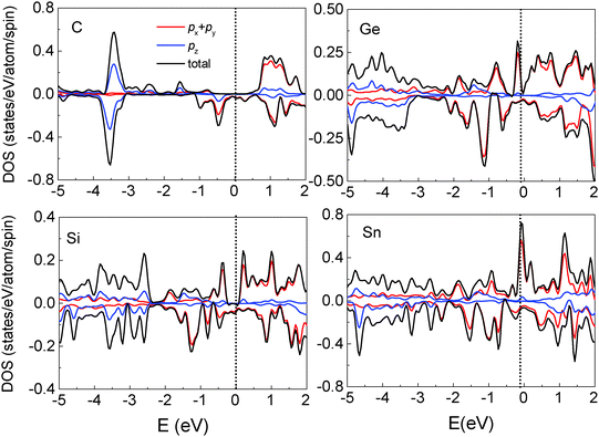
We also investigated the adsorption of other group IV elements such as Si, Ge and Sn on the Fe3O4(100) surface, since they have the same structure of outermost valence electrons and are more easily experimentally realized than C deposition due to lower evaporation temperatures. Si, Ge and Sn atoms adsorb almost vertically on O1 atoms with tilting angles less than 5° (Table 2). The adsorption energy is considerably smaller than that of the C atom and decreases with the increase of the atomic number Z. The bond length of M–O1 (M = Si, Ge and Sn) is longer than that of C–O1 and increases with Z due to the weaker adsorption energy and the larger atomic radius. It is known that the distribution of surface atoms is nonuniform due to surface reconstruction indicated by two values of bond lengths in Table 2. Atomic adsorption can induce variations in the geometric structure of surface atoms. As indicated by the bond lengths of O1–O1, O2–O2 and Fe(B)–Fe(B), the arrangements of the O1 and O2 atoms are more uniform for the adsorption of the low-Z element (C) than for high-Z ones (Si, Ge and Sn). Conversely, the distribution of Fe(B) atoms is more uniform in the adsorption of high Z elements. Thus, compared to the clean substrate, surface modification is largest for C adsorption and smallest for Sn adsorption. Another noticeable feature in the geometric structure is that the bond length of M–Fe(B) is much longer than that of O1–Fe(B) when Si, Ge or Sn atoms are adsorbed, indicating that the interaction between the adsorbate and surface Fe(B) atoms is negligible for high-Z element adsorption.Compared to C adsorption, the Si-, Ge- or Sn-adsorbed Fe3O4(100) surfaces show clear variations in the band structure (Fig. 5). Several spin-up SSB appear with some of them crossing the Fermi level, eliminating half-metallicity. The appearance of spin-up SSB at the clean Fe3O4(100) surface (Fig. 2(a)) can be dominantly attributed to the contributions of surface O1, O2 and Fe(B) atoms.17 For Si-, Ge-, Sn-adsorbed Fe3O4(100) surfaces, the band-decomposed charge density (not shown) indicates that the SSB not only contains contributions from surface O1, O2 and Fe(B) atoms, but also from the adsorbed Si, Ge or Sn atoms. Some bands which have a strong contribution of adsorbate are highlighted with blue lines in Fig. 5. The substantial contribution of the adsorbates can also be observed in the local DOS. There are significant spin-up states around the Fermi level in the adsorbed Si, Ge and Sn atoms (Fig. 6). These states are caused by the adsorbate–adsorbate (M–M) interaction but not the adsorbate–substrate interaction because they mainly consist of px(py) orbitals and not pz orbitals (Fig. 6). We also calculated the adsorbate–adsorbate (M–M) interaction energy (Table 2), which is defined as: EM–M = (nEM − EnM)/n, where EM and EnM are the total energies of a free M (M = Si, Ge, or Sn) atom and a set of n-adsorbed M atoms with the same geometric structure of the adsorption system. The M–M interaction energy of Si, Ge and Sn is larger than that of C by 0.595, 0.540 and 0.705 eV per atom, respectively. Thus, both the weakening of the adsorbate–substrate interaction and the enhancement of the adsorbate–adsorbate interaction are responsible for the appearance of SSB as well as disappearance of the half-metallicity.
The surface electron spin polarization is one of the most important indices in spintronic devices and, since it is located at the surface, the spin polarization of the adsorbate is essential for the operation of a device. Of relevance to the limited energy resolution typical of experiments, the spin polarization integrated from −0.5 eV to the Fermi level is −99.4% for the C adsorption surface and +44.2% for Sn adsorption. This means that the polarity of surface spin polarization may be tuned by the choice of adsorbate, offering an additional advantage in using group IV elements to modify the surface properties of magnetite Fe3O4.
C. Strong electronic correlation effect
Calculations including the on-site Coulomb interaction (U) term for treating the electron-correlation effects have been proved to be successful in giving a reasonably good explanation of experimental optical spectra of Fe3O4.35,36 In this study, we also conducted the calculation with the GGA + U method to investigate the effects of the electron correlation on the surface spin polarization. Coulomb (U) and exchange parameters (J) of 4.5 eV and 0.89 eV were used. The geometric and electronic structures of the clean Fe3O4(100) surface by GGA + U calculation have been discussed in ref. 37–40. For C adsorption, compared with GGA calculation, GGA + U yields a slight decrease of the bond length of C–O1 by 0.007 Å and increases of C–Fe(B) and C–C by 0.067 Å and 0.088 Å, respectively. The tilting angle of C–O1 decreases by 3.1°. The above means that the variation of geometric structure related to the adsorbate is insignificant. Geometric variation also occurs at deep layers. For example, the bond length of O–O changes by about 0.041, 0.031 and 0.012 Å for the first, second and third Fe(B)–O layer, respectively. The adsorption energy of C with GGA + U is 4.956 eV, which still indicates a strong chemical adsorption. The effect on the electronic structure and surface spin polarization by the atomic reconstruction is much less than those by the strong electronic correlation effect and the chemical bonding of C–O1 and not discussed here. Fig. 7(a) shows the total and partial DOS of surface atoms and Fe(B) in the second Fe(B)–O layer calculated with GGA + U. Compared with the local DOS in Fig. 3, the gap of spin-up electronic states is obviously enlarged. Furthermore, a gap is opened for the spin-down electronic states of the surface Fe(B) atom (2nd panel). The corresponding 2p states of C, O1 and O2 atoms, which overlap with Fe(B)-3d states, are shifted toward the deep level (3rd–5th panel). Such a deep level shift results in hardly any electronic states around the Fermi level for the adsorbate and all surface atoms. But there are considerable states located from −1.2 eV to −0.4 eV with −100% spin polarization. It should be mentioned that the gap opening is only for the atoms at the topmost surface. There are significant spin-down electronic states around the Fermi level for Fe(B) atoms at the second Fe(B)–O layer (topmost panel) and deeper layers, which indicates the half metallic behavior of the whole system. A similar gap opening of 0.3 eV due to the strong correlation effect has also been observed for surface atoms of clean Fe3O4(100).37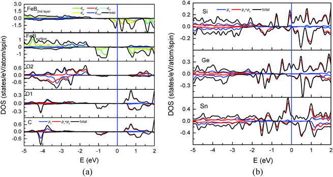 | ||
| Fig. 7 (a) Total and partial DOS of C, O1, O2 atoms and Fe(B) atoms at the topmost and the 2nd layer. (b) Local DOS of the adsorbed Si, Ge and Sn atoms calculated using the GGA + U method. | ||
Similar to C adsorption, the adsorption energy calculated with GGA + U is smaller than that with GGA by 0.353, 0.176 and 0.094 eV, respectively, for Si, Ge and Sn adsorption. The geometric variation related to the adsorbate is minor. Fig. 7(b) shows the total and partial DOS of the adsorbed Si, Ge and Sn atoms with GGA + U calculation. Compared with Fig. 6, both spin-up and spin-down electronic states are shifted to a deep level for all the three adsorbates. Significant spin-up states contributed by px(py) orbitals can be observed around the Fermi level due to the adsorbate–adsorbate interaction. Consequently, the polarity of the spin polarization around the Fermi level remains positive, which is the same as that by GGA calculation.
IV. Conclusion
The electronic and magnetic properties of C-, Si-, Ge- and Sn-adsorbed Fe3O4(100) surfaces were investigated and compared with those of the H-adsorbed Fe3O4(100) surface. The adsorption of C is stronger than that of H atoms and can also restore half-metallicity to the surface. The C-modified Fe3O4(100) surface could also provide better device performance than for H-adsorption both due to the ability to inject spin-polarized electron density to organic materials and due to the width of the spin-up band gap. In comparison, modification by other group IV elements, such as Si, Ge, and Sn, did not restore the half-metallicity of bulk Fe3O4(100). The reason can be attributed to the weakening of the adsorbate–substrate interaction and the strengthening of the adsorbate–adsorbate interaction for the high-Z element adsorption.Acknowledgements
This work was supported by the National Basic Research Program of China (973 Program) under Grant No. 2012CB933702, and the Natural Science Foundation of China under Grant No. 11179008, 90921013, and 11274284.References
- S. Pramanik, C. G. Stefanita, S. Patibandla, S. Bandyopadhyay, K. Garre, N. Harth and M. Cahay, Nat. Nanotechnol., 2007, 2, 216 CrossRef CAS PubMed.
- J. H. Shim, K. V. Raman, Y. J. Park, T. S. Santos, G. X. Miao, B. Satpati and J. S. Moodera, Phys. Rev. Lett., 2008, 100, 226603 CrossRef CAS.
- L. Schulz, L. Nuccio, M. Willis, P. Desai, T. Kreouzis, V. K. Malik, C. Bernhard, F. L. Pratt, N. A. Moriey, A. Suter, G. J. Nieuwenhuys, T. Prokscha, E. Morenzoni, W. P. Gillin and A. J. drew, Nat. Mater., 2011, 10, 39 CrossRef CAS PubMed.
- A. R. Rocha, V. M. García-Suárez, S. W. Bailey, C. J. Lambert, J. Ferrer and S. Sanvito, Nat. Mater., 2005, 4, 335 CrossRef CAS PubMed.
- S. Steil, N. Großmann, M. Laux, A. Ruffing, D. Steil, M. Wiesenmayer, S. Mathias, O. L. A. Monti, M. Cinchetti and M. Aeschlimann, Nat. Phys., 2013, 9, 242 CrossRef CAS.
- E. Arisi, I. Bergenti, M. Cavallini, A. Riminucci, G. Ruani, V. Dediu, M. Ghidini, C. Pernechele and M. Solzi, Appl. Phys. Lett., 2008, 93, 113305 CrossRef.
- S. Berny, L. Tortech, D. Fichou, S. Matzen and J.-B. Moussy, Appl. Phys. Lett., 2010, 97, 253303 CrossRef.
- A. Pratt, L. Dunne, X. Sun, M. Kurahashi and Y. Yamauchi, J. Appl. Phys., 2012, 111, 07C114 CrossRef.
- N. Mulakaluri and R. Pentcheva, J. Phys. Chem. C, 2012, 116, 16447 CAS.
- F. J. Yue, S. Wang and D. Wu, Appl. Phys. A: Mater. Sci. Process., 2013, 111, 347 CrossRef CAS.
- Z. Zhang and S. Satpathy, Phys. Rev. B: Condens. Matter Mater. Phys., 1991, 44, 13319 CrossRef CAS.
- P. A. Dowben and R. Skomski, J. Appl. Phys., 2004, 95, 7453 CrossRef CAS.
- M. Fonin, Y. S. Dedkov, R. Pentcheva, U. Rüdiger and G. Güntherodt, J. Phys.: Condens. Matter, 2007, 19, 315217 CrossRef CAS PubMed.
- G. M. Müller, J. Walowski, M. Djordjevic, G. Miao, A. Gupta, A. V. Ramos, K. Gehrke, V. Moshnyaga, K. Samwer, J. Schmalhorst, A. Thomas, A. Hütten, G. Reiss, J. S. Moodera and M. Münzenberg, Nat. Mater., 2009, 8, 56 CrossRef PubMed.
- M. Fonin, R. Pentcheva, Y. S. Dedkov, M. Sperlich, D. V. Vyalikh, M. Scheffler, U. Rüdiger and G. Güntherodt, Phys. Rev. B: Condens. Matter Mater. Phys., 2005, 72, 104436 CrossRef.
- J. G. Tobin, S. A. Morton, S. W. Yu, G. D. Waddill, I. K. Schuller and S. A. Chambers, J. Phys.: Condens. Matter, 2007, 19, 315218 CrossRef CAS PubMed.
- X. Sun, M. Kurahashi, A. Pratt and Y. Yamauchi, Surf. Sci., 2011, 605, 1067 CrossRef CAS PubMed.
- R. Pentcheva, W. Moritz, J. Rundgren, S. Frank, D. Schrupp and M. Scheffler, Surf. Sci., 2008, 602, 1299 CrossRef CAS PubMed.
- M. Kurahashi, X. Sun and Y. Yamauchi, Phys. Rev. B: Condens. Matter Mater. Phys., 2010, 81, 193402 CrossRef.
- G. S. Parkinson, N. Mulakaluri, Y. Losovyj, P. Jacobson, R. Pentcheva and U. Diebold, Phys. Rev. B: Condens. Matter Mater. Phys., 2010, 82, 125413 CrossRef.
- A. Pratt, M. Kurahashi, X. Sun and Y. Yamauchi, J. Phys. D: Appl. Phys., 2011, 44, 064010 CrossRef.
- N. Mulakaluri, R. Pentcheva and M. Scheffler, J. Phys. Chem. C, 2010, 114, 11148 CAS.
- Y. Joseph, W. Ranke and W. Weiss, J. Phys. Chem. B, 2000, 104, 3224 CrossRef CAS.
- A. Pratt, M. Kurahashi, X. Sun, D. Gilks and Y. Yamauchi, Phys. Rev. B: Condens. Matter Mater. Phys., 2012, 85, 180409 CrossRef (R).
- G. Kresse and J. Furthmüller, Phys. Rev. B: Condens. Matter Mater. Phys., 1996, 54, 11169 CrossRef CAS.
- G. Kresse and J. Furthmüller, Comput. Mater. Sci., 1996, 6, 15 CrossRef CAS.
- J. P. Perdew, K. Burke and M. Ernzerhof, Phys. Rev. Lett., 1996, 77, 3865 CrossRef CAS.
- G. Kresse and D. Joubert, Phys. Rev. B: Condens. Matter Mater. Phys., 1999, 59, 1758 CrossRef CAS.
- P. E. Blöchl, Phys. Rev. B: Condens. Matter Mater. Phys., 1994, 50, 17953 CrossRef.
- H. J. Monkhorst and J. D. Pack, Phys. Rev. B: Solid State, 1976, 13, 5188 CrossRef.
- I. V. Shvets, G. Mariotto, K. Jordan, N. Berdunov, R. Kantor and S. Murphy, Phys. Rev. B: Condens. Matter Mater. Phys., 2004, 70, 155406 CrossRef.
- Z. Lodziana, Phys. Rev. Lett., 2007, 99, 206402 CrossRef.
- R. Pentcheva, F. Wendler, H. L. Meyerheim, W. Moritz, N. Jedrecy and M. Scheffler, Phys. Rev. Lett., 2005, 94, 126101 CrossRef CAS.
- C. Cheng, Phys. Rev. B: Condens. Matter Mater. Phys., 2005, 71, 052401 CrossRef.
- I. Leonov, A. N. Yaresko, V. N. Antonov and V. I. Anisimov, Phys. Rev. B: Condens. Matter Mater. Phys., 2006, 74, 165117 CrossRef.
- V. N. Antonov, B. N. Harmon, V. P. Antropov, A. Y. Perlov and A. N. Yaresko, Phys. Rev. B: Condens. Matter Mater. Phys., 2001, 64, 134410 CrossRef.
- Z. Łodziana, Phys. Rev. Lett., 2007, 99, 206402 CrossRef.
- H. C. Wu, O. N. Mryasov, M. Abid, K. Radican and I. V. Shvet, Sci. Rep., 2013, 3, 1830 CAS.
- Z. Novotny, N. Mulakaluri, Z. Edes, M. Schmid, R. Pentcheva, U. Diebold and G. S. Parkinson, Phys. Rev. B: Condens. Matter Mater. Phys., 2013, 87, 195410 CrossRef.
- I. Leonov, A. N. Yaresko, V. N. Antonov, M. A. Korotin and V. I. Anisimov, Phys. Rev. Lett., 2004, 93, 146404 CrossRef CAS.
| This journal is © the Owner Societies 2014 |

