A hierarchically structured composite of Mn3O4/3D graphene foam for flexible nonenzymatic biosensors†
Received 4th September 2012, Accepted 24th September 2012
First published on 25th September 2012
Abstract
We report a novel composite material of hierarchically structured Mn3O4 grown on three-dimensional graphene foam (3DGF). This hierarchical Mn3O4/3DGF composite was fabricated as a flexible and freestanding biosensor for nonenzymatic determination of glucose and H2O2, significant analytes in health care and food industry. The Mn3O4/3DGF-based biosensor achieved high sensitivity, large linear range and low detection limit for the detection of both analytes, due to the synergistic effects of the two materials, which combines the high electrocatalytic activity of the nanostructured Mn3O4 network, and high conductivity and large surface area of 3DGF. This enzymeless biosensor also exhibited excellent performance for real-time detection of glucose and H2O2 in serum and food samples.
Introduction
The determination of glucose level in blood is commonly used for medical diagnosis of diabetes mellitus, which is a worldwide health problem resulting from insulin dependency and hyperglycemia.1 Hydrogen peroxide (H2O2) has been widely used as an oxidant in industrial processes, antibacterial reagent in food industry and cleaning agent in environmental protection.2 Consequently, sensitive and reliable monitoring of these two analytes is of paramount importance in clinical, food and environmental analysis. Currently, most glucose and H2O2 sensors rely on enzyme-based electrodes which employ glucose oxidase, horseradish peroxidase or hemoglobin as a catalyst.3–6 Although the enzyme-based approaches provide an additional capability of selective measurement to the sensors, several drawbacks have hindered their widespread use. Due to the intrinsic nature of proteins, the enzymatic sensors have poor stability which prevents them from long-term and reproducible usage. In addition, the enzyme-based detection is susceptible to the environmental factors, such as pH, temperature, and humidity. Furthermore, the incorporation of enzymes also increases the manufacturing cost and complexity, and the insulating property of enzymes greatly compromises the sensitivity of biosensors. To address these issues, great effort has been dedicated in recent years to the development of enzymeless electrodes using metals,7 metallic nanoparticles,8,9 alloys10,11 and oxides12,13 as an electrocatalyst. However, many nonenzymatic electrodes display low sensitivity, poor selectivity and severe surface fouling due to the adsorption of intermediates and chlorides.11,14 Hence, there is a great demand for the development of nonenzymatic biosensors with high sensitivity, good selectivity, and poison resistance at low cost for the efficient determination of both glucose and H2O2.Graphene has been integrated with other functional nanomaterials to fabricate composite materials. The attained synergistic effects of the graphene composite provide vast opportunities that lead to advances in energy harvesting/storage devices,15–19 transparent conductors20–22 and chemical/bio-sensors.23–25 Recently, highly conductive and seamless three-dimensional graphene foam (3DGF) with a microscopic network structure has been synthesized by template-directed chemical vapor deposition (CVD),26 enabling the production of graphene with both high quality and relatively large quantity. The mechanical strength and flexibility of 3DGF allow it to be used as a freestanding electrode, where charge carriers could move along the continuous graphene skeleton with a small resistance. In addition, the three dimensional architecture of 3DGF provides a large surface area which allows for the construction of graphene-based nanocomposites without agglomeration. Recently, we reported a composite material of Co3O4/3DGF for the nonenzymatic biosensing of glucose.27 Despite extraordinarily high sensitivity it achieved, the Co3O4/3DGF biosensor offers a relatively small linear response range (up to 80 μM) due to the thick coating layer of Co3O4. Moreover, Co3O4/3DGF could not be used for the detection of H2O2. In the present work, we synthesized a novel composite material of hierarchically structured Mn3O4/3DGF for the development of a highly sensitive and enzymeless sensor for detection of both glucose and H2O2. Due to the excellent electrocatalytic activity of nanostructured Mn3O4, good conductivity of graphene, great abundance of catalytic sites and high specific surface area of the composite material, the Mn3O4/3DGF-based glucose sensor achieved a large linear detection range of 0.1–8 mM, which is 2 orders of magnitude larger than that of 3DGF/Co3O4. In addition, the material also showed the capability of highly sensitive and selective detection of H2O2. Moreover, thanks to the good stiffness of 3DGF, the composite material can be fabricated as a flexible and freestanding biosensor.
Results and discussion
Fig. 1a shows the SEM image of 3DGF grown by the ethanol-CVD method using nickel foam as a sacrificial template. The 3DGF reveals the macroporous network structure that replicates the nickel foam, hence exhibiting a continuous and smooth graphene skeleton without observable cracks or breaks, indicating that graphene sheets well maintain their original structure after removal of the Ni template without collapse. The width of the graphene skeleton is around 100 μm. In Fig. 1b, the observed wrinkles and ripples on the surface of the 3DGF skeleton result from difference in the thermal expansion coefficients of nickel and graphene.28 Similar to the effect of wrinkles of chemically derived graphene,29 these ripples on the 3DGF skeleton could contribute to the large surface area and the good mechanical strength of 3DGF. The surface morphology of Mn3O4/3DGF is shown in Fig. 1c and d, displaying good uniformity of Mn3O4 nanostructures on the graphene surface. The magnified SEM image (Fig. 1e) shows the highly porous and nanomesh-like structure of the Mn3O4, which is uniformly covered on the entire surface of 3DGF. The TEM image (Fig. 1f) shows that the microstructure of Mn3O4 grown on graphene is composed of ultrathin nanoflaklets with the dimension of 100–200 nm. With uniform distribution of the hierarchical structure at the nanometer scale, the Mn3O4 nanomesh offers abundant catalytic sites, which contributes to the high electrocatalytic activity of the composite material. The nanoporous Mn3O4 network together with the macroporous structure of 3DGF provides a high specific surface area, which was estimated by the Brunauer–Emmett–Teller (BET) method to be 1157.9 m2 g−1, much larger than that of ∼850 m2 g−1 of bare 3DGF.26 The improved surface area allows for the rapid access of electrolyte ions, provides abundant active sites for the electrocatalytic reactions, and facilitates fast electron transport between the electrode materials and the analytes. Taking advantage of the flexibility and robustness of 3DGF, the composite material was fabricated as a flexible biosensor and used as a monolithic electrode for the measurement of analytes of interest (Fig. S1†).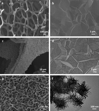 |
| | Fig. 1 (a and b) Low- and high-magnification SEM images of the CVD-grown 3DGF. (c and d) Low- and high-magnification SEM images of the Mn3O4/3DGF composite. (e and f) SEM and TEM images of the hierarchically structured Mn3O4 nanomesh grown on the surface of the 3DGF skeleton. | |
The phase purity of the Mn3O4/3DGF composite was analyzed by XRD. As shown in Fig. 2a, the XRD spectrum of 3DGF shows two notable diffraction peaks at 2θ = 26.5° and 54.6° corresponding to the (002) and (004) reflections of graphitic carbon, respectively (JCPDS 75-1621). On the XRD spectrum of the Mn3O4/3DGF composite, besides the characteristic peaks of graphene, strong diffraction peaks are well indexed to the (101), (112), (103), (211), (224), and (004) phases of the tetragonal hausmannite Mn3O4 structure (a = 5.762 Å, c = 9.469 Å, JCPDS card no. 24-0734). The result shows that no impurity phase exists in the Mn3O4/3DGF composite. As a control experiment, we also investigated the XRD pattern of as-synthesized MnOx/3DGF before calcination. The as-formed MnOx on 3DGF did not show any diffraction peaks, possibly due to the poor crystallinity of MnOx. The difference in the XRD patterns between the as-synthesized MnOx/3DGF and the calcinated Mn3O4/3DGF suggests that significant change of the MnOx crystal structure occurs during the calcination process. The phase purity of the Mn3O4/3DGF composite was also confirmed by energy-dispersive X-ray spectroscopy (EDX) (Fig. 3), showing strong peak signals of only C, Mn, and O, components of the Mn3O4/3DGF composite. In further analysis by Raman spectroscopy (Fig. 2b), 3DGF shows distinct peaks at 1581 cm−1 and 2725 cm−1, which are attributed to the G and 2D bands of single- to a few layers of graphene.30,31 It is worth mentioning that the D band (∼1350 cm−1) cannot be discerned on the 3DGF spectrum, suggesting that the CVD-grown graphene foam possesses high quality since the D band is an indication of defects and distorted carbon.32,33 On the Raman spectrum of Mn3O4/3DGF, the peaks observed at 314, 360, 480 and 650 cm−1 are ascribed to the characteristic A1g, F2g(1), F2g(2) and Eg modes of crystalline Mn3O4, respectively.34,35 Both XRD and Raman spectroscopy results corroborate successful integration of the Mn3O4 with the 3DGF. The content of Mn3O4 in the composite was measured by thermogravimetric analysis (TGA) (Fig. 4). The large weight loss appeared at ∼600 °C for both 3DGF and Mn3O4/3DGF results from the decomposition of 3DGF carbon, which combust completely at 800 °C. The total weight loss of Mn3O4/3DGF is 55.84 wt%, we can thus estimate the amount of Mn3O4 present in the composite to be 44.16 wt%.
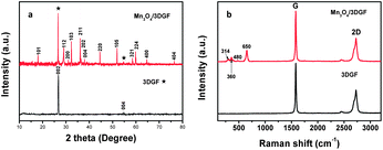 |
| | Fig. 2 XRD (a) and Raman (b) spectra of 3DGF (black) and the Mn3O4/3DGF composite (red). | |
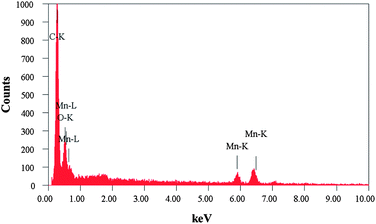 |
| | Fig. 3 Energy-dispersive X-ray (EDX) spectrum of the Mn3O4/3DGF composite material. | |
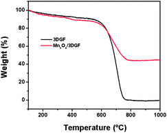 |
| | Fig. 4 TGA curves of 3DGF and the Mn3O4/3DGF composite. | |
The electrocatalytic behavior of Mn3O4 toward the oxidation of glucose was studied by cyclic voltammetry (CV) in 0.1 M NaOH solution. Fig. 5a shows the CVs of Mn3O4/3DGF measured at different scan rates. At the scan rate of 5 mV s−1, two pairs of redox peaks are observed at the potentials of 0.16 V/0.03 V (I/II) and 0.26 V/0.18 V (III/IV), which may attribute to the reversible transition between Mn3O4/MnOOH and MnOOH/MnO2, respectively. With an increase of the scan rate, both the anodic- and cathodic peak currents increase. The intensities of redox currents exhibit good linearity against the scan rate (Fig. 5b), indicating a surface-confined electrochemical process. Upon the introduction of glucose, notable current increase at the anodic peak (III) is observed on the CV curve at a scan rate of 20 mV s−1, while the cathodic peak currents remain constant (Fig. 5c). The result suggests that the electrooxidation of glucose could be catalyzed by MnO2 presumably due to the following reaction:
| | | 2MnO2 + C6H12O6 (glucose) → 2MnOOH + C6H10O6 | (1) |
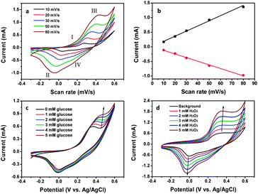 |
| | Fig. 5 (a) CV curves of the Mn3O4/3DGF composite electrode recorded at different scan rates (from inside to outside: 10, 20, 30, 50 and 80 mV s−1) in 0.1 M NaOH solution. (b) Plots of the scan rate versus peak currents at (II) and (III). (c) CVs of the composite electrode recorded at 20 mV s−1 in the presence of different concentrations of glucose (from inside to outside: 0, 1, 2, 3, 4, and 5 mM). (d) CVs of the composite electrode recorded at 20 mV s−1 in the presence of different concentrations of H2O2 (from inside to outside: 0, 1, 2, 3, 4, and 5 mM). | |
In contrast, when H2O2 was added, increase of both anodic and cathodic peak currents was observed with the increase of H2O2 concentration (Fig. 5d). This could contribute to the bi-electrocatalytic property of nanostructured Mn3O4 toward H2O2. We propose the possible mechanism as follows. On one hand, upon the addition of H2O2, MnO2 is reduced to MnOOH, which is then electro-oxidized back to MnO2 (eqn (2) and (3)). This reaction results in the increase of anodic current at peak (III). On the other hand, Mn3O4 could be oxidized by H2O2 to MnOOH, which is further electrochemically reduced back to Mn3O4 (eqn (4) and (5)), resulting in the increment of cathodic current at peak (II).
| | | 2MnO2 + H2O2 → 2MnOOH + O2 | (2) |
| | | MnOOH + OH− → MnO2 + H2O + e− | (3) |
| | | 2Mn3O4 + H2O2 + 2H2O → 6MnOOH | (4) |
| | | 3MnOOH + e− → Mn3O4 + OH− + H2O | (5) |
Next, real-time and enzymeless detection of glucose was studied by addition of various concentrations of glucose to a homogeneously stirred 0.1 M NaOH solution at a fixed potential of 0.4 V, where the most significant increase of voltammetric current was observed. Fig. 6a shows the amperometric responses of the Mn3O4/3DGF monolithic electrode to successive addition of 1 mM and 100 μM glucose. A remarkable increase and fast response of amperometric current is observed by the Mn3O4/3DGF, which reaches 95% of the steady state current within 5 s upon the addition of glucose. The calibration curve of the Mn3O4/3DGF is plotted in Fig. 6b, showing a high sensitivity of 360 μA mM cm−2 and a large linear range of 0.1–8 mM. The sensitivity of Mn3O4/3DGF is much superior to those enzymatic or enzymeless glucose sensors based on chemically derived graphene,10,36–44 most of which are in the range of 1–50 μA mM cm−2. Furthermore, in contrast to the small linear range of Co3O4-based enzymeless glucose sensors,12,27 the Mn3O4/3DGF could be used to study the sugar level in human blood, which is usually in the range of 4.4–6.6 mM.1 As shown in the inset of Fig. 6b, Mn3O4/3DGF also exhibits a limit of detection as low as 10 μM (S/N = 3). The performance of our glucose sensor is compared with other nonenzymatic glucose sensors in Table 1. The Mn3O4/3DGF shows both high sensitivity and large linear range toward glucose detection. Good selectivity of our glucose biosensor was demonstrated by negligible current response to the addition of 0.1 mM uric acid (UA), ascorbic acid (AA) and acetaminophen (AP), common electroactive species coexisting in blood (Fig. 7). Additionally, the practicability of the glucose sensor was examined by adding glucose-free and glucose-containing serum to the electrolyte (Fig. 7). The Mn3O4/3DGF showed insensitivity to the glucose-free serum sample, which contains a large quantity of various proteins and interferential molecules. Upon the addition of serum supplemented with 0.1 mM glucose, the Mn3O4/3DGF showed comparable response to 0.1 mM glucose in PBS. The above results demonstrate that the Mn3O4/3DGF-based glucose sensor has excellent selectivity and great potential for in situ determination of the blood glucose level. The analytical performance study of the Mn3O4/3DGF was extended to the detection of H2O2, a significant chemical in environmental and food industry. Well-defined steady state cathodic current was obtained within 3 s upon the addition of H2O2 at the optimal reduction potential of 0 V (Fig. 6c). The calibration curve depicted in Fig. 6d reveals that the Mn3O4/3DGF-based H2O2 sensor achieved a dynamic linear range of 2 μM to 6.5 mM, with a high sensitivity of 1.03 mA mM−1 cm−2, and a detection limit of 1 μM (S/N = 3). The sensitivity of our Mn3O4/3DGF-based sensor is apparently superior to previously reported H2O2 biosensors that used manganese oxide as an electrode material.2,45–47 The interferential study showed that at the potential of 0 V, the Mn3O4/3DGF is relatively inert to glucose, fructose, glutamine, ascorbic acid, uric acid and nitrite, which commonly exist in food (Table S1†). The practical usage of the H2O2 biosensor was performed by determination of H2O2 concentration in the ultra-high-temperature (UHT) processed milk sample. The recovery results illustrate that the Mn3O4/3DGF-based H2O2 sensor could give exact recovery (≥95%) with small R.S.D values (Table S2†). The stability of the biosensor for glucose and H2O2 detection was evaluated every five days over a month period (Fig. S2†). Results show that the biosensor maintains 90% of its original response to both analytes after a month of storage. The excellent performance of the Mn3O4/3DGF composite toward nonenzymatic biosensing could be contributed to the synergistic effect of Mn3O4 and 3DGF. While the superior electrochemical activity of hierarchically structured Mn3O4 enables the efficient electrocatalytic reaction of glucose and H2O2, the large surface area and high conductivity of the 3DGF facilitate the rapid access of electrolyte ions and fast electron transport. The coordination between these two materials greatly enhanced detection performance of the sensor.
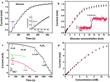 |
| | Fig. 6 (a) Amperometric response of the Mn3O4/3DGF composite electrode at 0.4 V upon the successive addition of 1 mM and 100 μM glucose (inset). (b) Calibration curve of the composite material-based glucose sensor. The inset shows the current response of the composite electrode toward the addition of 10 μM glucose. (c) Amperometric response of the Mn3O4/3DGF composite electrode toward successive addition of H2O2 at 0 V. (d) The calibration curve of the Mn3O4/3DGF electrode for H2O2. | |
Table 1 Comparison of the analytical performance of various nonenzymatic glucose biosensorsa
| Sensing material | Sensitivity (μA mM cm−2) | Detection limit (μM) | Linear range | Ref. |
|---|
| MWCNT: multi-walled carbon nanotubes. |
|---|
| Co3O4 nanofiber | 36.25 | 0.97 | Up to 2.04 mM | 48 |
| Co3O4/3DGF | 3390 | 0.025 | Up to 80 μM | 27 |
| NiO/MWCNT | 436 | 160 | Up to 12 mM | 49 |
| MWCNT | 4.36 | 1 | 2 μM–11 mM | 50 |
| Porous Au | 11.8 | 5 | 2–10 mM | 51 |
| Mesoporous Pt | 9.6 | — | 0–10 mM | 52 |
| Pd/SWCNT | 160 | 0.2 ± 0.05 | 0.5–17 mM | 53 |
| Pt–Pb alloy/MWCNT | 17.8 | 1.8 | Up to 11 mM | 54 |
| Pt–Ni alloy/graphene | 20.42 | 10 | Up to 35 mM | 55 |
| Mn3O4/3DGF | 360 | 10 | 0.1–8 mM | This work |
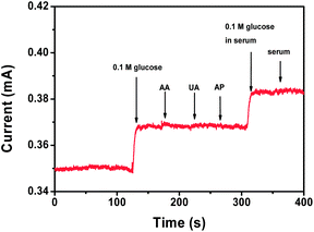 |
| | Fig. 7 Amperometric response of the Mn3O4/3DGF composite electrode toward the addition of glucose and various interferential compounds. | |
Conclusions
In conclusion, we synthesized a novel composite material of hierarchical Mn3O4/3DGF and evaluated it for enzyme-free detection of glucose and H2O2. The composite showed good flexibility and mechanical strength which enabled it to be used as a flexible and freestanding biosensor. In addition, the macro- and nanoporous structure of the composite was highly accessible to the medium that greatly facilitated the diffusion of electrolyte ions, resulting in extremely high sensitivity, large linear range, and low detection limit for the detection of both glucose and H2O2. Such high sensing performance of the biosensor could be attributed to the synergistic effect of the two nanomaterials, i.e., the electrocatalytic property of nanostructured Mn3O4 and the large surface area of 3DGF. We believe that, due to its unique structure, well-defined crystallinity and high electrochemical activity, the hierarchical Mn3O4/3DGF composite could also be beneficial to other applications, such as lithium-ion batteries and supercapacitors.Experimental section
Growth of the 3DGF network
The 3DGF was synthesized using a template-based ethanol-CVD method previously reported by us.27,56 Briefly, the nickel foam (thickness ∼0.5 mm, purchased from Alantum Advanced Technology Materials, China) was placed in the center of a quartz tube furnace and heated up to 1000 °C at a rate of 50 °C min−1. The temperature was maintained at 1000 °C for 10 min under ambient pressure with a gas flow of Ar (50 sccm) and H2 (25 sccm) in order to remove the oxide layer from the surface of nickel foam. Ethanol was then bubbled into the furnace as a carbon source by an Ar flow. The concentration of ethanol was controlled by the flow rate of Ar. After 20 minutes of growth, the sample was taken out from the furnace and rapidly cooled down to room temperature at a cooling rate of 100 °C min−1 under the protection of Ar/H2 flow (Ar![[thin space (1/6-em)]](https://www.rsc.org/images/entities/char_2009.gif) :
:![[thin space (1/6-em)]](https://www.rsc.org/images/entities/char_2009.gif) H2 = 50
H2 = 50![[thin space (1/6-em)]](https://www.rsc.org/images/entities/char_2009.gif) :
:![[thin space (1/6-em)]](https://www.rsc.org/images/entities/char_2009.gif) 25). In order to remove the nickel foam template, the as-prepared 3DGF was first dipped into the solution of 4.5% poly(methyl methacrylate) (PMMA with a molecular weight of 996
25). In order to remove the nickel foam template, the as-prepared 3DGF was first dipped into the solution of 4.5% poly(methyl methacrylate) (PMMA with a molecular weight of 996![[thin space (1/6-em)]](https://www.rsc.org/images/entities/char_2009.gif) 000) for several seconds, followed by drying at 90 °C for 1 h. After that, the PMMA coated 3DGF networks were immersed into 3 M HCl at 80 °C to etch away the nickel substrate. Finally, the PMMA layer was removed by hot acetone vapor followed by annealing at 450 °C under Ar/H2 flow.
000) for several seconds, followed by drying at 90 °C for 1 h. After that, the PMMA coated 3DGF networks were immersed into 3 M HCl at 80 °C to etch away the nickel substrate. Finally, the PMMA layer was removed by hot acetone vapor followed by annealing at 450 °C under Ar/H2 flow.Synthesis of the Mn3O4/3DGF composite and electrode fabrication
A hierarchically structured Mn3O4 network was grown on the surface of 3DGF by an electrochemical deposition method. The electrodeposition was performed using an electrochemical workstation (CHI 760D, CH instrument Inc, USA) with a conventional three-electrode system, with 3DGF as a working electrode, Pt foil as a counter electrode and Ag/AgCl as a reference electrode. Under room temperature, a constant potential of 0.5 V was applied in an aqueous solution of 0.01 mol L−1 manganese acetate for 600 s to achieve the uniform coating of MnOx on the skeleton of 3DGF. The product was then washed with double-distilled water several times and dried by ultrapure nitrogen flow. Finally, the sample was calcinated at 400 °C in air for 5 h to obtain the highly crystalline Mn3O4 on 3DGF. The composite was then affixed to a flexible PET substrate by silicon rubber to use as a freestanding electrode and a flexible biosensor.Apparatus
The surface morphology and microstructure of the sample were investigated using a field-emission scanning electron microscope (FESEM, JSM6700F, JEOL) operated at 5 kV and a transmission electron microscope (TEM, JSM2100F, JEOL) operated at 200 kV. The TEM sample was prepared by sonicating the composite material in ethanol for 3 min followed by casting one drop of the obtained dispersion on the TEM copper grid. The crystallographic information was collected by X-ray diffraction (XRD; Bruker, D8 Advance X-ray diffractometer, Cu Kα radiation, λ = 1.5406 Å). The Raman spectra were obtained with a WITeck CRM200 confocal microscopy Raman system (488 nm laser wavelength, 2.54 eV, WITeck, Germany). Thermogravimetric analysis (TGA) was conducted on a TA Instrument 2960 from 100 °C to 1000 °C under an air flow at a heating rate of 10 °C min−1.All the electrochemical tests including cyclic voltammetry (CV) and amperometry were performed in a three-electrode electrochemical cell, with the Mn3O4/3DGF composite, Pt wire and Ag/AgCl serving as working, counter and reference electrodes, respectively. 0.1 M NaOH aqueous solution was used as an electrolyte throughout the experiment.
Acknowledgements
We thank the National Medical Research Council (EDG11-may015) and Ministry of Education (AcRF tier 2, MOE2011-T2-2-010) of Singapore for the financial support.Notes and references
- J. Wang, Chem. Rev., 2008, 108, 814–825 CrossRef CAS.
- B. Xu, M.-L. Ye, Y.-X. Yu and W.-D. Zhang, Anal. Chim. Acta, 2010, 674, 20–26 CrossRef CAS.
- C. Guo, F. Hu, C. M. Li and P. K. Shen, Biosens. Bioelectron., 2008, 24, 819–824 CrossRef CAS.
- J. Liu, C. Guo, C. M. Li, Y. Li, Q. Chi, X. Huang, L. Liao and T. Yu, Electrochem. Commun., 2009, 11, 202–205 CrossRef CAS.
- P. Si, S. Ding, J. Yuan, X. W. Lou and D.-H. Kim, ACS Nano, 2011, 5, 7617–7626 CrossRef CAS.
- P. Si, P. Kannan, L. Guo, H. Son and D.-H. Kim, Biosens. Bioelectron., 2011, 26, 3845–3851 CrossRef CAS.
- K. E. Toghill, L. Xiao, M. A. Phillips and R. G. Compton, Sens. Actuators, B, 2010, 147, 642–652 CrossRef.
- J. Lu, I. Do, L. T. Drzal, R. M. Worden and I. Lee, ACS Nano, 2008, 2, 1825–1832 CrossRef CAS.
- F. Xiao, Y. Q. Li, X. L. Zan, K. Liao, R. Xu and H. W. Duan, Adv. Funct. Mater., 2012, 22, 2487–2494 CrossRef CAS.
- H. Gao, F. Xiao, C. B. Ching and H. Duan, ACS Appl. Mater. Interfaces, 2011, 3, 3049–3057 CAS.
- Y. Sun, H. Buck and T. E. Mallouk, Anal. Chem., 2001, 73, 1599–1604 CrossRef CAS.
- C.-W. Kung, C.-Y. Lin, Y.-H. Lai, R. Vittal and K.-C. Ho, Biosens. Bioelectron., 2011, 27, 125–131 CrossRef CAS.
- J. Chen, W.-D. Zhang and J.-S. Ye, Electrochem. Commun., 2008, 10, 1268–1271 CrossRef CAS.
- J. Wang, D. F. Thomas and A. Chen, Anal. Chem., 2008, 80, 997–1004 CrossRef CAS.
- D. Yu, K. Park, M. Durstock and L. Dai, J. Phys. Chem. Lett., 2011, 2, 1113–1118 CrossRef CAS.
- Q. Wu, Y. Xu, Z. Yao, A. Liu and G. Shi, ACS Nano, 2010, 4, 1963–1970 CrossRef CAS.
- C. X. Guo, H. B. Yang, Z. M. Sheng, Z. S. Lu, Q. L. Song and C. M. Li, Angew. Chem., Int. Ed., 2010, 49, 3014–3017 CrossRef CAS.
- Y. W. Zhu, S. Murali, M. D. Stoller, K. J. Ganesh, W. W. Cai, P. J. Ferreira, A. Pirkle, R. M. Wallace, K. A. Cychosz, M. Thommes, D. Su, E. A. Stach and R. S. Ruoff, Science, 2011, 332, 1537–1541 CrossRef CAS.
- S. Ding, J. S. Chen, D. Luan, F. Y. C. Boey, S. Madhavi and X. W. Lou, Chem. Commun., 2011, 47, 5780–5782 RSC.
- S. Bae, H. Kim, Y. Lee, X. Xu, J.-S. Park, Y. Zheng, J. Balakrishnan, T. Lei, H. Ri Kim, Y. I. Song, Y.-J. Kim, K. S. Kim, B. Ozyilmaz, J.-H. Ahn, B. H. Hong and S. Iijima, Nat. Nanotechnol., 2010, 5, 574–578 CrossRef CAS.
- K. S. Kim, Y. Zhao, H. Jang, S. Y. Lee, J. M. Kim, K. S. Kim, J.-H. Ahn, P. Kim, J.-Y. Choi and B. H. Hong, Nature, 2009, 457, 706–710 CrossRef CAS.
- A. Kasry, M. A. Kuroda, G. J. Martyna, G. S. Tulevski and A. A. Bol, ACS Nano, 2010, 4, 3839–3844 CrossRef CAS.
- J. D. Fowler, M. J. Allen, V. C. Tung, Y. Yang, R. B. Kaner and B. H. Weiller, ACS Nano, 2009, 3, 301–306 CrossRef CAS.
- X. C. Dong, Y. M. Shi, W. Huang, P. Chen and L. J. Li, Adv. Mater., 2010, 22, 1649–1653 CrossRef CAS.
- Y. Liu, X. Dong and P. Chen, Chem. Soc. Rev., 2012, 41, 2283–2307 RSC.
- Z. Chen, W. Ren, L. Gao, B. Liu, S. Pei and H.-M. Cheng, Nat. Mater., 2011, 10, 424–428 CrossRef CAS.
- X.-C. Dong, H. Xu, X.-W. Wang, Y.-X. Huang, M. B. Chan-Park, H. Zhang, L.-H. Wang, W. Huang and P. Chen, ACS Nano, 2012, 6, 3206–3213 CrossRef CAS.
- S. J. Chae, F. Gunes, K. K. Kim, E. S. Kim, G. H. Han, S. M. Kim, H. J. Shin, S. M. Yoon, J. Y. Choi, M. H. Park, C. W. Yang, D. Pribat and Y. H. Lee, Adv. Mater., 2009, 21, 2328 CrossRef CAS.
- T. Ramanathan, A. A. Abdala, S. Stankovich, D. A. Dikin, M. Herrera-Alonso, R. D. Piner, D. H. Adamson, H. C. Schniepp, X. Chen, R. S. Ruoff, S. T. Nguyen, I. A. Aksay, R. K. Prud'homme and L. C. Brinson, Nat. Nanotechnol., 2008, 3, 327–331 CrossRef CAS.
- A. C. Ferrari, J. C. Meyer, V. Scardaci, C. Casiraghi, M. Lazzeri, F. Mauri, S. Piscanec, D. Jiang, K. S. Novoselov, S. Roth and A. K. Geim, Phys. Rev. Lett., 2006, 97, 187401 CrossRef CAS.
- X. C. Dong, Y. M. Shi, Y. Zhao, D. M. Chen, J. Ye, Y. G. Yao, F. Gao, Z. H. Ni, T. Yu, Z. X. Shen, Y. X. Huang, P. Chen and L. J. Li, Phys. Rev. Lett., 2009, 102, 135501–135504 CrossRef.
- M. S. Dresselhaus, A. Jorio, M. Hofmann, G. Dresselhaus and R. Saito, Nano Lett., 2010, 10, 751–758 CrossRef CAS.
- X. C. Dong, D. L. Fu, W. J. Fang, Y. M. Shi, P. Chen and L. J. Li, Small, 2009, 5, 1422–1426 CrossRef CAS.
- C. M. Julien and M. Massot, J. Phys.: Condens. Matter, 2003, 15, 3151–3162 CrossRef CAS.
- D. P. Dubal, D. S. Dhawale, R. R. Salunkhe and C. D. Lokhande, J. Alloys Compd., 2010, 496, 370–375 CrossRef CAS.
- X. Kang, J. Wang, H. Wu, I. A. Aksay, J. Liu and Y. Lin, Biosens. Bioelectron., 2009, 25, 901–905 CrossRef CAS.
- T. T. Baby, S. S. J. Aravind, T. Arockiadoss, R. B. Rakhi and S. Ramaprabhu, Sens. Actuators, B, 2010, 145, 71–77 CrossRef.
- S. J. Guo, D. Wen, Y. M. Zhai, S. J. Dong and E. K. Wang, ACS Nano, 2010, 4, 3959–3968 CrossRef CAS.
- M. Pumera, A. Ambrosi, A. Bonanni, E. L. K. Chng and H. L. Poh, TrAC, Trends Anal. Chem., 2010, 29, 954–965 CrossRef CAS.
- C. S. Shan, H. F. Yang, D. X. Han, Q. X. Zhang, A. Ivaska and L. Niu, Biosens. Bioelectron., 2010, 25, 1070–1074 CrossRef CAS.
- C. S. Shan, H. F. Yang, J. F. Song, D. X. Han, A. Ivaska and L. Niu, Anal. Chem., 2009, 81, 2378–2382 CrossRef CAS.
- H. Wu, J. Wang, X. H. Kang, C. M. Wang, D. H. Wang, J. Liu, I. A. Aksay and Y. H. Lin, Talanta, 2009, 80, 403–406 CrossRef CAS.
- L. M. Lu, H. B. Li, F. L. Qu, X. B. Zhang, G. L. Shen and R. Q. Yu, Biosens. Bioelectron., 2011, 26, 3500–3504 CrossRef CAS.
- C. Z. Zhu, Y. X. Fang, D. Wen and S. J. Dong, J. Mater. Chem., 2011, 21, 16911–16917 RSC.
- L. Li, Z. Du, S. Liu, Q. Hao, Y. Wang, Q. Li and T. Wang, Talanta, 2010, 82, 1637–1641 CrossRef CAS.
- K. Schachl, H. Alemu, K. Kalcher, H. Moderegger, I. Svancara and K. Vytras, Fresenius' J. Anal. Chem., 1998, 362, 194–200 CrossRef CAS.
- Y. Lin, X. Cui and L. Li, Electrochem. Commun., 2005, 7, 166–172 CrossRef CAS.
- Y. Ding, Y. Wang, L. A. Su, M. Bellagamba, H. Zhang and Y. Lei, Biosens. Bioelectron., 2010, 26, 542–548 CrossRef CAS.
- M. Shamsipur, M. Najafi and M.-R. M. Hosseini, Bioelectrochemistry, 2010, 77, 120–124 CrossRef CAS.
- J. S. Ye, Y. Wen, W. D. Zhang, L. M. Gan, G. Q. Xu and F. S. Sheu, Electrochem. Commun., 2004, 6, 66–70 CrossRef CAS.
- Y. Li, Y. Y. Song, C. Yang and X. H. Xia, Electrochem. Commun., 2007, 9, 981–988 CrossRef CAS.
- S. Park, T. D. Chung and H. C. Kim, Anal. Chem., 2003, 75, 3046–3049 CrossRef CAS.
- L. Meng, J. Jin, G. X. Yang, T. H. Lu, H. Zhang and C. X. Cai, Anal. Chem., 2009, 81, 7271–7280 CrossRef CAS.
- H. F. Cui, J. S. Ye, W. D. Zhang, C. M. Li, J. H. T. Luong and F. S. Sheu, Anal. Chim. Acta, 2007, 594, 175–183 CrossRef CAS.
- H. C. Gao, F. Xiao, C. B. Ching and H. W. Duan, ACS Appl. Mater. Interfaces, 2011, 3, 3049–3057 CAS.
- Y.-C. Yong, X.-C. Dong, M. B. Chan-Park, H. Song and P. Chen, ACS Nano, 2012, 6, 2394–2400 CrossRef CAS.
Footnote |
| † Electronic supplementary information (ESI) available: Photograph of the composite biosensor, interference study and stability study. See DOI: 10.1039/c2tb00073c |
|
| This journal is © The Royal Society of Chemistry 2013 |
Click here to see how this site uses Cookies. View our privacy policy here. 


![[thin space (1/6-em)]](https://www.rsc.org/images/entities/char_2009.gif) :
:![[thin space (1/6-em)]](https://www.rsc.org/images/entities/char_2009.gif) H2 = 50
H2 = 50![[thin space (1/6-em)]](https://www.rsc.org/images/entities/char_2009.gif) :
:![[thin space (1/6-em)]](https://www.rsc.org/images/entities/char_2009.gif) 25). In order to remove the nickel foam template, the as-prepared 3DGF was first dipped into the solution of 4.5% poly(methyl methacrylate) (PMMA with a molecular weight of 996
25). In order to remove the nickel foam template, the as-prepared 3DGF was first dipped into the solution of 4.5% poly(methyl methacrylate) (PMMA with a molecular weight of 996![[thin space (1/6-em)]](https://www.rsc.org/images/entities/char_2009.gif) 000) for several seconds, followed by drying at 90 °C for 1 h. After that, the PMMA coated 3DGF networks were immersed into 3 M HCl at 80 °C to etch away the nickel substrate. Finally, the PMMA layer was removed by hot acetone vapor followed by annealing at 450 °C under Ar/H2 flow.
000) for several seconds, followed by drying at 90 °C for 1 h. After that, the PMMA coated 3DGF networks were immersed into 3 M HCl at 80 °C to etch away the nickel substrate. Finally, the PMMA layer was removed by hot acetone vapor followed by annealing at 450 °C under Ar/H2 flow.