Effect of microstructure and surface impurity segregation on the electrical and electrochemical properties of dense Al-substituted Li7La3Zr2O12
Lei
Cheng
ab,
Joong Sun
Park
a,
Huaming
Hou
ac,
Vassilia
Zorba
a,
Guoying
Chen
a,
Thomas
Richardson
a,
Jordi
Cabana
ad,
Richard
Russo
a and
Marca
Doeff
*a
aLawrence Berkeley National Laboratory, Environmental Energy Technologies Division, University of California, Berkeley, CA 94720, USA. E-mail: mmdoeff@lbl.gov
bDepartment of Material Sciences and Engineering, University of California, Berkeley, CA 94720, USA
cOptics and Optoelectronics Laboratory, Ocean University of China, Qingdao 266100, China
dDepartment of Chemistry, University of Illinois at Chicago, Chicago, IL 60607, USA
First published on 11th November 2013
Abstract
Al-substituted Li7La3Zr2O12 (LLZO) pellets with a grain size of 100–200 μm and a relative density of 94% were prepared by conventional solid-state processing at a sintering temperature of 1100 °C, 130 °C lower than previously reported. Morphological features and the presence of impurities were evaluated by X-ray diffraction (XRD), scanning electron microscopy (SEM) and energy dispersive X-ray spectroscopy (EDS). Femtosecond Laser Induced Breakdown Spectroscopy (LIBS) was used to visualize the distribution of impurities. The results suggest that chemical composition of the powder cover strongly affects morphology and impurity formation, and that particle size control is critical to densification. These properties, in turn, strongly affect total ionic conductivity and interfacial resistance of the sintered pellets.
Introduction
One important challenge to the development of rechargeable batteries for large format applications such as electric vehicles is to increase their practical energy density. Successful use of lithium metal as the negative electrode would enable a very high energy density device, especially when coupled with a high capacity positive electrode such as air or sulfur.1,2 There are, however, serious safety concerns due to the extreme reactivity of metallic lithium with most liquid electrolyte solutions. The use of a solid electrolyte is considered one way to enable a metallic lithium electrode, provided that the criteria of high conductivity and chemical stability are met. Among the ceramic electrolytes that have been studied, the garnet Li7La3Zr2O12 (LLZO) is promising due to its fast ion transport (conductivity >10−4 S cm−1 at room temperature)3 and purported good chemical stability against metallic lithium.4 Two polymorphs of this material have been described. The cubic phase is reported to have an ionic conductivity two orders of magnitude higher than that of the tetragonal phase.5 High temperature synthesis (above about 1000 °C) and the presence of small amounts of Al are generally required to form the more conductive cubic LLZO phase.4,6–9 However, there have been several reports of Al-free cubic LLZO produced at lower temperatures. For example, cubic LLZO has been produced by sol–gel synthesis at 700 °C.10,11 The lattice parameters of these low temperature cubic phases are larger than the values reported for nominally Al-free cubic phases produced at high temperatures (Table 1).3,12 One possibility is that these high temperature cubic phases reported earlier actually contained Al inadvertently incorporated from crucibles or furnace linings during calcination. When Al is deliberately added during synthesis, smaller cell parameters are observed6,9 because of the substitution of the smaller Al3+ for Li+.13,14 There are, however, limits to the solubility of Al3+ in this phase. As reported by Rangasamy et al.,8 a LaAlO3 impurity formed when the Al content in LLZO was high, and La2Zr2O7 coexisted with cubic LLZO when the Li content was low. Düvel et al.15 adopted a low-temperature mechanosynthesis method and reported that for values up to x = 0.4 in Li7−3xAlxLa3Zr2O12, the products were pure cubic phase, but when x > 0.60, impurity phases formed. Based on these observations, there is an optimum compositional range of about 0.19 ≤ x ≤ 0.4 for the Al content and the lattice parameter may be used as an indication of Al incorporation and Li loss during high temperature annealing.| Reference | Synthesis method/temperature | Lattice constant | Al molar concentration | Li molar concentration |
|---|---|---|---|---|
| a * indicates nominal composition. | ||||
| 3 | Solid-state/1230 °C | 12.9682 Å | 0* | n/a |
| 12 | Solid-state/1250 °C | 12.9827 Å | 0* | n/a |
| 10 | Sol-gel/750 °C | 13.0035 Å | 0 | n/a |
| 11 | Sol-gel/700 °C | 13.0021 Å | 0 | n/a |
| 6 | Solid-state/1000 °C | 12.9751 Å | 0.19 | 6.27 |
| 9 | Solid-state/1230 °C | 12.9727 Å | 0.28 | 6.05 ± 0.25 |
Beside material crystal structure, phase purity and microstructure of the LLZO membrane are also key factors for solid electrolyte applications because of the lower overall resistance and improved mechanical integrity of phase-pure, dense membranes compared to porous structures or those containing impurities. A typical sintering procedure for LLZO called for covering pellets with powder of the same composition to inhibit lithium loss and then heating to 1230 °C for more than 30 h.3,9 The resulting pellets, however, were still not fully densified.16 This lowers the total conductivity and risks the penetration of lithium dendrites through the pores during cycling, which may lead to an electrical short or fracturing of the pellet. Longer sintering times and higher sintering temperature often result in impurity phases, which can form due to lithium loss at high temperature and Al incorporation, particularly if alumina crucibles are used. Huang et al. have reported that the cubic phase decomposes with formation of La2Zr2O7 at 1250 °C.17 LaAlO3 forms when the Al content is high and La2Zr2O7 when the Li content is low.8 However, Al-substituted LLZO pellets free of the LaAlO3 impurity, with a relative density of ∼97% and a grain size of 5–10 μm, can be prepared by hot-pressing at 1000 °C followed by annealing in air to remove residual graphite left by the die.18 Other substitutions are claimed to improve sintering. For example, Ga and Ta substituted LLZO samples were reported to densify completely at 1085 °C and 1120 °C, respectively, without sacrificing the conductivity.19,20 The grain size of the densified Ga-substituted LLZO, however, was 10 μm. In polycrystalline ceramics, large grains are desirable because they minimize the grain-boundary resistance.21,22 Murugan3 suggested that the total conductivity is half of the bulk value in LLZO, confirming the lower conductivity in the grain boundaries of the material. Ideally, dense materials with large grains are the best candidates for use as solid Li ion conductors.
In this work, we studied the effects of processing conditions on grain size and impurity formation during sintering of an Al-substituted LLZO cubic phase. We were able to sinter cubic LLZO to a relative density of 94% at a considerably lower temperature than previously reported. Particle size control was found to be critical to the densification process and growth of large grains. Furthermore, the chemical composition of the powder cover strongly affected the morphology and impurity formation in the sintered pellets. These properties, in turn, have a significant impact on the electrochemical properties.
Experimental
For the synthesis of a typical batch of Al-substituted LLZO, 2.6 g of Li2CO3 (CAS# 554-13-2 Aldrich >99.0%), 5.7 g of La(OH)3 (CAS# 14507-19-8 Alfa 99.95% REO), and 2.5 g of ZrO2(CAS# 1314-23-4 Aldrich 99%) were combined with 0.2 g of Al2O3 (Alcoa) and mixed in a zirconia jar for 30 minutes using a Spex Sample Prep 8000 M mixer/mill. No excess of lithium carbonate was used to compensate for losses during the high temperature calcination. The powder mixture was fired at 1000 °C for 12 h in a covered alumina tray in static air to form LLZO. The as-synthesized powder was ground by hand and sieved so that particles smaller than 75 μm were produced. Part of the sieved fresh LLZO powder was attrition milled with 2 mm diameter ZrO2 media in isopropyl alcohol (IPA) at 450 RPM for 2 h, dried in air and used for compacting pellets. The rest of the sieved powder was divided into several batches used to cover the pellets during sintering. For some experiments, a fresh powder bed was used. In others, powder beds were re-used after having been annealed at 1100 °C for either 6 h or 12 h during pellet processing. A summary of the powder processing is provided in a schematic shown in Fig. 1. | ||
| Fig. 1 Schematic of the LLZO powder processing. | ||
Pellets around 2 mm thick were made by cold uniaxial pressing from attrition milled fresh powders using a 3/8 inch stainless steel dye without binder. The pressed pellets were placed on and fully covered by one of the three types of LLZO powders (fresh powder, 6 h annealed and 12 h annealed) in a covered alumina tray, then fired at 1100 °C for 6 or 12 h in air. The surfaces of the sintered pellets were dry-polished using several pieces of polishing paper with grit numbers progressing from 400–800, removing a 50 μm thick layer from each surface. Dry polishing was employed to avoid contact with water or contamination from liquid polishing media. A single grain thick film of LLZO was prepared using the same procedure, simply by employing less material, but was not polished.
The sintering behavior of the LLZO pellets from room temperature up to 1100 °C was studied using a vertical dilatometer (LINSEIS L75). Powders and sintered pellets were characterized by X-ray powder diffraction (XRD) using a Bruker D2-Phaser with CuKα radiation (λ = 1.54178 Å). The pure cubic LLZO pattern was simulated using PowderCell 2.4 (W. Kraus and G. Nolze, Federal Institute for Materials Research and Testing, Rudower Chaussee 5, 12489 Berlin, Germany) based on structural parameters found in ref. 6. Surface and ion milled cross-section images of the fresh pellets were obtained by scanning electron microscopy (SEM) using a JEOL-7500F field emission microscope. Fractured cross sections were first polished and then Ar-ion milled with a JEOL cross-section polisher system. Bulk composition analyses were performed using an inductively coupled plasma optical emission spectrometer (ICP-OES, Perkin-Elmer Optima 5400).
Femtosecond (fs) LIBS was used to analyze the chemical compositions and to image impurity distributions in the pellets in 2-D. A frequency tripled (343 nm) diode-pumped Ytterbium femtosecond laser (s-pulse, Amplitude Systems) was used as the excitation source, delivering 500 fs pulses at a repetition rate of 5 Hz (pulse energy 160 μJ). The fs-laser beam was focused on the specimen surface by a UV microscope objective lens. Spatially resolved 2-D chemical imaging with LIBS was achieved by scanning the sample across 3-axes (x, y, z) with respect to the femtosecond laser beam using high-precision motorized stages. The integrated emission intensity of the LIBS emission lines for each of the locations per sample were calculated and subsequently assigned to xyz space coordinates. Neutral density filters were used to attenuate the fs-laser beam and control the exact amount of laser energy that reached the sample surface. The plasma optical emission was imaged onto an optical fiber bundle by using a UV fused silica plano-convex lens, and the fiber was directly connected to the slit entrance of a spectrometer/ICCD camera system (Acton 2150/Princeton Instruments). The gate of the ICCD camera was triggered by the fs-laser and the relative delay was controlled by the ICCD. The integrated emission intensity of the LIBS emission lines for each of the 15 × 15 × 50 locations per sample were calculated and subsequently assigned to xyz space coordinates. These were then used to construct contour maps of each layer (across the lateral plane) and depth profile contours (50 layers) across each selected plane with a depth resolution of 700 nm per layer. Home-built data processing algorithms were used for data management and spatial allocation (Matlab). ICP-OES was used to quantify the atomic ratios of Li, Zr and Al over La in the bulk material and served as a standard for LIBS for quantification purposes. Following chemical imaging, the topology of the samples was obtained using white-light interferometry (Zygo-Multiview 6K).
AC impedance measurements were obtained on dense pellets using a VMP3 multichannel potentiostat/galvanostat (Bio-Logic Science Instruments). For the experiments with blocking electrodes, a gold layer was sputtered on both sides of the pellet and Pt meshes and wires were attached and used as current collectors. For cells with non-blocking electrodes, soft metallic lithium was first spread on both sides of the dense pellet. Afterwards, the pellet was sandwiched between lithium foil disks in a Swagelok-type cell. Measurements were made at frequencies from 1 MHz to 0.1 Hz. Impedances were determined from the intercepts of the relevant capacitive arcs at the real axes in the Nyquist plots and conductivities calculated using the equation σ = (1/Z)(L/A), where Z is the impedance, L is the pellet thickness, and A is the pellet area. Typical dimensions of the pellets were around 1.5 mm thick and 8.0 mm in diameter. Activation energies were determined from the behavior of the conductivity as a function of temperature using the Arrhenius equation. One cell was cycled at ambient temperature inside an Ar-filled glove box at a constant current density of 4.6 μA for 10 cycles (2 h per cycle).
Results and discussion
Portions of the fresh powder were annealed at 1100 °C for 6 h or 12 h in an alumina crucible in air during use as a powder bed for pellet fabrication. During this treatment, it remained white in color except where it was in direct contact with the pellet. Fig. 2 shows SEM images of the fresh powder before and after annealing. Similar particle shapes and sizes (10 μm) were observed for all the samples, indicating minimal sintering during the high temperature treatment. The cubic phase was maintained after annealing, with no impurity reflections found in the XRD patterns (Fig. 3), but the peaks became sharper, suggesting improved crystallinity after annealing. The atomic ratios of Li/La and Al/La (obtained from ICP-OES measurements) and cell parameters as a function of annealing time are presented in Table 2. Theoretical values are provided for comparison. The Li/La ratio decreased and the Al/La ratio increased with longer annealing time, suggesting that lithium is lost and aluminum is incorporated from the crucible during high temperature treatment. The lattice parameter also shrank with increasing Al content, in agreement with the literature.6,9–11,20 | ||
| Fig. 2 SEM images of (a) fresh powder (b) powder annealed for 6 h, (c) and powder annealed for 12 h. | ||
 | ||
| Fig. 3 XRD patterns of fresh powder (top), powder annealed in Al2O3 crucible at 1100 °C for 6 h (second from top), powder annealed in Al2O3 crucible at 1100 °C for 12 h (second from bottom) and simulated cubic LLZO pattern simulated based on ref. 6. | ||
| Annealing time | |||
|---|---|---|---|
| 0 h (fresh) | 6 h | 12 h | |
| a * Calculated, based on ratios. Oxygen contents are estimated from charge balance considerations. | |||
| Li/La | 1.94 | 1.87 | 1.78 |
| Al/La | 0.10 | 0.11 | 0.13 |
| Zr/La | 0.64 | 0.65 | 0.65 |
| Formula* | Li5.82Al0.30La3Zr1.93O11.72 | Li5.61Al0.33La3Zr1.95O11.70 | Li5.34Al0.39La3Zr1.95O11.66 |
| Lattice parameter | 12.984(8) Å | 12.981(3) Å | 12.965(3) Å |
Particle size plays a critical role in material sintering. Generally, smaller particles have greater incentive for sintering due to larger surface area. At the same time smaller particle sizes may reduce the green body density, which leads to poor necking and may make full densification difficult. There is generally an optimal particle size for good sintering behavior in a given chemical system. We compared the sintering behavior of small and large particle sizes in the micrometer range by attrition milling the fresh powder (10 μm) to 1 μm (compare Fig. 2a and 4). No impurities were observed in the XRD pattern of the attrition-milled sample, indicating no other process occurred besides reduction of the particle size. Dilatometry profiles from 600 °C to 1100 °C for two green-body pellets, one made from the unmilled powder and another from the attrition-milled sample, are shown in Fig. 5. The pellet pressed from the attrition-milled powder shrank 15% axially, but the pellet from the unmilled powder decreased in size only 6% over this temperature range.
 | ||
| Fig. 4 SEM images of attrition milled particles. | ||
 | ||
| Fig. 5 Dilatometry sintering profiles from 600 °C to 1100 °C of pellets made from attrition milled and unmilled powders. | ||
Pellets pressed from the fresh and attrition milled powders were both covered with the 10 μm-sized fresh powder and sintered at 1100 °C for 6 or 12 h. The time frame did not have an appreciable effect on the results, and only pellets processed for 12 h will be discussed from this point on. There was no significant shrinkage observed in the pellet pressed from the 10 μm-sized powder; it was porous and poorly sintered, and it contained particles ranging from 10 to 25 μm across (Fig. 6a). Both the powder cover and the pellet remained white after the heat treatment. In contrast, after sintering, the pressed pellet made from the 1 μm-sized LLZO shrank 16%, similar to the decrease found during the dilatometry experiments. The density of this pellet was 94% of the theoretical value, and it contained 100–200 μm-sized grains of regular geometric shapes (Fig. 6b). The color of the pellet and the powder cover directly above and below changed color to ivory, while the rest of the powder remained white, suggesting a surface chemical reaction. Fig. 6c presents a cross-section of a well-sintered pellet after Ar-ion milling. A few small pores are visible, but they are isolated and closed within each grain. (The irregular appearance of the top layer is due to the re-deposition of sputtered material during ion milling.) Clearly, modifying the particle size has a big effect on the sintering behavior of LLZO and can be used effectively to decrease the temperature at which densification occurs. These results show that it can be lowered more than 100 °C than previously reported for conventional methods.3,9,16,17 By using these 1 μm particles, we were also able to make free-standing dense films that are only one grain thick (150–200 μm). Fig. 6d shows a fractured cross-section of one of these. This is significant because solid ion-conducting layers in real devices must be very thin to allow reasonably high currents to pass. This shows that thin films of cubic LLZO can be prepared without having to resort to exotic and expensive techniques.
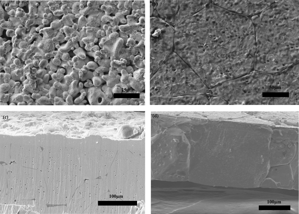 | ||
| Fig. 6 (a) Pellet made using unmilled fresh powder, (b) pellet made from the attrition milled powder, (c) Ar-ion milled cross section of a pellet made from the attrition milled powder, and (d). Cross-section produced by fracturing a single-grain thick film made from attrition milled powder. | ||
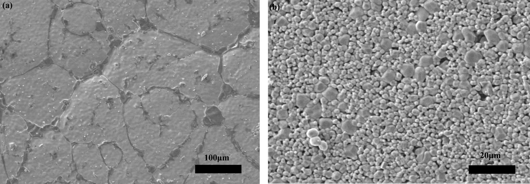
We also observed differences in the morphologies of pellets sintered with powder covers previously subjected to thermal treatments. For these experiments, pellets compacted from attrition-milled (1 μm average size) fresh powder were all sintered in 10 μm-sized fresh, or annealed (6 or 12 h) powder covers at 1100 °C for 12 h. As discussed above, the pellets under fresh powder cover were successfully densified. The one prepared using the powder annealed for 6 h was also well sintered, with a grain size (100–200 μm) similar to that of the pellet sintered in fresh powder cover (Fig. 7a). However, there appeared to be a phase preferentially segregated at grain boundaries on the surface, which showed a darker contrast than that the bulk of the grains. SEM-EDS spectral imaging of the two densified pellets are provided in Fig. 8a and b. For the pellet sintered in fresh powder (Fig. 8a), the elements were mostly uniformly distributed, although a few randomly distributed pockets enriched in Al were observed on the surface of grains. The mapping of the pellet sintered in the powder that was annealed for 6 h (Fig. 8b), however, revealed that the dark contrast phase at the grain-boundaries was rich in Al but low in La and Zr; this was probably LiAlO2 (see Discussion below).
 | ||
| Fig. 7 SEM images of the pellets sintered in (a) 6 h annealed (b) 12 h annealed LLZO powder covers. | ||
 | ||
| Fig. 8 EDS spectral imaging of (a) a pellet sintered in fresh power cover (b) a pellet sintered in 6 h annealed power cover. | ||
In contrast to these two samples, the pellet sintered in the powder annealed for 12 h was porous, with a particle size of only 1–2 μm (Fig. 7b). There was some grain coarsening, but the majority of the particles experienced minimal growth overall. Since mechanical integrity and electrochemical properties are generally poor in porous pellets, the electrochemical properties of this pellet were not studied. Thus, in addition to reducing the reaction with the Al2O3 crucible and mitigating lithium loss at high temperature, the powder cover can dramatically affect the morphology of sintered pellets, depending on its thermal history. Given that all three powder covers consisted of cubic LLZO (with slight lattice parameter variations) and had similar particle sizes (10 μm), this phenomenon must be attributable to the differences in the chemical compositions, in particular, Li and Al contents.
Fig. 9 compares the XRD patterns of the pellets sintered at 1100 °C using the different powder covers, before and after polishing. An extra reflection at 32° is observed for pellets sintered in fresh powder. This is tentatively assigned to Li2Al0.5La0.5O4 (PDF#040-1167).15 The very weak reflection peak at 21° is attributed to Li2ZrO3 (PDF# 016-0263). In contrast, Al-rich impurities LiAlO2 (PDF# 018-0714) and LaAlO3 (PDF# 085-1071) were observed in the pellets sintered in the powder covers annealed for 6 h or 12 h. In all cases, polishing removed the impurities, leaving behind cubic LLZO that appeared to be phase-pure from the XRD patterns. This result suggests that Al rich impurity phases tend to form at the pellet surface in the powder covers with low Li and high Al content, probably by inter-diffusion. The lattice parameter (Table 3) of the pellet sintered in the fresh powder cover was smaller than that found for the fresh powder itself (Table 2) and did not change significantly after polishing. The pellet was ground and dissolved in nitric acid for ICP-OES analysis, after it was polished to exclude the Li2Al0.5La0.5O4 surface impurity. The composition was determined to be Li5.27Al0.31La3Zr1.96O11.52 (normalized to La) for the pellet. The Al content did not change significantly but the Li content decreased compared with the fresh LLZO powder (Table 2). The requirements for charge balance imply that the oxygen content also decreased, but this was not directly measured. This suggests that the decrease in unit cell parameter, in this case, may be due to lithium loss, and, possibly, formation of oxygen vacancies, rather than substitution of Al for Li.
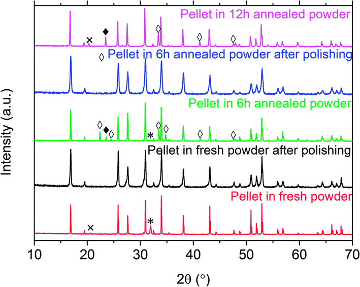 | ||
| Fig. 9 XRD patterns of a pellet sintered in fresh powder (bottom), a pellet sintered in fresh powder after polishing (second from bottom), a pellet sintered in 6 h annealed powder (third from bottom), a pellet sintered in 6 h annealed powder after polishing (second from top) and, a pellet sintered in 12 h annealed powder (top). ◊ LiAlO2 (PDF# 018-0714); ♦ LaAlO3 (PDF# 085-1071); * La2Li0.5Al0.5O4 (PDF# 040-1167); × Li2ZrO3 (PDF# 016-0263). | ||
| Parameter | Powder cover | ||
|---|---|---|---|
| Fresh powder | 6 h annealed | 12 h annealed | |
| Sintering | Densified | Densified | Not densified |
| Surface impurities | La2Li0.5Al0.5O4 | LiAlO2, LaAlO3 | LiAlO2, Li2ZrO3, LaAlO3 |
| Lattice parameter of the pellet (pre-polishing) | 12.962(7) Å | 12.967(9) Å | 12.961(6) Å |
| Lattice parameter of the pellet (post-polishing) | 12.962(2) Å | 12.966(6) Å | n/a |
| Impurity thickness | <5 μm | 15 μm | n/a |
| Conductivity (pre-polishing) | 2.3 × 10⁻⁴ S cm−1 | 1.1 × 10⁻⁴ S cm−1 | n/a |
| Conductivity (post-polishing) | 1.9 × 10⁻⁴ S cm−1 | 1.9 × 10⁻⁴ S cm−1 | n/a |
| Interfacial resistance (pre-polishing) | 540 Ohm·cm2 | 2000 Ohm·cm2 | n/a |
| Interfacial resistance (post-polishing) | 700 Ohm·cm2 | 625 Ohm·cm2 | n/a |
ICP-OES gives only the overall composition of the powder, so the interpretation of the results is complicated in the presence of secondary phases that may not be detected by XRD. In contrast, laser induced breakdown spectroscopy (LIBS) can provide detailed information on the distribution of the elements by sampling small sample volumes, thus increasing the sensitivity to small phase fractions, and allows bulk elemental mapping.23 Elemental atomic ratio maps of major (Li, La, Zr) and minor element (Al) distribution were obtained using femtosecond LIBS. The atomic lines of Li I (460.283/460.2889/460.2893 nm), La I (401.539 nm, 494.977 nm), Zr I (468.780 nm) and Al I (396.152 nm) were used for the analysis. Fig. 10 shows depth profiling (10a–c) and 2-D cross-section visualizations (10a-1–c-2) of Al, Li, and Zr contents normalized to La for two LLZO pellets, one sintered with the fresh powder and the other with the powder annealed for 6 h. The cross-section data represent maps of 1.2 mm × 1.2 mm dimensions, with 70 μm lateral resolution (spot size is 30 μm) and 700 nm per pulse resolution, to a total depth of 35 μm. The averaged atomic ratios of Li/La, Zr/La and Al/La are plotted as a function of detection depth (Fig. 10a–c) for the two pellets. The error bar at each detection depth was calculated by the standard deviation of all the points at this particular depth. A smaller error bar indicates a more uniform distribution. In the case of the pellet sintered in the fresh powder, a constant Al/La atomic ratio of 0.1 was measured from near the surface to 35 μm deep, and was higher only for the first 2 pulses (about 1–2 μm); this was the value expected for the reported composition. In contrast, Al enrichment appeared to occur at greater depths for the pellet sintered with the powder cover annealed for 6 h. The Al/La atomic ratio was highest at the surface (first 5 pulses, ∼3–5 μm) and gradually decreased with pellet depth. It was only at a depth of 20 μm that the Al/La atomic ratio approached the expected value of 0.1, as in the pellet sintered in fresh powder at depths below about 2 μm. The results agree well with the XRD data showing that the Al rich impurities (LiAlO2 and LaAlO3) were located on the surface of this sample.
 | ||
| Fig. 10 LIBS depth profiles (a–c) and cross-section imaging (a-1–c-2) of Al/La (a, a-1, and a-2), Zr/La (b, b-1, and b-2) and Li/La atomic ratios (c, c-1, and c-2) of pellets made in fresh powder and the powder annealed for 6 h. | ||
Fig. 10b and c plot Li/La and Zr/La atomic ratios as a function of depth. The two pellets both had a consistent Zr/La ratio throughout the material in contrast to the Al/La ratio. However, much higher intensities of the Li/La ratios were observed in both samples in the first 5 pulses, corresponding to a depth of about 3.5 μm. Both samples are more lithium rich on the top than expected from the impurities observed in the XRD patterns, which could be removed by polishing, implying that a very thin layer of Li2CO3 was located on the surfaces of both pellets as well.
The atomic ratios of Li/La, Zr/La and Al/La were plotted in the form of 2D cross-sections (Fig. 10a-1–c-2) to provide more details about the elemental distribution. The mappings of the Li/La and Zr/La ratios were very similar for the two different pellets and show the enrichment of Li at the surfaces. Larger differences were observed in the mapping of Al/La, however. In Fig. 10a–2, a heterogeneous Al-rich top layer about 10 μm thick was clearly visible for the pellet sintered in the powder annealed for 6 h. Al/La intensities as high as 0.7 were observed at several discrete locations on the top surface. Al-rich regions of about ∼0.4 Al/La ratios branched about 10–15 μm deep in the material with lateral distances of 150–200 μm, corresponding quite well with the interpretation that LiAlO2 was segregated at the grain-boundaries at the surface, as observed in the SEM-EDS experiment. The LIBS results suggest that the two pellets had essentially the same chemical compositions in the bulk, but differed on the surface; this is corroborated by the similarities in the lattice parameters (Table 3). The pellet sintered with fresh powder was generally more uniform than the pellet sintered in the annealed powder cover, although there was still some enrichment of Li, Zr and Al above 3 μm deep. In comparison, the pellet sintered with the powder cover annealed for 6 h had more Al containing impurities, which were segregated above a depth of about 15 μm.
AC-impedance experiments using Au (blocking) electrodes were performed on pellets sintered in fresh powder and the powder annealed for 6 h, before and after they were polished. Murugan et al. were able to resolve the bulk and grain-boundary conductivity over a frequency range from 13 MHz to 5 Hz.3 In our experiment, which was carried out from 1 MHz to 0.1 Hz, we observed one partial semi-circle at high frequency and a diffusion spike at low frequency in the Nyquist plots, and were not able to resolve bulk and grain-boundary conductivity, similar to what Buschmann et al. reported in the range from 7 MHz to 50 mHz.9 Total ionic conductivities vs. temperature are shown in an Arrhenius plot (Fig. 11) and are similar to previously reported values.3,8,9 The LLZO film that is a single grain thick (Fig. 6d) had the highest total ionic conductivity of 5.2 × 10⁻⁴ S cm−1 at 25 °C, and the activation energy was 0.29 eV. At the same temperature, the total ionic conductivity and the activation energy of the thick pellet sintered in fresh powder prior to polishing were 2.3 × 10⁻⁴ S cm−1 and 0.37 eV, respectively. This strongly implies that the room temperature ionic conductivity and activation energy of the bulk is higher than it is in the grain-boundaries, because the concentration of grain boundaries is much lower in the thin sample than in the thick pellet. The room temperature conductivities varied somewhat with the conditions used to process the pellets (Table 3). For example, the conductivity of the pellet sintered in fresh powder actually decreased slightly after polishing. The room temperature total ionic conductivity of the pellet processed in the annealed powder was only half the value of that of the pellet processed in fresh powder but it increased to 1.9 × 10⁻⁴ S cm−1 after the surface layer was polished away, the same as the value for the pellet sintered in fresh powder and polished. This indicates that the surface layer has some influence on the total ionic conductivity depending on its chemical composition.
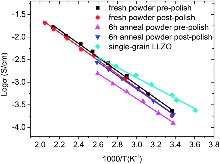 | ||
| Fig. 11 Total ionic conductivities of pellets prepared in fresh powders or those annealed for 6 h, before and after polishing. Also shown is data for the single grain LLZO film similar to that shown in Fig. 6d. | ||
The surface impurities also affected the behavior of the interfaces with lithium electrodes. Fig. 12a and Table 3 show that there were large differences in the area specific resistances of symmetric cells containing samples sandwiched between lithium foils, depending on the pellet history. In the Nyquist plots derived from the AC experiments at room temperature with zero bias on these cells, two semi-circles appeared. The first semi-circles were partial, appeared in the 1 MHz to 0.1 Hz frequency range, and corresponded to the total conductivities of the pellets measured in cells with blocking electrodes. The second semi-circles appeared at lower frequency ranges and can be assigned to the interfacial resistance.9,24 Because there are two interfaces, the value derived from the intercept with the Zre axis was divided in half for Table 3. The interfacial resistance of the pellet made in fresh powder prior to polishing was nearly four times less than that of the one processed in the annealed powder. After polishing, however, the two pellets showed very similar values. The higher interfacial resistance observed before polishing the pellet sintered in the annealed powder was most likely associated with the presence of the LaAlO3 and LiAlO2 surface impurities. This is not surprising, since these are not expected to be good lithium ion conductors. Differences in surface roughness of the pellets, which affect the contact with the lithium electrodes, may also influence the interfacial impedances that are observed and may account for differences seen between the polished and unpolished pellets.
 | ||
| Fig. 12 Nyquist plots of symmetrical cells containing thick pellets sandwiched between lithium electrodes. The plot on the left shows data for pellets processed in fresh or annealed powders before polishing and the one on the right shows the results after the pellets were polished. | ||
The value of 540 Ohm·cm2 observed for the unpolished pellet processed in the fresh powder is among the lowest interfacial impedances ever observed for an LLZO sample. One report gave a value of 2800 Ohm·cm2 for a LLZO pellet doped with 0.9 wt% Al in contact with lithium electrodes,9 and resistances close to 6000 Ohm·cm2 were seen for Ga-doped LLZO/Li interfaces.19 The lowest lithium/solid electrolyte interfacial resistance of 530 Ohm·cm2 was achieved in a full thin film solid state battery using Nb-substituted LLZO as the electrolyte, LiCoO2 as the cathode, and metallic lithium as the anode,25 and is very close to what we observed.
To evaluate the cycling stability and DC behavior, symmetrical Li/LLZO/Li cells were assembled and subjected to galvanostatic charge and discharge (Fig. 13), using a thick pellet processed in fresh powder without polishing. Based on the voltage response to a constant current of 4.6 μA cm−2 and the geometry of the pellet, a total area specific resistance of 2380 Ohm·cm2 was estimated. This value is consistent with the AC impedance measurement, and includes contributions from the bulk and both interfaces. The good match between the AC and DC results implies that the majority of current carriers are lithium ions and that the electronic conductivity of LLZO is negligible under these conditions.
 | ||
| Fig. 13 Galvanostatic cycling of a symmetrical cell with lithium electrodes and LLZO sintered in fresh powder at current density of 4.6 μA cm−2. The LLZO pellet used for this experiment was approximately 1.5 mm thick and 8.0 mm in diameter and was processed in fresh powder without polishing. | ||
The cycling profile of the symmetrical cell resembled a square wave, as is expected for a single ion conducting electrolyte. Furthermore, no increase in voltage or other significant change in the response was seen over 10 cycles, corresponding to 20 hours. This indicates that LLZO is reasonably stable against lithium metal under these conditions. To establish the good stability of LLZO definitively, however, more stringent experiments with thinner samples and over longer periods of time will need to be carried out. Our future work on LLZO will be directed towards understanding and optimizing the electrochemical behavior of this promising solid Li ion conductor, with the goal of being able to use it in real devices.
Conclusions
By decreasing the particle size, we successfully sintered cubic Al-substituted LLZO to a relative density of 94% at 1100 °C, the lowest temperature reported using conventional ceramic processing techniques. The microstructure, composition, and distribution of minor impurities in the pellets are strongly influenced by the thermal history of the powder cover used for processing. These factors, in turn, impact the total conductivity and interfacial behavior of the pellets in contact with lithium electrodes. The best results were obtained on samples made from a powder with an average particle size of 1 μm, which were heated for 12 hours in a fresh LLZO powder bed. These specimens had large grains about 100–200 μm across and few pores, all of which were closed. Using the same processing conditions, it was also possible to fabricate a freestanding thin film only a single grain thick (∼150 μm). This sample exhibited the highest total conductivity (5.2 × 10⁻⁴ S cm−1 at 25 °C) because fewer grain boundaries were present than in the thicker pellets. AC and DC experiments are consistent with the interpretation that LLZO is a single ion conductor and that it has negligible electronic conductivity. Symmetrical cells with lithium electrodes and a thick LLZO pellet as electrolyte could be cycled without noticeable deterioration in performance over 10 cycles for 20 hours, suggesting good stability of LLZO against lithium.Acknowledgements
This work was supported by the Assistant Secretary for Energy Efficiency and Renewable Energy, Office of Vehicle Technologies and the Chemical Sciences, Geosciences, and Biosciences Division, Office of Basic Energy Sciences of the U.S. Department of Energy under contract no. DE-AC02-05CH11231. The work of VZ was supported by the U.S. Department of Energy, Small Business Innovation Research Programs Office through Applied Spectra, Inc. This document was prepared as an account of work sponsored by the United States Government. While this document is believed to contain correct information, neither the United States Government nor any agency thereof, nor the Regents of the University of California, nor any of their employees, makes any warranty, express or implied, or assumes any legal responsibility for the accuracy, completeness, or usefulness of any information, apparatus, product, or process disclosed, or represents that its use would not infringe privately owned rights. Reference herein to any specific commercial product, process, or service by its trade name, trademark, manufacturer, or otherwise, does not necessarily constitute or imply its endorsement, recommendation, or favoring by the United States Government or any agency thereof, or the Regents of the University of California. The views and opinions of authors expressed herein do not necessarily state or reflect those of the United States Government or any agency thereof or the Regents of the University of California.References
- G. Girishkumar, B. McCloskey, A. C. Luntz, S. Swanson and W. Wilcke, J. Phys. Chem. Lett., 2010, 1, 2193 CrossRef CAS.
- X. Ji, K. T. Lee and L. F. Nazar, Nat. Mater., 2009, 8, 500 CrossRef CAS PubMed.
- R. Murugan, V. Thangadurai and W. Weppner, Angew. Chem., 2007, 119, 7925 CrossRef.
- M. Kotobuki, K. Kanamura, Y. Sato and T. Yoshida, J. Power Sources, 2011, 196, 7750 CrossRef CAS.
- J. Awaka, N. Kijima, H. Hayakawa and J. Akimoto, J. Solid State Chem., 2009, 182, 2360 CrossRef.
- C. A. Geiger, E. Alekseev, B. Lazic, M. Fish, T. Armbruster, R. Langner, M. Fechtelkord, N. Kim, T. Pettke and W. Weppner, Inorg. Chem., 2011, 50, 1089 CrossRef CAS PubMed.
- Y. Shimonshi, A. Toda, T. Zhang, A. Hirano, N. Imanishi, O. Yamamoto and Y. Takeda, Solid State Ionics, 2011, 183, 48 CrossRef.
- E. Rangasamy, J. Wolfenstine and J. Sakamoto, Solid State Ionics, 2012, 206, 28 CrossRef CAS.
- H. Buschmann, J. Dolle, S. Berendts, A. Kuhn, P. Bottke, M. Wilkening, P. Heitjans, A. Senyshyn, H. Ehrenberg, A. Lotnyk, V. Duppel, L. Kienle and J. Janek, Phys. Chem. Chem. Phys., 2011, 13, 19378 RSC.
- H. Xie, J. A. Alonso, Y. Li, M. T. Fernandez-Diaz and J. B. Goodenough, Chem. Mater., 2011, 23, 3587 CrossRef CAS.
- I. Kokal, M. Somer, P. H. L. Notten and H. T. Hintzen, Solid State Ionics, 2011, 185, 42 CrossRef CAS.
- J. Awaka, A. Takashima, K. Kataoka, N. Kijima, Y. Idemoto and J. Akimoto, Chem. Lett., 2011, 40, 60 CrossRef CAS.
- H. Buschmann, S. Berendts, B. Mogwits and J. Janek, J. Power Sources, 2012, 206, 236 CrossRef CAS.
- A. A. Hubaud, D. J. Schroeder, B. Key, B. J. Ingram, F. Dogan and J. T. Vaughey, J. Mater. Chem. A, 2013, 1, 8813 CAS.
- A. Düvel, A. Kuhn, L. Robben, M. Wilkening and P. Heitjans, J. Phys. Chem. C, 2012, 116, 15192 Search PubMed.
- Y. Jin and P. J. McGinn, J. Power Sources, 2011, 196, 8683 CrossRef CAS.
- M. Huang, T. Liu, Y. Deng, H. Geng, Y. Shen, Y. Lin and C. Nan, Solid State Ionics, 2011, 204, 41–45 CrossRef.
- J. Wolfenstine, J. Sakamoto and J. L. Allen, J. Mater. Sci., 2012, 47, 4428 CrossRef CAS.
- H. E. Shinawi and J. Janek, J. Power Sources, 2013, 225, 13 CrossRef.
- Y. Li, C.-A. Wang, H. Xie, J. Cheng and J. B. Goodenough, Electrochem. Commun., 2011, 13, 1289 CrossRef CAS.
- P. Knauth, Solid State Ionics, 2009, 180, 911 CrossRef CAS.
- O. Bohnke, Solid State Ionics, 2008, 179, 9–15 CrossRef CAS.
- V. Zorba, J. Syzdek, X. Mao, R. E. Russo and R. Kostecki, Appl. Phys. Lett., 2012, 100, 234101 CrossRef.
- L. Zhang, L. Cheng, J. Cabana, G. Chen, M. M. Doeff and T. J. Richardson, Solid State Ionics, 2013, 231, 109 CrossRef CAS.
- S. Ohta, T. Kobayashi, J. Seki and T. Asaoka, J. Power Sources, 2012, 202, 332 CrossRef CAS.
| This journal is © The Royal Society of Chemistry 2014 |