Control of soft machines using actuators operated by a Braille display†
Bobak
Mosadegh
ab,
Aaron D.
Mazzeo
a,
Robert F.
Shepherd
ab,
Stephen A.
Morin
ac,
Unmukt
Gupta
a,
Idin Zhalehdoust
Sani
ab,
David
Lai
c,
Shuichi
Takayama
cd and
George M.
Whitesides
*ab
aDepartment of Chemistry and Chemical Biology, Harvard University, 12 Oxford Street, Cambridge, MA 02138, USA. E-mail: gwhitesides@gmwgroup.harvard.edu
bWyss Institute for Biologically Inspired Engineering, Harvard University, 60 Oxford Street, Cambridge, MA 02138, USA
cDepartment of Biomedical Engineering, University of Michigan, 2200 Bonisteel Blvd, Ann Arbor, Michigan 48109-2099, USA
dMacromolecular Science and Engineering Center, University of Michigan, 2300 Hayward St., Ann Arbor, Michigan 48109, USA
First published on 25th October 2013
Abstract
One strategy for actuating soft machines (e.g., tentacles, grippers, and simple walkers) uses pneumatic inflation of networks of small channels in an elastomeric material. Although the management of a few pneumatic inputs and valves to control pressurized gas is straightforward, the fabrication and operation of manifolds containing many (>50) independent valves is an unsolved problem. Complex pneumatic manifolds—often built for a single purpose—are not easily reconfigured to accommodate the specific inputs (i.e., multiplexing of many fluids, ranges of pressures, and changes in flow rates) required by pneumatic systems. This paper describes a pneumatic manifold comprising a computer-controlled Braille display and a micropneumatic device. The Braille display provides a compact array of 64 piezoelectric actuators that actively close and open elastomeric valves of a micropneumatic device to route pressurized gas within the manifold. The positioning and geometries of the valves and channels in the micropneumatic device dictate the functionality of the pneumatic manifold, and the use of multi-layer soft lithography permits the fabrication of networks in a wide range of configurations with many possible functions. Simply exchanging micropneumatic devices of different designs enables rapid reconfiguration of the pneumatic manifold. As a proof of principle, a pneumatic manifold controlled a soft machine containing 32 independent actuators to move a ball above a flat surface.
Introduction
One emerging class of soft machines comprises tools fabricated by molding pneumatic channels or features into elastomeric polymers;1–4 these channels provide desired actuation upon pressurization and inflation. Pneumatic actuation using air as a working fluid has many advantages in the operation of soft machines: pressurized air has low viscosity, low mass, high availability, no environmental impact, and little cost. In order to automate actuation using pneumatic technologies, computer-controlled valves are usually used to regulate the delivery of pressurized gas, and the functions provided by the valves dictate, in turn, the level of control possible for the resulting machines.This paper describes a reconfigurable manifold useful for controlling pneumatically actuated soft machines;1–7 it is composed of a computer-controlled Braille display, which provides a compact array of piezoelectric actuators, and an interchangeable micropneumatic device, which dictates the routing of pressurized fluids between inputs, outputs, and elastomeric valves. This design is based on an analogous use of a Braille display by Takayama et al. to control aqueous flows in microfluidic systems.8
Microfluidic devices can be designed to actuate elastomeric valves pneumatically to perform on-chip pumping and routing of fluids.6,7,9–12 Because they are reliable, and can accommodate a wide range of pressures and flow rates, banks of computer-controlled solenoid valves are the most commonly used controllers for multi-channel pneumatic systems.2,3,6 With this approach, reconfiguring interconnections among valves to enable different functions is difficult. This difficulty becomes progressively greater as the number of solenoid valves increases.
There are several methods to reduce the number of external solenoid valves needed to control a large number of pneumatic outputs, and these methods can be classified into three categories: i) parallel instruction, ii) serial instruction, and iii) embedded instruction.13 Serial instruction and embedded instruction are relatively new methods of control that configure elastomeric valves to have functions similar to those of electronic logic gates and/or of the feedback loops that control fluid flow.14,15 The benefit of these methods is that the number of external valves does not scale with the number of addressable outputs for a given device. The design of such devices to operate effectively, however, remains difficult.
Parallel instruction, the most commonly used form of control for microfluidics, uses a set of solenoid valves to control a set of elastomeric valves directly.6,10,11 This form of control is intuitive to design, and provides the fastest actuation, since there are no time-dependent steps between the solenoid and elastomeric valves. Although multiplexing schemes increase the number of elastomeric valves addressed by a given set of solenoid valves, most approaches only address a single set at a given time.10,11 The most advanced scheme addresses 8953 independent outputs with only 10 control lines by using elastomeric valves that are responsive to different levels of pressure, and thus require additional external valves.11 Similarly, schemes addressing several sets of valves in parallel require additional solenoid valves, and suffer from time-delays due to consecutive actuation steps.9 Control of elastomeric valves, with or without multiplexing schemes, would therefore benefit from a pneumatic manifold with many outputs, and ideally one that would deliver several different regulated levels of pressure.
Soft robots achieve complex motion and functionality (e.g., grasping, mobility, and camouflage) by passing fluids (i.e., gases or liquids) into channels embedded in elastomers with anisotropic mechanical responses.1–3,16–22 The basic mechanism of actuation is programmed pneumatic inflation of a series of elastomeric chambers. Simple fabrication, portability, low cost, resistance to damage, and the ability to use an environmentally benign working fluid (pressurized air) as a source of power, all also contribute to the rapid adoption of pneumatic actuation in soft robots.2,3,19,20,22 Although a wide range of movements is possible using a limited number of actuators, or even a single actuator, more sophisticated motions require additional (e.g., >10) independently controlled inputs. Soft robots in some senses are similar to microfluidic systems, in that they use solenoid valves for regulation of pressurized gas to each actuator. Soft robotics, therefore, may benefit from control systems previously developed for other complex microfluidic devices.5–7,14,15,23–27 One such control system uses a computer-controlled Braille display to control the flow of liquids.8
A Braille display provides dynamic tactile information (particularly from computers) for blind individuals by using arrays of piezoelectric actuators to lift pins above a flat surface. Each pin of a standard Braille display provides a force of ~0.18 N, a maximum stroke (i.e., vertical displacement) of ~0.7 mm, and a response time of ~25 ms. The Braille pins, when lifted by the piezoelectric actuators, can close an elastomeric valve in a polydimethylsiloxane (PDMS) microfluidic device to control the flow of liquid, a system shown previously to be useful for automated cell culture.8,28,29 This Braille-based cell-culture system, however, is not directly applicable for pneumatic actuation of soft machines since it depends on peristaltic pumping of liquids (~nL min−1) through microchannels (with heights of 30 μm) with high resistance to liquid flow.
To achieve higher flow rates (~L min−1), we designed a micropneumatic device (i.e., a microfluidic device filled with pressurized gas) with larger elastomeric valves to control the delivery of pressurized gas. This paper describes micropneumatic devices with different networks of valves, fabricated using both single- and multi-layer soft lithography.30,31 As a proof-of-principle, we also designed and fabricated a soft machine that controlled the movement of a ball on an elastomeric substrate by moving and directing it with a series of pneumatically inflated “nudges”. We believe the Braille-based pneumatic manifold will promote the development of sophisticated, pneumatically actuated soft machines.
Materials and methods
Computer-controlled Braille display
The commercially available Braille display (SC9 module, KGS America) has 64 individually addressable pins, each with a diameter of 1.3 mm and a pitch of 2.4 mm. This Braille display can receive its commands and power through a universal serial bus (USB) via a custom circuit board-based controller (see Fig. S1† and Table S1† for details);28,29 other commercially available Braille displays (e.g., Ninepoint Systems, VisionCue, Freedom Scientific) are available with differing numbers of pins and modes of communication (e.g., Bluetooth), but all the pins have a similar response time, force, and stroke.Custom software and data acquisition
A custom-written LabVIEW program systematically controlled the sequence of actuating Braille pins while simultaneously recording any data provided by a pressure transducer (Digi-Key Part #480-1920-ND, Thief River Falls, MN) and a flow sensor (D6F-P0010A1, Omron, Mansfield, TX). To acquire the analog-based electrical signals from these transducers, we used a data acquisition device (USB-6210, National Instruments, Austin, TX) connected to a laptop via a USB cable. The LabVIEW software enabled rapid modification of code for addressing the varying inputs of a particular micropneumatic design by containing three hierarchical levels of code. The top level provides the user with control options directly corresponding to the inputs and outputs of the micropneumatic device. The intermediate level contains algorithms converting the user inputs into a time-sequence of binary “on” and “off” states for each of the 64 pins. The lowest level of code works with the Braille drivers to control the actuation of the Braille pins.Fabrication of micropneumatic devices
We used standard soft lithography to fabricate the micropneumatic devices and a high-resolution 3D printer (Objet Connex500) to create the master. Briefly, the height and width for the pressurizing and venting/vacuum channels were both 1 mm; the channels over the Braille pins were semi-ellipses with a width of 0.5 mm and a height of 0.1 mm, unless otherwise specified. We enlarged the molds by a factor of 1.008 to compensate for the shrinking of PDMS (Dow Corning Sylgard 184) during curing, and to ensure the channels would align to the Braille pins. We mixed PDMS using a 1![[thin space (1/6-em)]](https://www.rsc.org/images/entities/char_2009.gif) :10 ratio (cross-linker:polymer) and baked at 65 °C for at least 4 hours. PDMS membranes were fabricated by spin coating (1500 rpm for 60 seconds for a thickness of 30 μm, and 200 rpm for 60 seconds for a thickness of 200 μm) uncured PDMS on a silanized (tridecafluoro-1,2,2-tetrahydrooctyl-1-trichlorosilane) glass slide and baking at 80 °C for at least 1 hour.
:10 ratio (cross-linker:polymer) and baked at 65 °C for at least 4 hours. PDMS membranes were fabricated by spin coating (1500 rpm for 60 seconds for a thickness of 30 μm, and 200 rpm for 60 seconds for a thickness of 200 μm) uncured PDMS on a silanized (tridecafluoro-1,2,2-tetrahydrooctyl-1-trichlorosilane) glass slide and baking at 80 °C for at least 1 hour.
The slave manifold—the device in Fig. 4—consists of three layers of thick (3 mm) PDMS with embedded channels, and one thin (30 μm) membrane made of a mixture of PDMS and Ecoflex 10 using a 1:2 ratio (PDMS:Ecoflex 10). We bonded these layers by oxidizing the surface using a plasma etcher (SPI PPII, West Chester, PA) for 30 seconds,32 and then we bored holes through the top layer using a dermal biopsy punch (Harris Uni-Core, Hatfield, PA) with a diameter of 0.75 mm. Finally, we used Tygon tubing (0.7 mm ID) connected to a 20-gauge blunt needle (Techni-tool, Worcester, PA) to connect with the micropneumatic device.
Ball manipulation demonstration
The soft machine in Fig. 6 contains two elastomeric layers replicated from masters produced using a 3D printer. The mold for the top layer consists of an array of posts (diameter of 6.5 mm diameter, height of 5 mm, and a center-to-center spacing of 9 mm). The material of the top layer is Ecoflex 30 mixed with crystal violet to generate a purple color. The top wall of the Ecoflex 30 chamber is the thinnest (~2 mm) and therefore preferentially expands upon pressurization. We bonded the layer of Ecoflex 30 to a featureless bilayer of PDMS and Ecoflex 30 using silicone glue (Elastosil E951, Wacker, Adrian, Michigan). The Ecoflex 30 in the bi-layer enabled bonding to the silicone glue and the PDMS layer provided a stiffer substrate than Exoflex 30, for easier handling. We then punched 1 mm holes into the chambers of the soft machine to insert tubing from the pneumatic manifold. The soft machine rested on a commercially available bottomless 96-well plate.Results and discussion
Using the Braille display as a pneumatic manifold
We required three components for our Braille-based pneumatic manifold: i) a holder to interface the pins of the Braille display with the elastomeric valves of the micropneumatic device, ii) a set of elastomeric valves to control the flow of pressurized gas, and iii) a network of connecting channels to route pressurized gas within the micropneumatic device.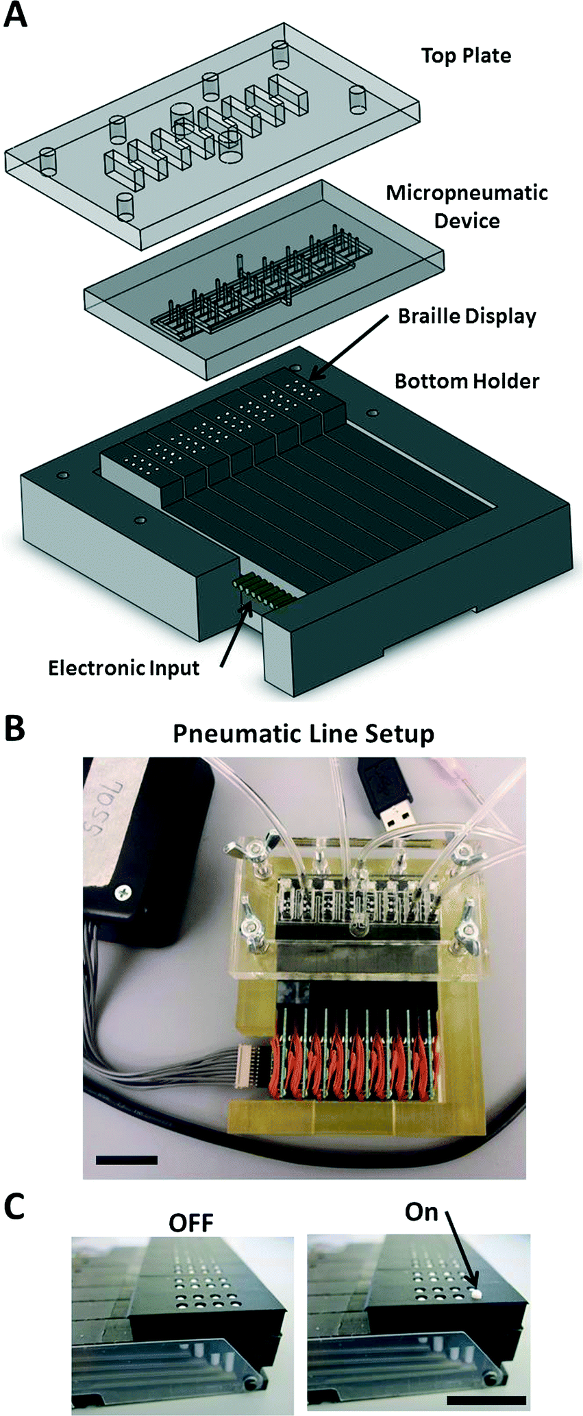 | ||
| Fig. 1 Braille manifold setup. A) Braille display in a custom holder interfaced with a micropneumatic device. B) Image of the Braille setup with five connected tubes (one pressure input, four of the 32 available output tubes) and USB controller circuit connected. Scale bar: 2 cm. C) Perspective view of the Braille display in both an off and on state in which the single Braille pin elevated 700 μm. Scale bar: 1 cm. | ||
As with elastomeric valves for microfluidic systems, we used channels with rounded cross-sectional profiles to allow the membrane to contact the entire interior surface of the channel; square-channel geometries with sharp corners are more difficult to seal completely.6 A high-resolution (16 μm) 3D printer (Objet Connex 500) created the molds with curved-channel features. We tested whether a Braille pin could completely block channels with different cross-sections by measuring the flow rate for input pressures ranging up to 60 psi (414 kPa) (Fig. S2†). The elastomeric valves we tested used three different types of membranes: i) PDMS with a thickness of 200 μm, ii) PDMS with a thickness of 30 μm, and iii) a mixture (2:1) of Ecoflex 10 and PDMS with a thickness of 30 μm. We measured the elastic moduli of these composite membranes for different mixing ratios of Ecoflex 10 and PDMS (Fig. S3†) and found, empirically, that a mixing ratio of 2:1 (Ecoflex:PDMS) resulted in a membrane capable of fully blocking a channel and maintaining a bond to another layer of PDMS, after oxygen plasma treatment.
Among the several elastomeric valves that functioned properly (i.e., could be opened and closed repeatedly), the valve achieving the maximum flow rate of air (~1 L min−1, P = 15 psi, 103 kPa) through a channel had a cross-sectional shape of a semi-ellipse (e.g., the half of an ellipse along the major axis), with a width of 1 mm, a height of 0.25 mm; this valve used a 30 μm-thick composite membrane. The valve holding the highest pneumatic pressure (60 psi, 414 kPa) had a cross-sectional shape of a semi-ellipse with a width of 0.5 mm, a height of 0.05 mm, and used a 200 μm-thick PDMS membrane. The flow rates through the valves are dependent on their proper alignment over the Braille pins and the pressure with which the micropneumatic device is pressed against the Braille pins.
One design of a network of channels for a micropneumatic device (referred to as the “master manifold”) has 32 outputs, and each connects to two separate inputs through two elastomeric valves (Fig. 2). One input connects to a source of pressure and the second input connects to the atmosphere. The actuation of the individual pins of the Braille display closes each of the 64 elastomeric valves in the PDMS manifold. Closing one of the two valves connects the outlet to either a source of pressure or a vent, and closing both of the valves holds the pressure of the outlet (for tens of minutes). The timing of the actuation of the Braille pins is pre-loaded using a script written in a text file, or dictated in real-time by selecting buttons on a graphical user interface of the LabVIEW software.
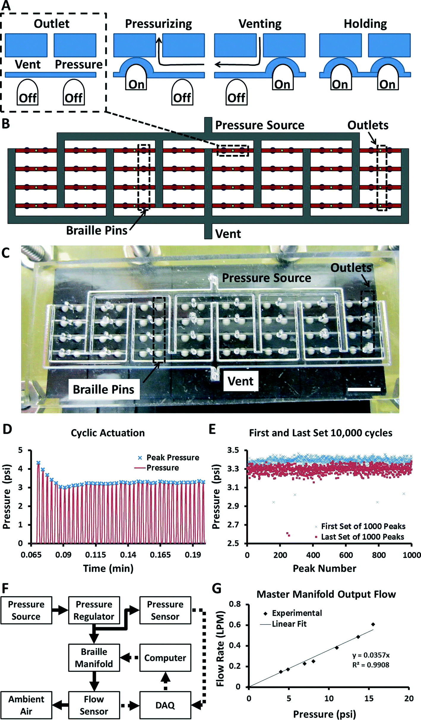 | ||
| Fig. 2 Micropneumatic device. A) The circuit comprises 32 subunits consisting of two Braille pins and one outlet. Four different states are possible depending on the combination of Braille pins actuated. B) Schematic of the PDMS device with 32 independently addressable outputs (yellow circles) fed from a single pressure source via small rounded microchannels (red) and large square channels (white). C) Actual image of the PDMS device interfaced with the Braille display. Scale bar: 5 mm. D) Pressure profile (red line) of a single output actuated at 5 Hz (peaks are marked with blue crosses). E) Comparison of first and last set of 1000 peaks of a test of 10000 cycles. F) Schematic of experimental setup for determining fluidic resistance of a single flow path through the pneumatic manifold. G) Flow rates of pressurized air for a range of pressures for a master manifold with 32 outputs. The slope of the linear fit provides the inverse of the fluidic resistance. | ||
To establish that the Braille pin would close the elastomeric valve reproducibly over many cycles, we performed a 10000-cycle quality test (Fig. 2D, E). The test measured the pressure of an output programmed to switch between 5 psi (34 kPa) and atmospheric pressure (Fig. 2D). We averaged the peak pressure for the first and last 1000 cycles of the 10000-cycle run (Fig. 2E). Although there was a statistically significant difference of 0.1 psi (0.7 kPa) between the two averages, this difference is, however, only a 3% change from the original values. The points below the mode value of the output pressure is due to the sticking of the Braille pin to the membrane of the micropneumatic device. This may be overcome by permanently attaching the Braille pin to the piezoelectric actuator so that the Braille pin is actively pulled downward to release from the membrane of the micropneumatic device (currently the pin falls due to gravity).
We conclude that these would probably outlive the soft machines that they actuated in most immediately plausible applications.
Characterization of a single output
To characterize the performance of the master manifold, we measured a range of flow rates, the response time of the Braille pins, and the ability of the Braille pins to maintain an outlet at a given pressure. Fig. 2G shows a plot relating the pressure at the input port to the flow rate at the output port. For this experiment, we used elastomeric valves with a cross-sectional geometry of a semi-ellipse, with a width of 0.5 mm and a height of 0.1 mm. The connecting tube between the flow sensor and the Braille manifold was 37 cm long with an inner diameter (I.D.) of 2.5 mm (Fig. 2F). The slope of the linear regression plot represents the inverse of the fluidic resistance of the channel network. The measured fluidic resistance for a single output of the Braille manifold, including connected tubing, is 28.0 psi LPM−1 (1.16 × 10¹⁰ kg s−1 m−4), which yields flow rates greater than 0.5 L min−1 for pressures above of air 15 psi (103 kPa).We measured the response time for equilibration of pressure for various actuation times by connecting a pressure sensor directly to a single output of the Braille display (Fig. S5A†). In this setup, the regulator provided a constant pressure of 10 psi (69 kPa), and the output port of the master manifold connected directly to the pressure sensor using Tygon tubing with I.D. of 0.7 mm and length of 20 cm. Fig. S5A† shows the pressure profiles for a single outlet alternated between the pressurizing and venting states shown in Fig. 2A with six different durations for the pressurizing state. The relatively small volume and rigid material of the tubing was responsible for the rapid (<100 ms) equilibration of pressurizing and venting pressures. Pressurization of softer objects, or objects having larger volumes, such as those commonly found in soft robotics, would generate profiles of pressure with smaller slopes than those shown here.
Results from the previous experiment demonstrated appropriate switching between the pressurizing and venting states. To test the performance of the holding state, we continuously measured the pressure of an outlet equilibrated to 10 psi (69 kPa), set the outlet to the holding state, and manually switched the pressure of the input on and off using an external valve. If the holding state operated correctly, the measurement of the output should have been unaffected by the fluctuation in the pressure of the input. Fig. S5B† shows measurements of one input and three outputs taken simultaneously. Outlets connected to sensors 3 and 4 functioned properly (i.e., were not affected by the change in the pressure of the input). While these outputs worked properly, passive leaking of gas through the elastomeric material (PDMS is quite permeable to non-polar gasses33) caused the outputs to depressurize slowly (it took ~10 min for the output to decline to ~50% of its original pressure). The output connected to sensor 2 shows perturbation in pressure since the elastomeric valves were improperly aligned over the Braille pins. Viewing the Braille pins under a magnifying glass or stereoscope can improve alignment of the micropneumatic device to avoid faulty elastomeric valves.
Control of multiple outputs
The ability to address many outputs, in parallel, from a single input of pressure, is one advantage of the master manifold. We demonstrated this ability by switching between the pressurizing and venting states of different outputs, while measuring their pressures (Fig. 3A). Specifically, we measured four outputs that alternate sequentially between a single source of pressure (i.e., a tank of pressurized air) set at 10 psi (69 kPa) and atmospheric pressure. The four outputs of the system had little cross-talk; this observation suggests that the elastomeric valves segregate the outputs into distinct flow paths. The repeatability of the pressures for each output also suggests that both sources of pressure (i.e., the tank of pressurized air and the atmosphere) supplied gas at a sufficient rate that the response times of the valves were not limited by the mass transport of air through the manifold.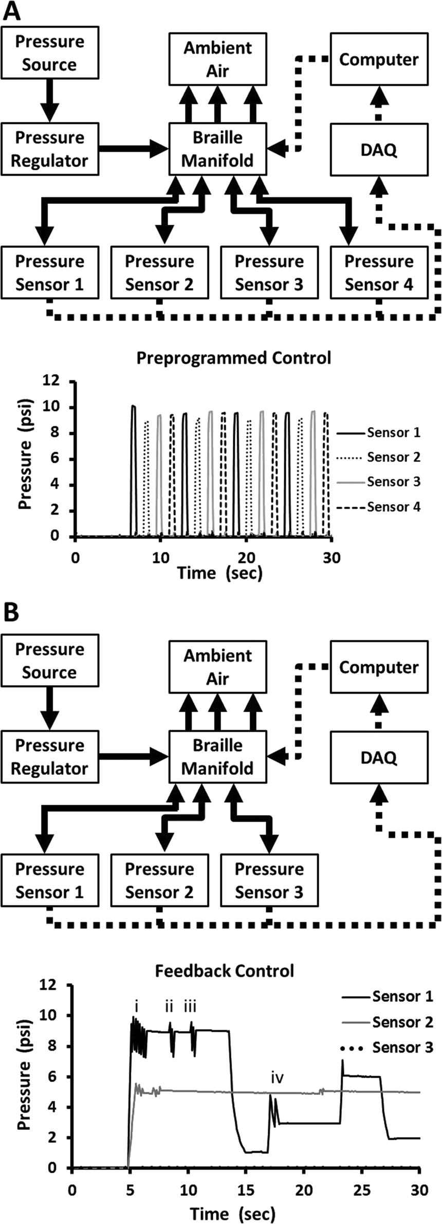 | ||
| Fig. 3 Independent output control. A) Flow diagram of experimental setup and corresponding pressure readings from four of the 32 outputs of the Braille-based pneumatic manifold when actuated using a pre-programmed timing sequence. B) Flow diagram of experimental setup and corresponding pressure readings from three outputs programmed with a feedback control loop so the Braille pins change states in order to reach a desired pressure. The pressure for output 1 changes between pressure values of 0, 9, 1, 3, 6, and 2 psi (0, 62, 7, 21, 41, and 14 kPa); the other two outputs hold a constant value of 5 psi (34 kPa) and 0 psi (0 kPa). The same source of pressure (10 psi, 69 kPa) pressurized all outputs. | ||
To demonstrate the ability of the system to actuate many objects pneumatically, we visualized the output of the system by inflating an array of 32 balloons (Fig. S6†). We connected each balloon to the master manifold using a 1 mL pipette tip, tubing, and a blunted stainless steel needle (Fig. S6A, B†). Movie S1† illustrates the range of dynamic control available with this system, including independent and parallel actuation, and inflating/venting/regulating pressure control.
Use of pressure sensors for controlled pressurization
The demonstrations we have described thus far only switch between the pressure of the input and the pressure of ambient atmosphere. In principle, however, each output can hold any pressure between these two levels. We achieved this control by regulating the duration an outlet is in the pressurizing, venting, and holding states. To determine the duration of each state, we implemented a feedback loop consisting of software, Braille manifold, and pressure sensors. The software uses a simple algorithm that changes the state of the outputs based on the values of pressure sensors. The algorithm dictates: i) if the pressure at the outlet is lower than the set pressure (within a desired range), then the output is switched to the pressurizing state, ii) if the pressure at the outlet is higher than the set pressure (within a desired range), then the output is switched to the venting state, and iii) if the pressure at the outlet is within the desired range of pressure, then the output is switched to the holding state.To demonstrate the performance of the feedback loop, we measured the pressures of three outputs, each set to a different pressure (Fig. 3B). The pressures for output 1 were changed dynamically by entering different values into the software in real-time, and the other two outputs were kept at 0 psi and 5 psi (34 kPa) to show they were unaffected by the changes occurring in the first output. The data for output 1 contained four short periods of oscillation in pressure (three oscillations when the outlet is at 9 psi (62 kPa) and one oscillation when the outlet is at 3 psi (21 kPa)). There are two reasons for these periods of oscillation: i) the first oscillation at 9 psi (62 kPa) occurred due to an inability of the feedback loop to respond more quickly than the change in pressure of the tubing (i.e., the tubing pressurizes/vents more quickly than the Braille pin can switch between states due to the small volume of the tubing, ~77 mm3). Actuation of objects with larger volumes, or objects made from more compliant materials than the tubing used, would have longer pressurization times than the response time (~100 ms) of the feedback loop, since larger volumes of gas would have to move through the valves. ii) The second and third oscillations occur because the pressure in the outlet tubing dropped below the desired value set in the software due to passive leakage of gas, reinitiating the feedback loop.
Design of manifolds with varying number of outputs
Changing how the network of channels distributes the input pressure can customize the micropneumatic device for a given application. One can vary several parameters including: i) the number of inputs, ii) the number of outputs, iii) the distribution of inputs to outputs, iv) the structure of the network of channels connecting sensors, at any point in the network, and v) the size of valves. For example, to increase the flow rate at each of the outputs, the system can use larger valves, but with the limitation of operating only at lower pressures since the increased area of the valve induces a larger force on the Braille pin than valves with smaller areas. Alternatively, outputs can be combined to actuate a set of valves in parallel, and thus to decrease the overall resistance of the flow path; the tradeoff for this design would be a loss in the total number of outputs available for independent actuation (for instance, combining four sets of valves yields eight (32/4) outputs). Another variation would be the number of inputs the system could accommodate. For a given output to deliver multiple gases and/or liquids (a useful capability for microfluidic devices or soft robots utilizing many fluids), one could design channel networks to multiplex a number of inputs and outputs;2 the tradeoff, again, would be a decrease in the total number of outputs.Design of multi-layer manifolds
For all the micropneumatic devices previously described, we used single-layer soft lithographic design and fabrication,30 and the space available for channels and elastomeric valves was therefore limited by the distance between Braille pins. Multi-layer soft lithography, however, overcomes this limitation by incorporating features in layers above the Braille display; bonding additional elastomeric membranes allows for integration of elastomeric valves into any layer. Another advantage of the multi-layered design is the construction of different manifolds by simply mixing and matching layers. As an example, we constructed a manifold containing six layers (Fig. 4). The bottom two layers formed the master manifold (Fig. 2 shows the same 32-output design). The additional four layers formed another manifold, referred to as a “slave manifold”, which multiplexes four pressure inputs to eight outputs. The outputs of the master manifold actuated the additional 32 elastomeric valves in the slave manifold. We bonded the slave manifold directly to the top of the master manifold. Alternatively, we could have separated the slave manifold from the master manifold to overcome the restriction of the spacing between the Braille pins, but this would have required 32 tubes to connect the outputs of the master manifold to the pressure chambers of the slave manifold.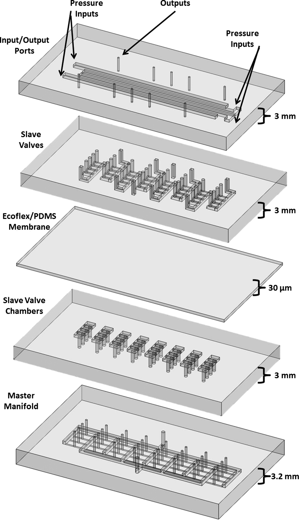 | ||
| Fig. 4 Layer-by-layer fabrication of manifolds. Schematic of the slave manifold composed of four layers bonded to the top of the master manifold. The 32 outputs of the master manifold actuate 32 chambers in the slave manifold, similar to a “Quake valve”. The Ecoflex–PDMS membrane allows large deformations to close the slave valves of 1.5 mm diameter width and 0.75 mm height. The 32 large elastomeric valves multiplex the delivery of four input pressures to eight outputs of the slave manifold. | ||
A significant advantage of the multi-layered design is larger elastomeric valves in the slave manifold (e.g., 1.5 mm wide and 0.75 mm tall) than those possible for the master manifold, since the deflection of the elastomeric membrane is independent of the stroke (0.7 mm) and size (1.3 mm in diameter) of the Braille pin. This feature enables higher flow rates that can be useful in actuation of soft machines that consist of larger volumes (>1 cm3). Fig. 5A shows a schematic of how the actuation of Braille pins controls the states of the elastomeric valves in both the master and slave manifolds. For simplicity, we show only one valve, though the device contained four valves per outlet of the slave manifold. In this configuration, the Braille pins actuate small elastomeric valves in a master manifold in a manner similar to that used in the system described previously in Fig. 2. The outputs of the master manifold directly connected to an adjacent layer containing chambers actuating a second elastomeric membrane. When the master manifold is in the pressurizing state, the second membrane actuated and closed the valve of one of the pressure inputs in the slave manifold. Alternatively, when the master manifold is in the venting state, the second membrane did not actuate; this combination allowed the valve in the slave manifold to remain open.
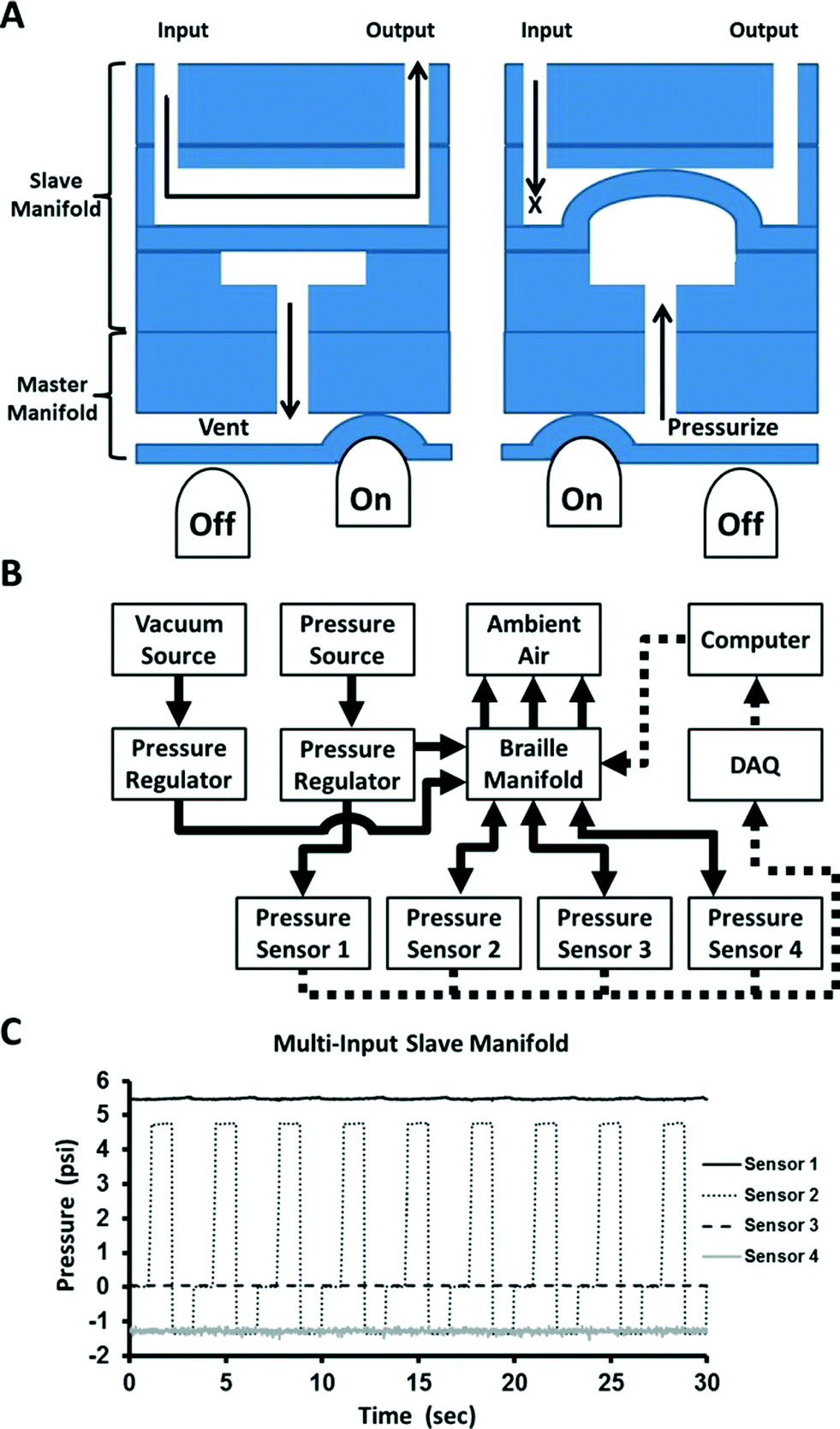 | ||
| Fig. 5 Performance of master/slave manifold. A) 2D schematic depicting a Braille pin working with a master manifold and a slave manifold for both the venting and pressurizing states. B) Flow diagram of the experimental setup consisting of three sources of pressure, the Braille system, four pressure sensors, a DAQ, and a computer. The four pressure sensors measure one of the four inputs and three of the eight outputs of the slave manifold. C) Output of a slave manifold switching among three pressure inputs. Sensor 1 was connected to one of the positive pressure inputs (data from the vacuum and atmospheric pressure input were not collected). The pressure measured at sensor 2 alternated among three of the pressure inputs, the pressure at sensor 3 was atmospheric, and the pressure at sensor 4 was the input for vacuum. | ||
The master and slave manifolds required separate sources of pressure to operate properly (Fig. 5B). The input pressure for the master manifold must be at least 5 psi (34 kPa) greater than the input pressure of the slave manifold to overcome the elastic force of the membrane and ensure proper closure of the elastomeric valves. The flow rate in the slave manifold was four times greater than the master manifold due to the larger elastomeric valves in the former (Fig. S4C†). Fig. 5C shows pressure profiles for one of the four input pressures of the slave manifold and three of the eight available outputs. We switched one output between three inputs connected to pressures of i) 5 psi (34 kPa), ii) −1 psi (−7 kPa), and iii) 0 psi (0 kPa). The input pressure and the other two outputs were unaffected by the changes in pressure of the first output; this observation demonstrates that the valves of the slave manifold functioned properly.
Using the Braille-based pneumatic manifold to manipulate objects
To demonstrate the utility of the Braille display for controlling soft machines, we made an array of 32 expandable chambers that manipulated the movement of a ball (diameter 9 mm and mass 3 g). Fig. 6A shows four chambers pressurized for different durations at ~5 psi (34 kPa) that resulted in different amounts of expansion. We programmed a series of steps to manipulate the ball on the array of chambers by timing the expansion of specific chambers in contact with the ball. First, pressurizing the four chambers surrounding the ball for 250 ms held the ball in place (Fig. 6B). Second, pressurizing the chamber to the left of the ball for an additional 250 ms caused the ball to tilt towards the right (Fig. 6C). Third, the chamber on the right of the ball was vented, allowing the ball to roll to its new position. Simultaneously pressurizing the four chambers around the new position of the ball for 250 ms stopped its movement (Fig. 6D). Lastly, the four newly inflated chambers held the ball in its new position as the remaining chambers were vented (Fig. 6E). The ball could then move in any direction using these same series of steps (Movie S2†). Although this soft machine is relatively simple, it has the potential (with some modifications), to provide haptic feedback for surgeries34 (i.e., electrical signals from instruments converted so expansion of chambers represent intensity of different signals), mechanical stimulation to biological cells28 (i.e., stretching of a membrane to induce strain on cells attached to the membrane), or sorting of object.35 Despite its simplicity, this demonstration illustrates the level of control possible using the Braille manifold and its utility for operating more sophisticated soft machines with many (>30) actuators.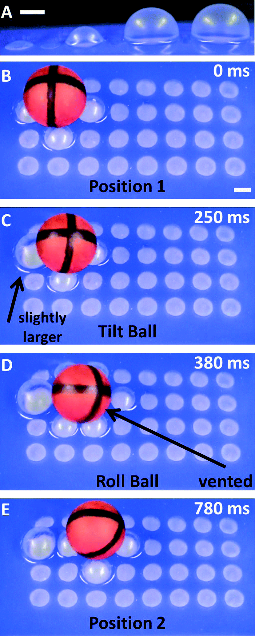 | ||
| Fig. 6 Manipulating a ball with an array of expandable chambers. A) Four chambers expanded at a constant inlet pressure of 5 psi (34 kPa) for 100 ms, 250 ms, 500 ms, 1000 ms (left to right). B–E) Time-lapse images of a ball moved to the right by systematic expansion of the chambers in the array. B) The ball held in place by four chambers expanded for 250 ms. C) The ball tilted to the right by further expanding the chamber to the left of the ball for an additional 250 ms. D) The ball rolling to the right upon venting of the chamber to the right of the ball. The four chambers around the next position of the ball expand to guide the movement of the ball. E) The ball held in place in its new position. The left-most chamber, previously used to tilt the ball, is venting. | ||
Conclusions
Pneumatically powered soft machines require control systems sophisticated enough to regulate the timing of both the pressurization and depressurization of each actuator independently. Current systems for pneumatic control, whether comprising hand-operated mechanical valves or computer-operated solenoid valves, are useful when operating a few control lines, but become too cumbersome and expensive for more advanced applications. The Braille display is a commercially available system that provides a compact array of electrically controlled actuators capable of regulating gas flows in an elastomeric microfluidic device. To develop the Braille display to be a pneumatic manifold, we incorporated mixtures of silicones with new networks of channels to meet the demands of the high flow rates required by macro-scale machines. We have shown this system can function as a pneumatic manifold by controlling up to 32 independently addressable outputs and that the multiplexing schemes are easily reconfigurable by exchanging the micropneumatic device. Moreover, the layer-by-layer design of the micropneumatic device allows an efficient means to create manifolds of greater complexity. The Braille manifold is useful in applications such as controlling elastomeric valves in microfluidic devices, actuation of pneumatic soft robots, and controlling strain layers for studies involving the stretching of cells.The current drawbacks of the Braille manifold are primarily set by the physical limitations of the hardware of the Braille display, and the material properties of PDMS. Since the commercial Braille display is optimized for providing tactile information to human fingertips, the spacing, stroke distance, and force of the pins, although useful in the commercial device we used, could be designed to accommodate larger pressures (>60 psi, 414 kPa) and flow rates (>1 L min−1) without compromising the number of available outputs. Alternatively, the use of other technologies including shape memory alloys and dielectric elastomers could, in principle, replace the piezoelectric actuators.26,36 The permeability of PDMS allows diffusion of gasses that depressurize the system when in the holding state. Other elastomers, such as polyurethanes, are less permeable, and have the potential to circumvent this issue.
We believe this system has potential to be widely useful as a portable pneumatic manifold that will be useful to provide control to medical assistive soft machines, an untethered soft robot, and complex microfluidic devices for cell culture.
Acknowledgements
The development of feedback control using pressure sensors, of layer-by-layer design to make slave manifolds, and of the soft machine for manipulating a ball was supported by the Department of Energy (DE-FG02-00ER45852), which also funded Stephen Morin. DARPA supported other parts of this work under award number W911NF-11-1-0094, and also funded Robert Shepherd and Aaron Mazzeo. We would like to thank the Wyss Institute for Biologically Inspired Engineering for providing support to Bobak Mosadegh, and the NIH (GM096040) for providing support to David Lai. We would also like to thank Nobuhiro Kato (visiting professor in the Takayama lab from Kinki University) for coding the drivers used to interface the Labview software with the Braille hardware.References
- F. Ilievski, A. D. Mazzeo, R. F. Shepherd, X. Chen and G. M. Whitesides, Angew. Chem., Int. Ed., 2011, 50, 1890–1895 CrossRef CAS PubMed.
- S. A. Morin, R. F. Shepherd, S. W. Kwok, A. A. Stokes, A. Nemiroski and G. M. Whitesides, Science, 2012, 337, 828–832 CrossRef CAS PubMed.
- R. F. Shepherd, F. Ilievski, W. Choi, S. A. Morin, A. A. Stokes, A. D. Mazzeo, X. Chen, M. Wang and G. M. Whitesides, Proc. Natl. Acad. Sci. U. S. A., 2011, 108, 20400–20403 CrossRef CAS PubMed.
- S. Wakimoto, K. Suzumori and K. Ogura, Adv. Rob., 2011, 25, 1311–1330 CrossRef PubMed.
- S. Pennathur, Lab Chip, 2008, 8, 383–387 RSC.
- M. A. Unger, H. P. Chou, T. Thorsen, A. Scherer and S. R. Quake, Science, 2000, 288, 113–116 CrossRef CAS.
- M. Zagnoni and J. M. Cooper, Lab Chip, 2010, 10, 3069–3073 RSC.
- W. Gu, X. Y. Zhu, N. Futai, B. S. Cho and S. Takayama, Proc. Natl. Acad. Sci. U. S. A., 2004, 101, 15861–15866 CrossRef CAS PubMed.
- W. H. Grover, R. H. C. Ivester, E. C. Jensen and R. A. Mathies, Lab Chip, 2006, 6, 623–631 RSC.
- D. W. Lee and Y. H. Cho, Lab Chip, 2009, 9, 1681–1686 RSC.
- D. W. Lee, I. Doh, Y. Kim and Y.-H. Cho, Lab Chip, 2013, 13, 3658–3662 RSC.
- T. Thorsen, S. J. Maerkl and S. R. Quake, Science, 2002, 298, 580–584 CrossRef CAS PubMed.
- B. Mosadegh, T. Bersano-Begey, J. Y. Park, M. A. Burns and S. Takayama, Lab Chip, 2011, 11, 2813–2818 RSC.
- B. Mosadegh, C.-H. Kuo, Y.-C. Tung, Y. Torisawa, T. Bersano-Begey and S. Takayama, Nat. Phys., 2010, 6, 433–437 CrossRef CAS PubMed.
- M. Rhee and M. A. Burns, Lab Chip, 2009, 9, 3131–3143 RSC.
- E. Brown, N. Rodenberg, J. Amend, A. Mozeika, E. Steltz, M. R. Zakin, H. Lipson and H. M. Jaeger, Proc. Natl. Acad. Sci. U. S. A., 2010, 107, 18809–18814 CrossRef CAS.
- M. S. Kim, W. S. Chu, J. H. Lee, Y. M. Kim and S. H. Ahn, IJPEM (International Journal of Precision Engineering and Manufacturing), 2011, 12, 565–568 CrossRef PubMed.
- H. Lee, C. G. Xia and N. X. Fang, Soft Matter, 2010, 6, 4342–4345 RSC.
- R. V. Martinez, J. L. Branch, C. R. Fish, L. Jin, R. F. Shepherd, R. M. Nunes, Z. Suo and G. M. Whitesides, Adv. Mater., 2013, 25, 205–212 CrossRef CAS PubMed.
- R. V. Martinez, C. R. Fish, X. Chen and G. M. Whitesides, Adv. Funct. Mater., 2012, 22, 1376–1384 CrossRef CAS.
- M. Otake, Y. Kagami, M. Inaba and H. Inoue, Rob. Auton. Syst., 2002, 40, 185–191 CrossRef.
- R. F. Shepherd, A. A. Stokes, J. Freake, J. Barber, P. W. Snyder, A. D. Mazzeo, L. Cademartiri, S. A. Morin and G. M. Whitesides, Angew. Chem., Int. Ed., 2013, 52, 2891–2896 CrossRef PubMed.
- D. J. Beebe, J. S. Moore, J. M. Bauer, Q. Yu, R. H. Liu, C. Devadoss and B. H. Jo, Nature, 2000, 404, 588–590 CrossRef CAS PubMed.
- S. M. Langelier, D. S. Chang, R. I. Zeitoun and M. A. Burns, Proc. Natl. Acad. Sci. U. S. A., 2009, 106, 12617–12622 CrossRef CAS PubMed.
- M. J. Madou, L. J. Lee, S. Daunert, S. Lai and C.-H. Shih, Biomed. Microdevices, 2001, 3, 245–254 CrossRef CAS.
- S. Vyawahare, S. Sitaula, S. Martin, D. Adalian and A. Scherer, Lab Chip, 2008, 8, 1530–1535 RSC.
- D. B. Weibel, M. Kruithof, S. Potenta, S. K. Sia, A. Lee and G. M. Whitesides, Anal. Chem., 2005, 77, 4726–4733 CrossRef CAS PubMed.
- Y. Kamotani, T. Bersano-Begey, N. Kato, Y.-C. Tung, D. Huh, J. W. Song and S. Takayama, Biomaterials, 2008, 29, 2646–2655 CrossRef CAS PubMed.
- Y. C. Tung, Y. S. Torisawa, N. Futai and S. Takayama, Lab Chip, 2007, 7, 1497–1503 RSC.
- Y. N. Xia and G. M. Whitesides, Annu. Rev. Mater. Sci., 1998, 28, 153–184 CrossRef CAS.
- J. C. McDonald, D. C. Duffy, J. R. Anderson, D. T. Chiu, H. K. Wu, O. J. A. Schueller and G. M. Whitesides, Electrophoresis, 2000, 21, 27–40 CrossRef CAS.
- M. A. Eddings, M. A. Johnson and B. K. Gale, J. Micromech. Microeng., 2008, 18, 067001–067004 CrossRef.
- T. C. Merkel, V. I. Bondar, K. Nagai, B. D. Freeman and I. Pinnau, J. Polym. Sci., Part B: Polym. Phys., 2000, 38, 415–434 CrossRef CAS.
- C. H. King, A. T. Higa, M. O. Culjat, S. H. Han, J. W. Bisley, G. P. Carman, E. Dutson and W. S. Grundfest, Stud. Health Technol. Inform., 2007, 125, 217–222 Search PubMed.
- http://www.youtube.com/watch?v=NVUx_0VN5PQ .
- A. O'Halloran, F. O'Malley and P. McHugh, J. Appl. Phys., 2008, 104, 071101 CrossRef.
Footnote |
| † Electronic supplementary information (ESI) available. See DOI: 10.1039/c3lc51083b |
| This journal is © The Royal Society of Chemistry 2014 |