Production of renewable petroleum refinery diesel and jet fuel feedstocks from hemicellulose sugar streams†
Hakan
Olcay‡§
,
Ayyagari V.
Subrahmanyam‡¶
,
Rong
Xing||
,
Jason
Lajoie**
,
James A.
Dumesic**
and
George W.
Huber**
*
Department of Chemical Engineering, University of Massachusetts, Amherst, MA 01003, USA. E-mail: huber@ecs.umass.edu; Fax: +1 413-545-1647; Tel: +1 413-545-0276
First published on 9th November 2012
Abstract
We demonstrate how hemicellulose-derived C5 sugars can be converted into a high-quality petroleum refinery feedstock by a four-step catalytic process. The substitute petroleum consists of normal, branched and cyclic alkanes up to 31 carbons in length and is similar in composition to feedstocks produced in a petroleum refinery today from crude oil. This process can be tuned to adjust the size of the liquid alkanes. In the first step furfural is produced from the acid-catalyzed dehydration of hemicellulose-derived sugar streams in a biphasic reactor. The second step is the aldol condensation of furfural with acetone in a THF solvent and using a NaOH catalyst to produce highly conjugated C13 compounds along with some oligomeric adducts formed through Michael addition reactions. These compounds are then hydrogenated with a Ru/Al2O3 catalyst forming both the fully hydrogenated form of the C13 oligomers and also forming larger oligomers by Diels–Alder reactions. The extent of Diels–Alder reactions can be tuned by changing the temperature and feed concentration, thereby adjusting the distribution of liquid alkanes that can be produced. The final step in this process is hydrodeoxygenation using a Pt/SiO2–Al2O3 bifunctional catalyst to produce the liquid alkanes. A simple biorefinery model has shown that about 55% of a furfural–acetone mixture (10![[thin space (1/6-em)]](https://www.rsc.org/images/entities/char_2009.gif) :
:![[thin space (1/6-em)]](https://www.rsc.org/images/entities/char_2009.gif) 3 wt ratio) can be converted into cycle oils while also producing other refinery products such as gasoline and natural gas.
3 wt ratio) can be converted into cycle oils while also producing other refinery products such as gasoline and natural gas.
Broader contextDepletion in fossil fuel reserves and increased concerns on the environment have accelerated advances in alternative fuels research, and particularly in biofuel production. Most biofuels, such as ethanol, are single-component fuels, and they cannot meet current engine specifications unless blended with petroleum products. Today's transportation infrastructure relies primarily on petroleum fuels which are mixtures of components. Hence, it is crucial for these fuels to be produced in an environmentally and economically sustainable way, from renewable resources. Here we show that hemicellulose-derived C5 sugars can be converted into petroleum refinery feedstocks in an integrated process where Diels–Alder reactions play an important role. These feedstocks, which are composed mainly of normal-, iso- and cyclo-paraffinic compounds, can be further processed in existing petroleum refineries to make common refinery products. These feedstocks have no olefinic or heteroatom content, and contain almost no aromaticity. This will help eliminate the expensive hydrotreatment processes downstream in the petroleum refineries, and reduce combustion-related air pollutants. The seamless integration of these feedstocks into petroleum refineries will rapidly help drive our society's move towards a renewable transportation economy by allowing us to use our existing petroleum refinery infrastructure more efficiently. |
1 Introduction
Advances are being made worldwide that allow us to more efficiently convert our renewable resources into a range of liquid transportation fuels.1–6 Most of these processes produce single-component fuels like ethanol,7 butanol,2 dimethylfuran,8 alkyl esters,9,10 and a narrow distribution of straight-chain alkanes. However, gasoline, diesel and jet engines are manufactured to be used with petroleum-derived fuels that are mixtures of compounds having a range of boiling point fractions, combustion properties, and physical properties. Furthermore, most of the previous processes produce renewable fuels that can only be used in gasoline engines. The purpose of this paper is to demonstrate a process for the production of a high-quality renewable petroleum refinery feedstock from C5 sugars that is a mixture of compounds similar in composition to streams inside the petroleum refinery today. This synthetic renewable petroleum feedstock could be seamlessly integrated into existing petroleum refinery producing jet, diesel and gasoline. This integration would allow us to use our existing petroleum refinery infrastructure more efficiently thereby allowing us to more rapidly accelerate our society's move to a renewable transportation economy.2 Unlike Fischer–Tropsch synthesis,11,12 which produces liquid fuels at costs of greater than $5 per gallon of gasoline energy equivalent, this approach does not require an expensive gasification step.In previous work, we presented a catalytic process for converting carbohydrates into liquid alkanes having carbon numbers between 7 and 15.4,13,14 This process involved four key steps: (1) dehydration of carbohydrates into furfural and 5-hydroxymethylfurfural (HMF); (2) aldol condensation reaction of furfural and HMF with acetone; (3) low-temperature hydrogenation step; and (4) high-temperature hydrodeoxygenation. We have recently demonstrated how this process can be used to convert aqueous hemicellulose stream, derived from wood, into a liquid product that is primarily tridecane (n-C13) which could be blended into jet or diesel fuels.15 These waste hemicellulose sugars are among the most inexpensive biomass feedstocks that are available today. A preliminary economic analysis has shown that tridecane could be produced at costs of less than $3.00 per gallon in a large integrated biorefinery.15 One of the drawbacks of this previous process is that only a single-component fuel is produced.
In scaling up this tridecane process we have adjusted the chemistry to produce a mixture of different hydrocarbons including n-paraffins, isoparaffins and naphthenes (cyclic alkanes) with carbon numbers from C1 to C31. The overall process is outlined in Fig. 1 and is composed of four basic steps. The first step (not shown in Fig. 1) is the production of furfural by dehydration of hemicellulose sugars. Furfural is a highly promising feedstock for biofuel production,16 and it can be produced from aqueous xylose in high yields in biphasic reactors.17 The second step is the aldol condensation of furfural with acetone producing highly conjugated C13 compounds, called furfural–acetone (2![[thin space (1/6-em)]](https://www.rsc.org/images/entities/char_2009.gif) :
:![[thin space (1/6-em)]](https://www.rsc.org/images/entities/char_2009.gif) 1) dimer (FAF), along with some oligomeric adducts. These products are then hydrogenated in the third step in the presence of supported metal catalyst. In this hydrogenation process heavy cyclic molecules are also formed by cycloaddition reactions (i.e. hydrocycloaddition). The fourth step involves the hydrodeoxygenation and isomerization over bifunctional catalysts to produce petroleum refinery feedstocks, or more specifically, fluid catalytic cracker cycle oil substitutes, having carbon numbers up to C31. We have also observed the formation of higher alkane products than C13 from furfural-derived feeds, at relatively lower yields (up to 26%), using the original integrated process described earlier.13,14
1) dimer (FAF), along with some oligomeric adducts. These products are then hydrogenated in the third step in the presence of supported metal catalyst. In this hydrogenation process heavy cyclic molecules are also formed by cycloaddition reactions (i.e. hydrocycloaddition). The fourth step involves the hydrodeoxygenation and isomerization over bifunctional catalysts to produce petroleum refinery feedstocks, or more specifically, fluid catalytic cracker cycle oil substitutes, having carbon numbers up to C31. We have also observed the formation of higher alkane products than C13 from furfural-derived feeds, at relatively lower yields (up to 26%), using the original integrated process described earlier.13,14
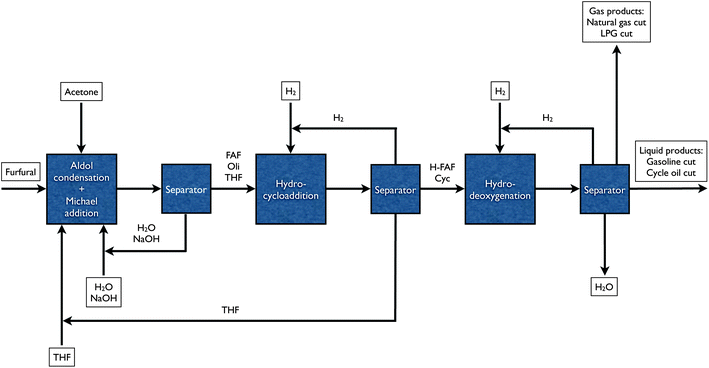 | ||
Fig. 1 Block flow diagram for the production of petroleum refinery feedstocks from furfural in an integrated biorefinery. Furfural production from hemicellulose extract through dehydration is not shown. Key: FAF – furfural–acetone (2![[thin space (1/6-em)]](https://www.rsc.org/images/entities/char_2009.gif) : :![[thin space (1/6-em)]](https://www.rsc.org/images/entities/char_2009.gif) 1) dimer (i.e. the aldol condensation product of furfural and acetone), Oli – oligomeric adducts formed by Michael addition reactions, H-FAF – hydrogenated furfural–acetone (2 1) dimer (i.e. the aldol condensation product of furfural and acetone), Oli – oligomeric adducts formed by Michael addition reactions, H-FAF – hydrogenated furfural–acetone (2![[thin space (1/6-em)]](https://www.rsc.org/images/entities/char_2009.gif) : :![[thin space (1/6-em)]](https://www.rsc.org/images/entities/char_2009.gif) 1) dimer, Cyc – cyclic compounds formed by hydrogenation and Diels–Alder reactions. 1) dimer, Cyc – cyclic compounds formed by hydrogenation and Diels–Alder reactions. | ||
The purpose of this paper is to demonstrate how this four-step process can be used to produce a petroleum refinery feedstock. We collect experimental data for each of the steps shown in Fig. 1. We show how changes in the reaction conditions in the hydrocycloaddition and aldol condensation steps can be used to tune the product selectivity. We calculate how the overall mass balances for this process in a large biorefinery could result. The data in this paper demonstrate how aqueous C5 sugar streams can be converted into mixtures of alkanes that can fit seamlessly into existing petroleum refineries.
2 Experimental
2.1 Aldol condensation
The following procedure was used for aldol condensation reactions unless otherwise indicated in the text. A 36 wt% furfural solution in tetrahydrofuran (THF) was prepared by mixing 172 cm3 of furfural (2 moles, Acros Organics) with 400 cm3 of THF (Fisher Chemical) in a 1000-cm3 glass round bottom flask. 78.6 cm3 of acetone (1 mole, Fisher Chemical) was then mixed with this solution. The reaction was started when 100 cm3 of an 8 N NaOH solution was added into the resulting mixture. The reactor contents were continuously stirred with a magnetic stir bar for one hour at room temperature. The products were then separated into organic and aqueous layers in a separatory funnel. The aqueous layer was then discarded.After the condensation reaction, the solvent of the organic layer (THF) was removed by a rotary evaporator running at 40 °C. The concentrated condensation products were either directly re-mixed with THF to obtain the exact concentration required in the next step or separated with a column chromatography to remove any larger oligomers formed during aldol condensation.
2.2 Hydrocycloaddition
The condensation products in THF were reacted under a hydrogen pressure of 5.52 MPa (800 psi) or 8.27 MPa (1200 psi) at a temperature range of 80–140 °C over a Ru/Al2O3 catalyst (2 wt% Ru; Alfa Aesar, pelletized) in a 160-cm3 batch reactor (Parr). The concentration of condensation products in THF was either 10 or 30 wt%.Prior to the reaction, the catalyst was reduced in situ under a continuous hydrogen flow (155 cm3 min−1) while being heated. The temperature was ramped from room temperature to 290 °C over eight hours and maintained at this temperature for an additional 2 hours during reduction. The feed (100 cm3) was introduced to the reactor after the catalyst had been reduced and brought to room temperature.
The reactor was then charged to the desired pressure with hydrogen, and heated to the desired temperature by a fast temperature ramping (10 minutes to reach reaction temperature) under slow stirring speed. The time zero of the reaction in this paper was recorded once the temperature reached the set point. The stirring speed was then increased to its maximum value (i.e. 600 rpm). The reaction was carried out for 6 hours keeping the reactor pressure constant by the continuous addition of hydrogen to maintain a constant hydrogen pressure. Liquid samples were collected periodically.
After the experiment was complete, the reactor was quenched in an ice bath. The contents were removed and filtered through a THF-resistant glass microfiber filter paper (Whatman) removing the catalyst.
Hydrocycloaddition reactions were also conducted using a mixture of condensation products with furfural (Acros Organics) or furfuryl alcohol (Acros Organics) as feed.
2.3 Hydrodeoxygenation
The products of the hydrocycloaddition experiments were used as feeds for the hydrodeoxygenation reactions. These reactions were carried out in an upflow packed-bed reactor. The hydrocycloadded products were first removed from their solvent (THF) by using a rotary evaporator operating at 40 °C. The resulting mixture was viscous at room temperature, and hence, 10 wt% methanol was added to enable its continuous flow into the reactor. The reaction of 90 wt% hydrocycloadded products in methanol was carried out at 300 °C at 8.27 MPa (1200 psi) over a bifunctional Pt/silica–alumina catalyst (4%, SiO2![[thin space (1/6-em)]](https://www.rsc.org/images/entities/char_2009.gif) :
:![[thin space (1/6-em)]](https://www.rsc.org/images/entities/char_2009.gif) Al2O3 = 4). The liquid and hydrogen flow rates were 0.02 cm3 min−1 and 155 cm3 min−1, respectively.
Al2O3 = 4). The liquid and hydrogen flow rates were 0.02 cm3 min−1 and 155 cm3 min−1, respectively.
The feed was supplied to the reactor by an HPLC pump (Varian Prostar 210). The organic feed was then mixed with hydrogen and entered a 6.35 mm (1/4′′) OD tubular stainless steel reactor. The reaction occurred over the catalyst packing fixed between two end-plugs of glass wool (Fisher) inside the reactor. The reactor was heated by a tubular split furnace (Lindberg). A back-pressure regulator (Swagelok) was used to keep the reactor pressure constant. The liquid reactor effluent was collected in a 150-cm3 sample cylinder (Swagelok). The gaseous products were analyzed with an on-line gas chromatograph (GC). Liquid products were drained from the sample cylinder periodically and analyzed off-line. The drained samples were first separated into aqueous and organic layers. Aqueous layers were discarded, and the organic layers were analyzed in the GC.
The 4% Pt/silica–alumina catalyst was prepared by incipient wetness method in a 10-gram scale. The platinum salt, tetraammineplatinum(II) nitrate (Strem Chemicals, 0.795 g), was dissolved in distilled water (11.1 cm3). The resulting solution was then added drop wise to the silica–alumina powder (Davison SIAL 3125, silica-to-alumina ratio = 4, 9.6 g) while mixing continuously. The catalyst was dried in an oven at 110 °C for 3 h. The dried catalyst was then calcined under an airflow of 300 cm3 min−1 at 290 °C for 2 hours following a 3-hour ramp from room temperature. Prior to reaction, the catalyst was reduced in situ at 450 °C for 2 hours following a 7-hour temperature ramp under hydrogen flow of 155 cm3 min−1.
Hydrodeoxygenation reactions were also conducted using a pure tridecane feed (Acros Organics) at a temperature range of 250–350 °C.
2.4 Analytical techniques
All the liquid products were separated by an Agilent HP-5 capillary column (50 × 0.32 × 0.17) and analyzed by a flame ionization detector in a Shimadzu GC-2010 gas chromatograph. Identification of certain components in the liquid samples was done by analysis in a Shimadzu GC-2010 Plus GC-MS system equipped with a Restek Rtx-VMS capillary column (30 × 0.25 × 1.40).Gel Permeation Chromatography (GPC) studies were done on the products of aldol condensation and Michael addition reactions using a Shimadzu HPLC system equipped with a Varian MesoPore column and an UV detector (at 254 nm). Samples were prepared for GPC by dissolving the condensation products in stabilized tetrahydrofuran which also constitutes the mobile phase. The GPC column was standardized using polystyrene molecular weight standards in the range of 162 to 38![[thin space (1/6-em)]](https://www.rsc.org/images/entities/char_2009.gif) 640 Da. The molecular weights of these products determined by GPC are the polystyrene equivalent molecular weights.
640 Da. The molecular weights of these products determined by GPC are the polystyrene equivalent molecular weights.
On-line gas analyses for the hydrodeoxygenation reactions were done by a dual-oven Shimadzu GC-2014 gas chromatograph. The gas samples were simultaneously injected into an Agilent GS-GasPro packed column (15 × 0.32) and a Restek ShinCarbon ST 100/120 micropacked column. Components in the gas samples, after being separated in these columns, were analyzed by flame ionization and thermal conductivity detectors, respectively.
Carbon, hydrogen and oxygen elemental analyses of the organic samples were done by Galbraith Laboratories at Knoxville, TN. Water content of the organic layers of the hydrodeoxygenation products was determined using a Mettler-Toledo V20 volumetric Karl-Fischer titrator. The carbon content of the aqueous layers of the same products was measured by a Shimadzu 5000A total organic carbon analyzer.
Hydrocarbon typing analyses to determine the overall concentrations of n-paraffins, isoparaffins, cyclics and aromatics of the organic hydrodeoxygenated products were done by Triton Analytics Corporation at Houston, TX. These analyses were performed by a GC-MS technique called Nitric Oxide Ionization Spectroscopy Evaluation (NOISE).18
The boiling range distribution of these organic hydrodeoxygenated products as well as the hydrocycloadded products was determined by a Shimadzu GC-2010 High Temperature Simulated Distillation gas chromatograph.
Functional groups in the condensation and hydrocycloaddition products, and the changes in these groups during hydrocycloaddition reactions were determined by Nuclear Magnetic Resonance (NMR) studies on a Bruker AVANCE-400 spectrometer and Attenuated Total Reflectance Infrared Spectroscopy (ATR-FTIR) studies using a Bruker Alpha ATR Spectrometer.
3 Experimental results
3.1 Reaction overview
The reaction pathway for the formation of these renewable petroleum feedstocks is shown in Fig. 2.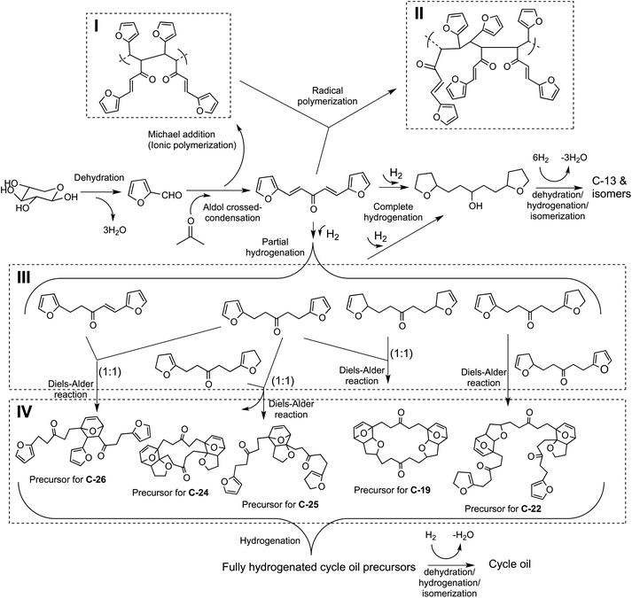 | ||
| Fig. 2 Reaction pathways for conversion of C5 sugars to petroleum refinery feedstocks. (I) Oligomers formed by Michael addition reaction along with the aldol condensation products. (II) A representative structure that can be obtained via radical polymerization of the FAF when it is stored in the absence of any solvent over a period of time. (III) Partial hydrogenation products of FAF. (IV) Representative products of Diels–Alder reactions of the partially hydrogenated compounds. Note that the Diels–Alder mechanism involving the oligomers of (I) and (II) is not shown. | ||
The unframed section of this figure shows how xylose can be converted into a C13 alkane, tridecane, and its isomers. Xylose is first converted into furfural through a dehydration step. Furfural is then reacted with acetone through a carbon–carbon coupling reaction in an aldol condensation step to form a precursor molecule with 13 carbons. The subsequent hydrogenation and hydrodeoxygenation steps help saturate the carbon–carbon double bonds in the structure and remove oxygen from the molecule in the form of water.
The numbered sections (also called as routes in the rest of the text) present the formation of representative compounds from the reactions that are significant for cycle oil production. Sections I, II and IV demonstrate other examples of carbon–carbon coupling reactions. Michael addition reactions shown in Section I take place during aldol condensation reaction, the products of which can undergo radical polymerization over time producing more oligomeric compounds like the one given in Section II. Section IV presents examples of Diels–Alder reactions that can occur during the hydrogenation step. The compounds that can undergo such reactions include the oligomeric molecules of Sections I and II, and the partially hydrogenated compounds as shown in Section III.
The details of the reactions shown in Fig. 2 are explained in the following sections along with the experimental outcomes for each step.
3.2 Step 1: dehydration
The first step in this process is the dehydration of xylose to furfural. In this paper we will use pure furfural as the starting material for the aldol condensation experiments as we have already demonstrated that aqueous hemicellulose streams can be converted into furfural in a continuous flow reactor in yields of 90% of the theoretical yield.19 Solid acid catalysts could also be incorporated into this process to further reduce the cost of furfural production.203.3 Step 2: aldol condensation and Michael addition
The second step in this process is aldol condensation where furfural reacts with acetone with a NaOH catalyst in a biphasic reactor21 to form furfural–acetone (2![[thin space (1/6-em)]](https://www.rsc.org/images/entities/char_2009.gif) :
:![[thin space (1/6-em)]](https://www.rsc.org/images/entities/char_2009.gif) 1) dimer (FAF, or simply, D) in a tetrahydrofuran (THF) solvent. The furfural conversion in these reactions was 100%. The FAF can oligomerize forming heavier products by Michael addition reaction in the presence of NaOH as shown by Route I in Fig. 2. This polymerization is initiated by the intermediate and side product, furfural–acetone (1
1) dimer (FAF, or simply, D) in a tetrahydrofuran (THF) solvent. The furfural conversion in these reactions was 100%. The FAF can oligomerize forming heavier products by Michael addition reaction in the presence of NaOH as shown by Route I in Fig. 2. This polymerization is initiated by the intermediate and side product, furfural–acetone (1![[thin space (1/6-em)]](https://www.rsc.org/images/entities/char_2009.gif) :
:![[thin space (1/6-em)]](https://www.rsc.org/images/entities/char_2009.gif) 1) monomer (FA) (see Fig. S1 in ESI† for mechanism). These reactions take place via C–C bond formation between an alpha carbon of an FAF molecule and a beta carbon of another FAF (positioning is with respect to the carbonyl group). Based on the GPC analyses done on the aldol condensation products, the oligomeric adducts formed through Michael addition reactions have mainly 3 or 4 FAF units in their structures (Fig. 3).
1) monomer (FA) (see Fig. S1 in ESI† for mechanism). These reactions take place via C–C bond formation between an alpha carbon of an FAF molecule and a beta carbon of another FAF (positioning is with respect to the carbonyl group). Based on the GPC analyses done on the aldol condensation products, the oligomeric adducts formed through Michael addition reactions have mainly 3 or 4 FAF units in their structures (Fig. 3).
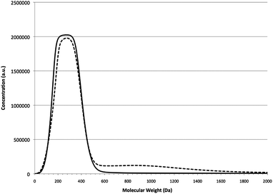 | ||
| Fig. 3 GPC chromatograms of the purified (solid line) and crude (dashed line) FAFs. Molecular weights shown are polystyrene-equivalent molecular weights. Note that the molecular weight of FAF is 214 g mol−1. | ||
Fig. 3 shows the GPC chromatograms of the purified (via column chromatography) and crude aldol condensation products. The region between 40 and 540 Da corresponds to the FAF. The region above 500 Da corresponds to the oligomeric adducts. Between 13 and 16% of the final product is composed of these oligomeric compounds depending on the stirring speed used for aldol condensation. The product compositions from aldol condensation reactions for the purified and crude aldol condensation products are reported in Table 1. The heavies (Hf) are the oligomeric adducts, and the lights (Lf) are the compounds smaller than FAF (D). The primary tool used to identify and quantify these compounds is GC analysis. These compounds have been categorized as heavies or lights based on their GC retention times relative to the FAF. Quantification is done based on the relative peak areas when pure compounds are not available to obtain a calibration curve. More information on this table is provided in Section 3.4.
| Run # | Feed | Reaction | Results | ||||||||
|---|---|---|---|---|---|---|---|---|---|---|---|
| FAF | %Feed | Feed selectivities | T (°C) | P (MPa) | %D conv. | Product selectivities | |||||
| %Dd | %Lfe | %Hff | %HDg | %Lpe | %Hpf | ||||||
a The reactions were conducted over 2% Ru/alumina catalyst in a 160-cm3 batch reactor for 6 h. The amount of catalyst used was kept the same for all runs (15 g). Total amount of feed in THF was 100 cm3. Subscripts: f for feed, p for product.
b Purified feed (i.e. purified FAF).
c Crude feed (i.e. crude FAF).
d Furfural–acetone (2![[thin space (1/6-em)]](https://www.rsc.org/images/entities/char_2009.gif) : :![[thin space (1/6-em)]](https://www.rsc.org/images/entities/char_2009.gif) 1) dimer (FAF).
e Lights (i.e. lighter compounds than FAF, Lf, or fully hydrogenated FAF, Lp, excluding THF).
f Heavies (i.e. heavier compounds than FAF, Hf, or fully hydrogenated FAF, Hp).
g Fully hydrogenated FAF (i.e. n-C13 precursor).
h Products obtained under the conditions of these runs are used as feeds to hydrodeoxygenation reactor. 1) dimer (FAF).
e Lights (i.e. lighter compounds than FAF, Lf, or fully hydrogenated FAF, Lp, excluding THF).
f Heavies (i.e. heavier compounds than FAF, Hf, or fully hydrogenated FAF, Hp).
g Fully hydrogenated FAF (i.e. n-C13 precursor).
h Products obtained under the conditions of these runs are used as feeds to hydrodeoxygenation reactor.
|
|||||||||||
| 1 | Pb | 30 | 97.9 | 1.30 | 0.838 | 110 | 8.27 | 99.8 | 51.2 | 3.85 | 44.9 |
| 2 | P | 30 | 97.6 | 1.48 | 0.907 | 80 | 8.27 | 99.8 | 56.0 | 2.08 | 41.9 |
| 3h | P | 30 | 96.5 | 1.17 | 2.28 | 140 | 8.27 | 99.9 | 35.6 | 30.9 | 33.5 |
| 4h | Cc | 30 | 83.2 | 3.77 | 13.0 | 110 | 8.27 | 99.8 | 1.32 | 7.65 | 91.0 |
| 5 | P | 10 | 95.3 | 1.37 | 3.34 | 110 | 8.27 | 99.6 | 52.5 | 18.6 | 28.9 |
| 6 | C | 10 | 80.7 | 3.27 | 16.0 | 110 | 8.27 | 99.9 | 13.1 | 3.80 | 83.2 |
| 7h | P | 10 | 96.1 | 1.41 | 2.52 | 110 | 5.52 | 99.6 | 74.7 | 7.21 | 18.1 |
| 8 | P | 30 | 96.9 | 1.07 | 1.99 | 110 | 8.27 | 99.8 | 40.0 | 12.3 | 47.8 |
Oligomerization of the crude FAF can also occur during storage if the THF solvent is removed (see Route II in Fig. 2). Fig. 4 demonstrates this oligomerization reaction. Further oligomerization, however, is prevented when THF was introduced. Such reactions do not take place when FAF is stored after being purified by column chromatography from the Michael addition products. Similar to Michael addition reactions, such radical polymerization reactions most likely proceed through the ethylene groups of the FAF structures (see Fig. S2 in ESI† for mechanism). ATR-FTIR studies on these products have revealed the presence of aliphatic C–H stretches which disappear in the spectrum of the FAF after it has been purified from the oligomers as shown in Fig. 5.
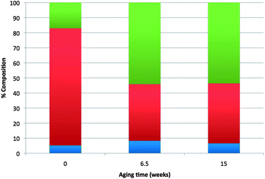 | ||
| Fig. 4 Change in composition of aldol condensation products with storage time. Key: blue – lights (smaller compounds than FAF – excluding THF), red – FAF, green – heavies (i.e. oligomers, heavier compounds than FAF). Time zero is when crude FAF was prepared. For the following 6.5 weeks it was kept at 4 °C as solid without any solvent. After that it was mixed with THF (30 wt%), and stored for an additional 8.5 weeks. | ||
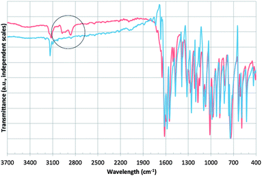 | ||
| Fig. 5 ATR-FTIR spectra of crude (red) and purified (blue) FAF. The region circled indicates the aliphatic C–H stretches. | ||
3.4 Step 3: hydrocycloaddition
The FAF produced in the aldol condensation step was hydrogenated over a Ru-based catalyst at low temperatures in a batch reactor (80–140 °C). This hydrogenation reaction was accompanied by the Diels–Alder reactions which are a type of cycloaddition reaction. Table 1 presents data for these low-temperature hydrocycloaddition reactions of purified and crude FAF at different concentrations, temperatures, and pressures. A purification step is carried out through column chromatography to remove oligomers from the feed before 6 of the 8 hydrocycloaddition runs shown in Table 1. The lights (Lp) include all the compounds smaller than the fully hydrogenated FAF (see the product of complete hydrogenation in Fig. 2) excluding THF; and the heavies (Hp) include all the hydrocycloadded compounds that are larger. Any partially hydrogenated FAF present in the products is also included in the lights. The identification, categorization and quantification of these compounds have been carried out in a similar method as used for the products of Step 2.Runs 1 and 2 compare the effect of reaction temperature on the product distribution. Increasing the reaction temperature from 80 °C to 110 °C decreases the fully hydrogenated FAF selectivity and increases the heavies concentration. Increasing the reaction temperature further to 140 °C (Runs 8 and 3) decreases the formation of heavier products while increasing the formation of light products. These light products are most likely formed as a result of cracking reactions during the formation of heavier cycloadded products. Increasing the concentration of oligomers (Hf) in the feed from 0.8% to 2.0%, as shown in Runs 1 and 8, shows only a slight increase in the heavies formation but a large increase in the lights formation. Further suppression of these cracking reactions would most likely lead to a higher heavies selectivity. Increasing the concentration of oligomers in the feed to 13% (Run 4 vs. Runs 1 and 8) demonstrates that the heavies selectivity can reach more than 90%, with the fully hydrogenated FAF selectivity remaining at ca. 1%. Thus during the low-temperature hydrogenation both the FAF molecules and oligomers undergo Diels–Alder reactions forming heavier cycloadded compounds. The oligomers, therefore, promote the formation of heavies.
Runs 5 and 8 compare the effect of total feed concentration (10% vs. 30%) on the product selectivity. The heavies selectivity increases with increasing feed concentration. This trend indicates that Diels–Alder reactions proceed homogeneously, and that increasing the feed-to-catalyst ratio will promote the cycloaddition reactions. As shown by Runs 5 and 7, decreasing the pressure from 8.27 MPa to 5.52 MPa increases the selectivity to the fully hydrogenated FAF from 52 to 75%.
Diels–Alder reactions are proposed to be the most likely reaction that forms C–C bonds during these hydrogenation reactions. Diels–Alder reactions are a [4 + 2] cycloaddition reaction between a conjugated diene and an electron-withdrawing dienophile.22 The partially hydrogenated FAFs can act as dienophiles and/or dienes promoting these reactions. We have previously shown that the FAF is hydrogenated initially through the ethylene bonds over Ru.15 This, along with the results presented above, suggests that the oligomers present in the feed can also act as dienophiles due to their already-saturated ethylene bonds from polymerization.
Reactions carried out in the absence of any catalyst and in the presence of hydrogen showed that crude FAF undergoes autocycloaddition reactions at 110 °C (see Fig. 6). Once again, this behavior indicates that cycloaddition reactions proceed homogeneously. Since there is no formation of partially hydrogenated FAFs under these conditions, the rates of these cycloaddition reactions are much lower than those carried out in the presence of a metal catalyst (i.e. when hydrogenation is also taking place). The presence of alumina or activated carbon in the reaction medium suppresses the rate of these reactions, as shown by Fig. 7 and 8, respectively.
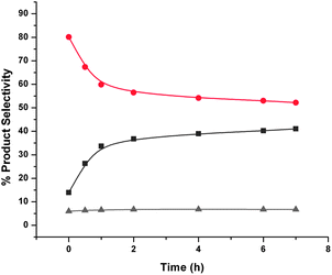 | ||
| Fig. 6 Reaction of aged crude FAF products with time without any catalyst. Key: ▲ – lights (gray), ● – FAF (red), ■ – heavies (dark gray). Cycloaddition reactions were conducted at 110 °C and 8.27 MPa (1200 psi) using 30% crude and aged feed in the presence of hydrogen and in the absence of any catalyst in a 160-cm3 batch reactor for 7 h. The time when the set temperature was reached after ramping is taken as the start of reaction (i.e., t = 0). Total amount of feed in THF was 100 cm3. | ||
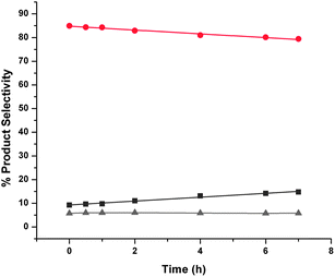 | ||
| Fig. 7 Autocycloaddition reactions of aged crude FAF products with time with alumina. Key: ▲ – lights (gray), ● – FAF (red), ■ – heavies (dark gray). Cycloaddition reactions were conducted at 110 °C and 8.27 MPa (1200 psi) using 30% crude and aged feed in the presence of hydrogen and 15 g Catapal B alumina in a 160-cm3 batch reactor for 7 h. The time when the set temperature was reached after ramping is taken as the start of reaction (i.e., t = 0). Total amount of feed in THF was 100 cm3. | ||
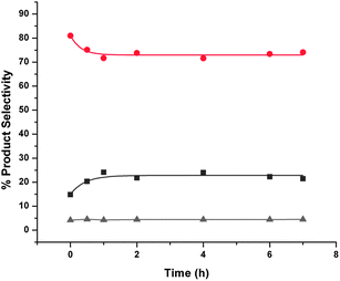 | ||
| Fig. 8 Autocycloaddition reactions of aged crude FAF products with time with activated carbon. Key: ▲ – lights (gray), ● – FAF (red), ■ – heavies (dark gray). Cycloaddition reactions were conducted at 110 °C and 8.27 MPa (1200 psi) using 30% crude and aged feed in the presence of hydrogen and 15 g activated carbon in a 160-cm3 batch reactor for 7 h. The time when the set temperature was reached after ramping is taken as the start of reaction (i.e., t = 0). Total amount of feed in THF was 100 cm3. | ||
We also studied the hydrocycloaddition of mixtures of purified FAF with furfural and furfuryl alcohol to see if furfural and/or furfuryl alcohol would become incorporated into the growing hydrocarbon products. As shown in Fig. 9, a 1![[thin space (1/6-em)]](https://www.rsc.org/images/entities/char_2009.gif) :
:![[thin space (1/6-em)]](https://www.rsc.org/images/entities/char_2009.gif) 1 mixture of furfural with purified FAF produces a 45% selectivity to heavy products. In contrast, as shown in Fig. 10, a 1
1 mixture of furfural with purified FAF produces a 45% selectivity to heavy products. In contrast, as shown in Fig. 10, a 1![[thin space (1/6-em)]](https://www.rsc.org/images/entities/char_2009.gif) :
:![[thin space (1/6-em)]](https://www.rsc.org/images/entities/char_2009.gif) 1 mixture of furfuryl alcohol with purified FAF produces a 30% selectivity to heavy products. This result suggests that the furfural becomes incorporated into the heavy products during hydrocycloaddition while furfuryl alcohol does not. This incorporation most likely occurs because furfural can form an even stronger dienophile in the reacting medium, thereby promoting cycloaddition reactions.
1 mixture of furfuryl alcohol with purified FAF produces a 30% selectivity to heavy products. This result suggests that the furfural becomes incorporated into the heavy products during hydrocycloaddition while furfuryl alcohol does not. This incorporation most likely occurs because furfural can form an even stronger dienophile in the reacting medium, thereby promoting cycloaddition reactions.
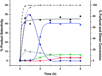 | ||
| Fig. 9 Hydrocycloaddition reactions of mixture of furfural and purified FAF with Ru/Carbon. Key: (selectivities) ▶ – tetrahydrofurfuryl alcohol (blue), ▼ – 1,2-pentanediol (green), ◆ – furfuryl alcohol (dark blue), ▲ – lights (excluding other lighter products than fully hydrogenated FAF that are indicated on the figure) (gray), ● – fully hydrogenated FAF (red), ■ – heavies (dark gray); (conversion) dotted line – furfural, dashed line – FAF. Feed selectivities are shown at time zero. Hydrocycloaddition reaction was conducted at 110 °C and 8.27 MPa (1200 psi) using furfural and purified feed (15% each) over 15 g 2% Ru/alumina catalyst in a 160-cm3 batch reactor for 6 h. The time when the set temperature was reached after ramping is taken as the start of reaction (i.e., t = 0). Total amount of feed in THF was 100 cm3. | ||
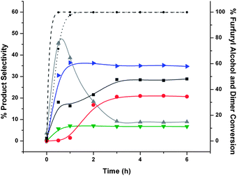 | ||
| Fig. 10 Product selectivities of hydrocycloaddition reactions of furfuryl alcohol and FAF, and their conversion with time. Key: (selectivities) ▶ – tetrahydrofurfuryl alcohol (blue), ▼ – 1,2-pentanediol (green), ▲ – lights (excluding other lighter products than fully hydrogenated FAF that are indicated on the figure) (gray), ● – fully hydrogenated FAF (red), ■ – heavies (dark gray); (conversion) dotted line – furfuryl alcohol, dashed line – FAF. Feed selectivities are shown at time zero. Hydrocycloaddition reaction was conducted at 110 °C and 8.27 MPa (1200 psi) using furfuryl alcohol and purified feed (15% each) over 15 g 2% Ru/alumina catalyst in a 160-cm3 batch reactor for 6 h. The time when the set temperature was reached after ramping is taken as the start of reaction (i.e., t = 0). Total amount of feed in THF was 100 cm3. | ||
The results suggest that during the hydrogenation step, partially hydrogenated FAF species, formed through Route III in Fig. 2, can undergo Diels–Alder (cycloaddition) reactions forming heavier compounds. Route IV in Fig. 2 demonstrates the formation of some representative structures that can form by these cycloaddition reactions. NMR analysis has shown that these species are mostly fully saturated at the end of these hydrocycloaddition reactions (see Fig. S4–S6 in ESI† for 13C-NMR spectra).
3.5 Step 4: hydrodeoxygenation
The final step in this process is hydrodeoxygenation, where hydrocycloadded products react with hydrogen removing the oxygen as water and producing the final hydrocarbon products which include straight-chain alkanes, isomers and naphthenes. Hydrodeoxygenation uses a bifunctional catalyst that contains both metal and acid sites.4,23 Dehydration reactions occur on the acid catalyst sites. Hydrogenation, decarbonylation and retro-aldol condensation reactions occur on the metal catalytic sites.Products obtained from hydrocycloaddition (Runs 7, 3 and 4 of Table 1) were fed to the hydrodeoxygenation reactor at 300 °C and 8.27 MPa. These feeds had high, medium and low concentrations of hydrogenated FAF (H-FAF), respectively (H-FAF-to-heavies ratios of 4.1, 1.1 and 0.015). The liquid products contained an organic phase and an aqueous phase. The aqueous phase was primarily water with a carbon content in ppm levels. The organic phase had less than 0.5% oxygen content. The resulting product distributions of the organic gas and liquid phases are shown in Fig. 11, as determined by simulated distillation, GC-FID, GC-TCD and NOISE analyses. The blue bars in Fig. 11 correspond to the feed with high H-FAF concentration, whereas green and red bars in this same figure correspond to medium and low H-FAF concentrations, respectively. These data were collected from runs of 6 consecutive days, after which pressure build-up was observed across the catalyst bed. Normal reactor operation was restored and catalyst activity was resumed following in situ calcination and reduction steps. The gas phase product yield was about 10% for the blue and green data, and 16% for the red data. The gas phase products included only C1–C6 alkanes except for the red data which also contained small amounts of CO2 (less than 0.5 carbon%). The liquid products range from 5 to 31 carbons in length, which are primarily either paraffinic or cyclic. The NMR spectra (see Fig. S7–S9 in ESI†) show no olefinic or aromatic content in these products. The NOISE analysis shows a small (4%) aromatic content for only the red data of Fig. 11. The products from the high H-FAF containing feed resulted primarily in C12 and C13 alkanes (60.1 wt% selectivity; blue bars in Fig. 11). Hydrodeoxygenation of the feed that contained the lowest concentration of H-FAF resulted in a wide distribution of mainly cyclic hydrocarbons from 7 to 31 carbons in length (red bars in Fig. 11). The feed that contained 36% hydrogenated FAF and 34% heavies, on the other hand, produced both C13 alkane (at 36.2 wt% selectivity) and a broad distribution of hydrocarbons after hydrodeoxygenation (green bars in Fig. 11).
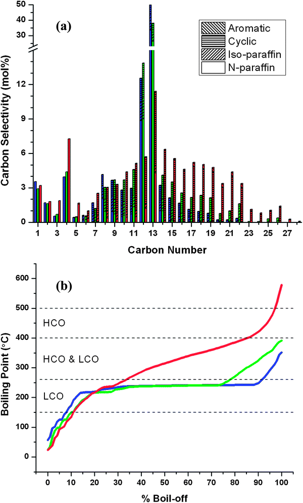 | ||
| Fig. 11 Molar carbon selectivities (a) and simulated distillation curves (b) for different renewable petroleum refinery feedstocks derived from aqueous xylose feedstocks. Boiling ranges for different petroleum feedstocks are included in (b): light cycle oil (LCO) and heavy cycle oil (HCO). These products were obtained by hydrocycloaddition and hydrodeoxygenation of condensed furfural–acetone mixtures. The conditions used to obtain the corresponding hydrocycloaddition products are given in Table 1: blue – Run 7, green – Run 3 and Red – Run 4. Hydrodeoxygenation reactions were conducted at 300 °C and 8.27 MPa over 2.5 g 4% Pt/silica–alumina catalyst. (See ESI† for tabulated data.) | ||
These results suggest that the “heavy” products observed after hydrocycloaddition react to form a broad mixture of cyclic alkanes ranging from 7 to 31 carbons in length during hydrodeoxygenation (see Fig. S3 in ESI† for detailed mechanisms). The hydrogenated FAF, in contrast, produces primarily C13 alkane. These results indicate that the hydrocarbon products produced by hydrodeoxygenation can be adjusted depending on the product that is desired. These steps are modified mainly by the inclusion of oligomerization (e.g. Michael addition) and Diels–Alder (cycloaddition) reactions.
Fig. 11b shows the simulated distillation results of the organic liquid products we produce from hydrodeoxygenation. As shown in this figure, the products that contain primarily tridecane have a narrow distillation range (blue curve in Fig. 11b) where 90% of the products boil in a boiling range of from 60 to 250 °C. The products that contain a wide distribution of hydrocarbons (red curve in Fig. 11b) have a broad boiling point range in the distillation curve. Engines and oil refineries have been designed to process fuels that are mixtures of compounds. From an engine perspective, the products that have a broad range of boiling points are preferred as opposed to those with a single compound.
These hydrocarbons produced have a carbon distribution and a boiling point range similar to feedstocks derived from crude oil including light cycle oil (LCO) and heavy cycle oil (HCO) produced from fluid catalytic cracker units in a petroleum refinery. The liquid products produced by this process could be used directly as LCO and HCO substitutes. LCO contains hydrocarbons having carbon numbers between C9 and C25 with a boiling range of 150–400 °C.25 HCO contains compounds in the range of C15–C35 having a boiling range of 260–500 °C.25 In petroleum refineries these cycle oils can be distilled into fuel cuts and blended along with other refinery streams into products such as gasoline, jet fuel, diesel fuel and fuel oil. Cycle oils can be further cracked down in a hydrocracker to increase the production of lighter fuel cuts like gasoline.26 These biomass-derived petroleum refinery substitutes have no olefinic content that would, otherwise, cause fuel instability. Furthermore, they have no heteroatoms and almost no aromatic content. These attributes will help reduce the hydrogen consumption in downstream hydrotreating processes in petroleum refineries. NOx, SOx, and particulate emissions from these fuels would also be reduced.27–30
We also studied the conversion of tridecane at similar reaction conditions used for our hydrodeoxygenation reactions, as shown in Fig. 12. Pure tridecane was converted over 4% Pt/silica–alumina catalyst in the presence of hydrogen at three temperatures: 250 °C, 300 °C and 350 °C. At 250 °C a low tridecane conversion (less than 1.4%) was observed, and the products are mainly composed of the isomers of tridecane. This result indicates that only isomerization occurs at this temperature and the reaction conditions used in this study. Increasing the temperature to 300 °C increased the extent of cracking and isomerization reactions. Twenty one percent of the products at this temperature underwent isomerization. Cracking reactions also occurred at 300 °C with 24% yield towards hydrocarbons having less than 13 carbons. Gas phase products were also observed at this temperature. Increasing the reaction temperature to 350 °C caused the cracking reactions to increase with more than 99% of the products being smaller than C13. Thirty two percent of the tridecane feed was converted into gaseous products with an overall 35% yield towards isomerization. At both 300 °C and 350 °C the main components in the gas phase were propane, butane and pentane. Isomerization reactions are crucial, because the presence of branched alkanes in hydrocarbon fuels improves the cold flow properties of the fuels.31 No alkanes larger than tridecane were observed in these runs. This result indicates that no carbon–carbon bond formation reactions occur for the alkanes during the hydrodeoxygenation process, and all the carbon–carbon bond formation occurs in either the aldol condensation or the hydrocycloaddition step.
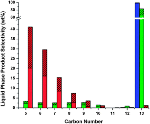 | ||
| Fig. 12 Effect of temperature on liquid product selectivity from cracking and isomerization reactions of tridecane. Key: blue – 250 °C, green – 300 °C, red – 350 °C; unshaded – n-alkanes, shaded – branched alkanes. Isocracking reactions were conducted in the presence of hydrogen at 8.27 MPa (1200 psi) with a residence time of 5.5 h in a half-inch flow reactor over 12.7 g 4% Pt/silica–alumina catalyst (packing length = 23.6 cm (9.3′′)) using a feed of pure tridecane. | ||
3.6 Overall material balances
As demonstrated in this paper, we are able to convert furfural into a high-quality petroleum refinery feedstock. Either a single hydrocarbon like tridecane or a mixture of different compounds can be produced. The overall material balances for the experiments in this study of producing different products from a mixture of furfural, acetone and hydrogen are shown in Fig. 13. This figure is based on the data obtained from all the processing steps that involve Run 4 (Fig. 13b) and Run 7 (Fig. 13a) of Table 1. Fig. 13a utilizes an FAF purification step and corresponds to optimizing the reaction conditions to maximize the tridecane production. Fig. 13b corresponds to optimizing the reaction conditions to produce a mixture of compounds. This figure assumes a 100% separation of all fractions. Both of these processes produce about the same amount of cycle oil cut while utilizing almost the same amount of hydrogen. Process (a) produces higher amounts of jet fuel cut, whereas Process (b) makes more of heavier cuts such as diesel fuel and fuel oil. Energy balances similar to those carried out elsewhere15 have indicated that these processes are not a net energy consumer.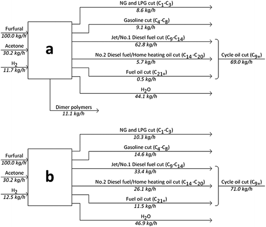 | ||
| Fig. 13 Input–output analysis for a potential biorefinery based on processing of furfural, acetone and hydrogen. Process (a) employs a purification step removing oligomers from the feed to the hydrocycloaddition reactor; whereas Process (b) utilizes them. The product distributions for (a) and (b) correspond to the blue and red data of Fig. 11, respectively. Cuts are defined based on the definitions provided by EIA24 and EPA.25 Key: NG – natural gas, LPG – liquefied petroleum gas. | ||
4 Summary and conclusions
Biomass-derived hemicellulose extracts are composed mainly of xylose molecules which are 5-carbon sugar monomers. In order for them to be converted into diesel and jet fuels, these molecules need to undergo carbon–carbon coupling reactions. One way of achieving this coupling is through the aldol condensation of xylose-derived furfural molecules with acetone. The resulting highly functional C13 compound can be used as a tridecane precursor which is a normal alkane in the range of jet and diesel fuels. The further processing of this precursor includes utilization of a low-temperature hydrogenation step for saturation of the double bonds and a high-temperature deoxygenation step which removes the oxygen content in the form of water. Here we have shown how this process can be modified by the inclusion of other types of carbon–carbon coupling reactions such as oligomerization reactions (e.g. Michael addition and radical polymerization) and cycloaddition reactions (e.g. Diels–Alder reactions). The end product is a mixture of hydrocarbons, composed mainly of normal, branched and cyclic alkanes of up to C31, which can replace today's petroleum refinery cycle oils. Hence, this work demonstrates how biomass-derived hemicellulose stream can be converted into high-quality petroleum refinery feedstocks that could be upgraded in existing petroleum refinery equipment into gasoline, jet fuel, diesel fuel and fuel oil. A simple biorefinery model presented in this study has shown that a cycle oil stream can be produced at a yield of 55% from a furfural–acetone (10![[thin space (1/6-em)]](https://www.rsc.org/images/entities/char_2009.gif) :
:![[thin space (1/6-em)]](https://www.rsc.org/images/entities/char_2009.gif) 3 wt ratio) mixture which also produces gasoline and natural gas.
3 wt ratio) mixture which also produces gasoline and natural gas.
Michael addition reactions that take place as a result of high NaOH concentrations within the aldol condensation reactor play an important role in our process. The resulting oligomeric adducts act as dienophiles in the subsequent hydrogenation reactor promoting the Diels–Alder reactions therein. These cycloaddition reactions are heat-induced homogeneous reactions, and can be further promoted with the presence of compounds that can form even stronger dienophiles. The extent of these reactions can be further increased with high pressures and high feed-to-catalyst ratios.
This process requires the use of different catalyst types including metal, base and acid catalysts. While we have demonstrated a number of these steps with homogeneous catalysts, it is highly desirable to develop new generations of solid heterogeneous catalysts that can more efficiently convert our biomass resources into these targeted products. These new catalysts will likely be developed by understanding the fundamental chemical reactions, developing new synthesis techniques,32 using modern computational tools,7,33,34 and using in situ spectroscopy techniques.35 It is likely that in the future this technology can be extended to also convert C6 sugars and lignin36 to petroleum-derived feedstocks, thus enabling us to use our existing petroleum refinery infrastructures to make fungible renewable liquid transportation fuels.
Acknowledgements
This work was financially supported as part of the Catalysis Center for Energy Innovation, an Energy Frontier Research Center funded by the U.S. Department of Energy, Office of Science, Office of Basic Energy Sciences under Award Number DE-SC0001004 and by the Defense Advanced Research Project Agency through the Defense Science Office Cooperative Agreement HR0011-09-C-0075 (LOGOS Approved for Public Release, Distribution Unlimited). H.O. and G.W.H. were partially financially supported by the Energy Frontier Research Center. The views, opinions, and/or finding contained in this article/presentation are those of the author/presenter and should not be interpreted as representing the official views or policies, either expressed or implied, of the Defense Advanced Research Projects Agency or the Department of Defense. The authors would like to acknowledge Dr. Gregg A. DeLuga for help with analysis of their liquid products, Sheng Chu for assistance with simulated distillation runs, Dr. Gonca Seber with ATR-FTIR measurements, and Aniruddha Upadhye with GPC analysis.Notes and references
- T. Werpy and G. Petersen, Top Value Added Chemicals from Biomass: Volume I - Results of Screening for Potential Candidates from Sugars and Synthesis Gas, National Renewable Energy Laboratory, Golden, CO, 2004 Search PubMed.
- G. W. Huber, S. Iborra and A. Corma, Chem. Rev., 2006, 106, 4044–4098 CrossRef CAS.
- L. R. Lynd, C. E. Wyman and T. U. Gerngross, Biotechnol. Prog., 1999, 15, 777–793 CrossRef CAS.
- G. W. Huber, J. N. Chheda, C. J. Barrett and J. A. Dumesic, Science, 2005, 308, 1446–1450 CrossRef CAS.
- A. Carroll and C. Somerville, Annu. Rev. Plant Biol., 2009, 60, 165–182 CrossRef CAS.
- S. Kim and B. E. Dale, Biomass Bioenergy, 2004, 26, 361–375 CrossRef.
- H. Olcay, L. Xu, Y. Xu and G. W. Huber, ChemCatChem, 2010, 2, 1420–1424 CrossRef CAS.
- Y. Roman-Leshkov, C. J. Barrett, Z. Y. Liu and J. A. Dumesic, Nature, 2007, 447, 982–985 CrossRef CAS.
- H. Fukuda, A. Kondo and H. Noda, J. Biosci. Bioeng., 2001, 92, 405–416 CAS.
- I. K. Mbaraka and B. H. Shanks, J. Catal., 2005, 229, 365–373 CrossRef CAS.
- E. Iglesia, Appl. Catal., A, 1997, 161, 59–78 CrossRef CAS.
- R. M. Swanson, A. Platon, J. A. Satrio and R. C. Brown, Fuel, 2010, 89, S11–S19 CrossRef CAS.
- R. M. West, Z. Y. Liu, M. Peter and J. A. Dumesic, ChemSusChem, 2008, 1, 417–424 CrossRef CAS.
- R. M. West, Z. Y. Liu, M. Peter, C. A. Gartner and J. A. Dumesic, J. Mol. Catal. A: Chem., 2008, 296, 18–27 CrossRef CAS.
- R. Xing, A. V. Subrahmanyam, H. Olcay, W. Qi, G. P. van Walsum, H. Pendse and G. W. Huber, Green Chem., 2010, 12, 1933–1946 RSC.
- J.-P. Lange, E. van der Heide, J. van Buijtenen and R. Price, ChemSusChem, 2012, 5, 150–166 CrossRef CAS.
- J. N. Chheda, Y. Roman-Leshkov and J. A. Dumesic, Green Chem., 2007, 9, 342–350 RSC.
- P. A. Wadsworth and D. C. Villalanti, Hydrocarbon Process., Int. Ed., 1992, 71, 109–112 CAS.
- R. Xing, W. Qi and G. W. Huber, Energy Environ. Sci., 2011, 4, 2193–2205 CAS.
- R. Weingarten, G. A. Tompsett, W. C. Conner Jr. and G. W. Huber, J. Catal., 2011, 279, 174–182 CrossRef CAS.
- Y. Roman-Leshkov, J. N. Chheda and J. A. Dumesic, Science, 2006, 312, 1933–1937 CrossRef CAS.
- F. Fringuelli and A. Taticchi, Dienes in the Diels–Alder Reaction, Wiley, 1990 Search PubMed.
- T. P. Vispute and G. W. Huber, Green Chem., 2009, 11, 1433–1445 RSC.
- U.S. Energy Information Administration, Glossary, http://www.eia.doe.gov/glossary/index.html.
- U.S. Environmental Protection Agency, TSCA PL 94-469 Candidate List of Chemical Substances. Addendum I. Generic Terms Covering Petroleum Refinery Process Streams, Office of Toxic Substances, Washington DC, 1978 Search PubMed.
- J. Scherzer and A. J. Gruia, Hydrocracking Science and Technology, Marcel Dekker, New York, 1996 Search PubMed.
- V. B. Guthrie, Petroleum Products Handbook, McGraw-Hill, New York, 1960 Search PubMed.
- Z. Muzikova, F. Prochaska and M. Pospisil, Fuel, 2010, 89, 3534–3539 CrossRef CAS.
- G. Hemighaus, T. Boval, J. Bacha, F. Barnes, M. Franklin, L. Gibbs, N. Hogue, J. Jones, D. Lesnini, J. Lind and J. Morris, Aviation Fuels Technical Review, Chevron Products Company, 2006 Search PubMed.
- J. Bacha, J. Freel, A. Gibbs, L. Gibbs, G. Hemighous, K. Hoekman, J. Horn, M. Ingham, L. Jossens, D. Kohler, D. Lesnini, J. McGeehan, M. Nikanjam, E. Olsen, R. Organ, B. Scott, M. Sztenderowicz, A. Tiedemann, C. Walker, J. Lind, J. Jones, D. Scott and J. Mills, Diesel Fuels Technical Review, Chevron Products Company, 2007 Search PubMed.
- M. A. Fahim, T. A. Alsahhaf and A. S. Elkilani, Fundamentals of Petroleum Refining, Elsevier, 2010 Search PubMed.
- S. Crossley, J. Faria, M. Shen and D. E. Resasco, Science, 2010, 327, 68–72 CrossRef CAS.
- V. Pallassana and M. Neurock, J. Catal., 2002, 209, 289–305 CrossRef CAS.
- P. Ferrin, D. Simonetti, S. Kandoi, E. Kunkes, J. A. Dumesic, J. K. Norskov and M. Mavrikakis, J. Am. Chem. Soc., 2009, 131, 5809–5815 CrossRef CAS.
- J. W. Niemantsverdriet, Spectroscopy in Catalysis: An Introduction, Wiley-VCH, 2007 Search PubMed.
- J. Zakzeski, P. C. A. Bruijnincx, A. L. Jongerius and B. M. Weckhuysen, Chem. Rev., 2010, 110, 3552–3599 CrossRef CAS.
Footnotes |
| † Electronic supplementary information (ESI) available. See DOI: 10.1039/c2ee23316a |
| ‡ These authors contributed equally to this work. |
| § Current address: Department of Aeronautics and Astronautics, Massachusetts Institute of Technology, Cambridge, MA 02139 USA. |
| ¶ Current address: Department of Chemistry, University of Massachusetts, Amherst, MA 01003 USA. |
| || Current address: Energy and Efficiency Division, Pacific Northwest National Laboratory, Richland, WA 99352 USA. |
| ** Current address: Department of Chemical and Biological Engineering, University of Wisconsin, Madison, WI 53706 USA. |
| This journal is © The Royal Society of Chemistry 2013 |
