The role of MoS2 nano-slabs in the protection of solid cracking catalysts for the total conversion of heavy oils to good quality distillates†
Giuseppe
Bellussi
*,
Giacomo
Rispoli
,
Daniele
Molinari
,
Alberto
Landoni
,
Paolo
Pollesel
,
Nicoletta
Panariti
,
Roberto
Millini
and
Erica
Montanari
eni s.p.a., refining&marketing division, San Donato Milanese Research Center, Via F. Maritano 26 – I-20097, San Donato Milanese, MI, Italy. E-mail: giuseppe.bellussi@eni.com
First published on 7th September 2012
Abstract
The total conversion of the oil barrel to good quality fuels and distillates has been an overriding goal in the oil refinery industry. Today, it is even more important to improve the effective use of the energy fossil reserves. The actual technologies still produce variable amounts of low quality fractions (e.g. fuel oil, bunker oil) or by-products (e.g. coke). The evolution of the slurry hydrocracking technology can open the way to achieve the objective. This technology was originally developed in Germany in the first half of the last century and reconsidered by several research groups in the past decades. The catalyst used in the slurry process is still constituted by the same materials developed by German scientists in the last century, i.e. bulk, crystalline, nano-sized iron, molybdenum or tungsten sulfide. We have demonstrated now that it is possible to improve the catalytic performances by combining the excellent hydrogenation, hydrodesulfurization and hydrodemetallation properties of dispersed MoS2 catalyst with those of a conventional cracking catalyst. This dual catalyst system demonstrates for the first time the ability of dispersed MoS2 particles to protect the cracking catalyst against rapid decay due to coke accumulation and metal poisoning.
Introduction
One of the major challenges that mankind is facing is the search for an energy supply system that is neutral with respect to the environment. We are still far from reaching this objective; recently, the International Energy Agency published a projection whereby, in the case of the current policies scenario, in the year 2035 about eighty percent of world energy demand will still be met by fossil fuels.1In the long transition period towards a new energy system, it is therefore important to avoid creating irreparable environmental damages and depleting the good quality fossil fuel reserves. Hence, particularly on the part of developed countries, an effort towards reducing energy consumption and improving the efficient use of fossil fuels as well as the efficiency of production processes and transportation is necessary. This situation highlights different technological needs among which the development of new processes for the effective upgrading of the oil residues and of the heavy crude oils into chemicals and liquid fuels with good environmental quality assumes primary importance.
The availability of this type of technology would allow on the one hand the exploitation of the huge resources of heavy and extra-heavy crude oils, whilst, on the other hand, the total conversion of the barrel into distillates of good quality products, avoiding the production of fuel oil, bunker oil and coke.
Existing upgrading technologies
Since the beginning of the “oil age”, the total conversion of the barrel was one of the overriding goals. The limits to the possibility of converting the bottom of the barrel were technological and economical. What does it mean, from a chemical point of view, to convert the bottom of the barrel? Essentially, it means to break the largest molecules contained in the oil and reorganize primary fragments to maximize the fraction in the range of boiling points of interest, while increasing the H/C ratio to reach the required gravimetric density and product properties. There are only two ways to increase the H/C ratio: either reject carbon or add hydrogen.The current upgrading technologies are based on this simple concept. Thermal cracking, coking, visbreaking are carbon rejecting technologies which generate two fractions: one lighter (higher H/C ratio with respect to the feedstock) and one heavier (lower H/C with respect to the feedstock). The heavier fractions constitute a degradation of the feedstock and give rise to products of low environmental acceptability.
The hydrogen addition technologies are more effective since they give rise to an overall upgrading of the products with respect to the feedstock. The main technical difference between the two classes of processes is that the carbon rejection technologies are usually non-catalytic, while the hydrogen addition technologies require solid inorganic catalysts operating under high H2 pressure. Hydrogen addition occurs by hydrocracking/hydrogenolysis and hydrogenation, by which the yield of coke and heavier products is reduced in favor of liquid products. The reaction consumes a substantial amount of hydrogen and the investment costs of the related processes are relatively high, compared to thermal processes.2 This is the price paid to get higher selectivity to light products. During the process, besides cracking, other reactions occur, leading to the removal of sulfur, nitrogen, metals and to the saturation of aromatics and olefins. The solid catalysts decay quite rapidly, as a consequence of the accumulation of coke and tarry products and of the poisoning of active sites by nitrogen derivatives and metals contained in the feed. Catalytic residue hydrocracking processes can be performed in fixed bed, moving/ebullated bed or slurry reactors. The use of the fixed bed reactor is well established and described in the literature,2–5 but it suffers some of the drawbacks related to the fast catalyst deactivation rate and to possible occurrence of channeling, due to poor catalyst loading or to plugging phenomena. These phenomena may reduce the efficiency of the process or result in an uneven temperature profile in the catalytic bed, which in severe cases can give rise to thermal runaway.6 These drawbacks can be reduced by substituting the fixed bed with moving or ebullated bed reactors.2,7,8 Two commercial processes are applied today: H-Oil and LC-fining. Different to a fixed bed, in the ebullated bed processes the catalyst is not stationary: the feed enters at the reactor bottom and flows up through the catalyst together with the H2 stream. The catalyst, kept in suspension by the fluid feed, is generally constituted of cylinders of Al2O3 with a 2–3 mm average size, impregnated with Ni and Mo salts that are converted to the corresponding sulfides within the reactor. The presence of amorphous or crystalline silica–alumina can improve the acid strength. Compared to the fixed bed, this technology has some advantages such as a better temperature control inside the reactor, better control of channeling phenomena, the possibility to remove exhausted catalyst and to feed fresh catalyst continuously and higher flexibility towards the feedstock quality. In spite of the improvement with respect to the fixed bed, the feed conversion in the ebullated bed processes can range from 60 to 90% (usually between 70 and 80%) depending on the feed and process parameters,2 leaving 20–30% of heavy residue to be used as low-value fuel oil or bunker oil. As pointed out before, this inefficiency is no longer acceptable and, for the near future, there is a strong need for a technology that allows the efficient total conversion to light distillates.
The slurry bed technology
A further step towards achieving the total conversion of the bottom of the barrel to middle distillates is the slurry hydrocracking technology. It derives from a process developed in Germany starting from 1920, thanks to the contribution of scientists such as Friedrich Bergius,9 Carl Bosch, Alwin Mittasch and Matthias Pier.10 In the original Bergius process, finely grounded coal is mixed with the heavy oil and fed with the H2 to a reactor at 673–773 K and 20–70 MPa, producing gases, light, middle and heavy oil fractions. The catalyst was constituted of bulk tungsten, molybdenum or iron sulfide. Several plants based on the Bergius process were in operation in Germany during the Second World War. This technology was applied in the same period also in Italy to convert the heavy oils produced in Albania.11 After the Second World War, this technology was abandoned but, after the first oil crisis, several industrial R&D centers have been involved in research projects in this area.2,12 The slurry process is operated in the presence of a catalyst with sub-micronic particle size. The catalyst can be prepared either ex situ and then dispersed into the oil, or generated in situ by converting an oleo-soluble precursor added to the feed into the bulk metal sulfide by means of H2 and H2S.13 This kind of catalyst has an intrinsic stability higher than that of conventional hydrocracking catalyst and it can be used in the presence of much heavier feedstock than the conventional catalysts. After the reaction and the separation sections, the catalyst remains in the residue of the vacuum distillation unit together with the nickel and vanadium sulfides derived from the organo-metallic compounds present in the feedstock. Because of the cost of the catalyst that is lost during the process, it is necessary to limit the catalyst concentration in the reactor to about 100 ppm with respect to the feed and only a partial conversion per pass is achieved. This is the most probable reason that has so far prevented the industrial development of this technology. It is not possible to reach the full conversion of the feed to gasoline and diesel in a single step process because of the different species of molecules that are present in the reactor. In fact, the cracking of the heavy molecules occurs through the progressive and sequential hydrogenation and demolition of large components such as asphaltenes in a series of consecutive reactions.To achieve full conversion, a residence time sufficiently long to allow the heavier molecules to be reduced below the maximum acceptable size must be used but, simultaneously, many of the smaller and more reactive molecules are converted to light fractions of little value (e.g. C1–C4 mixtures) or to heavier products (e.g. coke).
The only way to achieve the total conversion is to recycle the heavier unconverted fraction through the reactor, so that only this fraction remains in the reactor for a longer residence time, allowing the total conversion.
This was the task of a research program started up in the 1990s in our laboratories. Over more than fifteen years, the activity has moved from the laboratory to a pilot unit of half a barrel per day capacity (1 barrel = 42 US gallons = 158![[thin space (1/6-em)]](https://www.rsc.org/images/entities/char_2009.gif) 987 L), to a demonstration unit of 1250 barrels per day capacity, which is in operation in a refinery in Taranto (Italy) since 2006. This activity led to the design of the first industrial plant of 23
987 L), to a demonstration unit of 1250 barrels per day capacity, which is in operation in a refinery in Taranto (Italy) since 2006. This activity led to the design of the first industrial plant of 23![[thin space (1/6-em)]](https://www.rsc.org/images/entities/char_2009.gif) 000 barrels per day capacity, which is under construction at the refinery of Sannazzaro dè Burgondi, near Pavia (Italy) and will be completed by the end of 2012.14 The simplified scheme of this new process, recognized as Eni Slurry Technology (EST), is reported in Fig. 1.
000 barrels per day capacity, which is under construction at the refinery of Sannazzaro dè Burgondi, near Pavia (Italy) and will be completed by the end of 2012.14 The simplified scheme of this new process, recognized as Eni Slurry Technology (EST), is reported in Fig. 1.
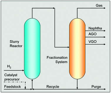 | ||
| Fig. 1 Conceptual scheme of the Eni Slurry Technology (EST) for the upgrading of heavy oils and residues. | ||
EST is based on a concept slightly different from that industrially applied in the past. A catalyst precursor, consisting of an oleo-soluble molybdenum carboxylate (i.e. naphthenate or octoate), is dissolved in the feedstock and the mixture is fed to the reactor, which operates in the temperatures range 673–723 K under a total pressure of ∼15 MPa. H2 is fed through a distributor located at the reactor bottom. Under these conditions, the catalyst precursor is converted to molybdenite, which is crystalline layered MoS2, with an average particle size of a few nanometers (Fig. 2).
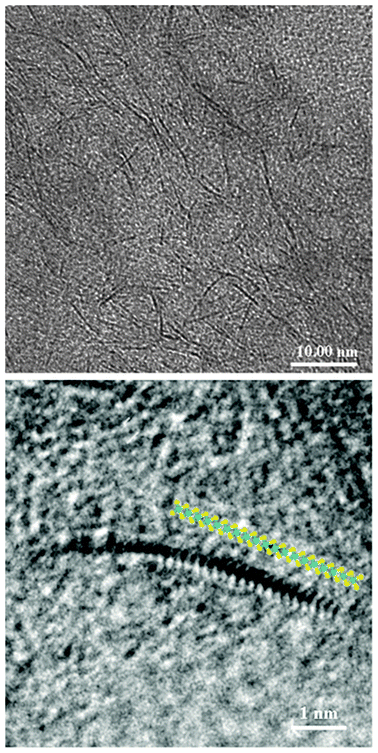 | ||
| Fig. 2 High-resolution transmission electron micrographs (HRTEM) of the THF insoluble fraction of the recycle stream of the EST process, showing the dispersion of the catalyst (top) and a single MoS2 layer with superimposed atomic model (bottom). | ||
After the reactor, the products are separated in a fractionation section constituted of flash units and distillation columns. The residual heavy fraction at the bottom of the vacuum distillation column, which contains all the catalyst, is recycled back to the reactor and only a small part of the heavy fraction is purged (1 to 3 wt% of the fresh feed) to remove the accumulation of coke precursors and of the Ni and V sulfides derived from the organometallic compounds originally present in the feedstock. With the purge, a limited amount of MoS2 is also removed and therefore an equivalent amount of oleo-soluble precursor is continuously fed to the reactor to keep constant its concentration to a few thousand ppm. The purge can be further treated to recover the metals.
The peculiar in situ preparation method adopted in the EST process allows keeping MoS2 dispersed mainly as single layers within the slurry reactor (Fig. 2). The catalyst is rather stable and the catalyst size and shape are maintained constant even for long test runs.
From the start up, the composition of the stream recycled from the bottom of the vacuum distillation column to the reactor changes gradually until it reaches an equilibrium composition (ESI†, Fig. S1). The average molecular weight of the asphaltenes in the recycled stream decreases as a consequence of the cracking and hydrogenation reactions, and smaller molecules containing aromatic rings are formed.
These results were the consequence of a great effort of chemistry and engineering optimization and they supported the decision to build the first full-scale industrial plant. At the same time, we were engaged with research activity aimed to further improve the technology through the amelioration of the catalyst, whose characteristics were deeply investigated. In particular, a possibility would be to couple the molybdenite catalyst with a second cracking catalyst to obtain what we called “dual catalyst system”. In this way, some characteristics such as cracking activity, and nitrogen removal, could be improved even if drawbacks in terms of catalyst lifetime should be managed.
Experimental
Catalytic tests
Two different experimental apparatuses were used to evaluate and compare the performance of different catalytic systems. The first series of experiments was carried out using an ebullated bed reactor plant, which includes a 7.5 L ebullated bed reactor, equipped with a pump that carries out the external recirculation of the liquid phase through a special recovery system and a check valve (ESI†, Fig. S2). The hydrotreating catalyst (1800 g in 1.5 mm pellets) is confined inside the reactor by top and bottom grids and ebullated by the liquid flow.An extruded Ni–Mo supported over alumina catalyst, prepared according to well-known procedures,15 was used in the reference case. The characteristics of the catalyst are reported in the ESI, Table S1.† Average reaction temperature was 430 °C. The feed (Ural Vacuum Residue, see characterization in Table 1) is mixed with hydrogen at 13 MPa pressure and fed to the reactor. Typical fresh feed flow-rate is 800–1000 g h−1.
| Dm@15 °C = density at 15 °C; DAO-C5 = deasphalted oil fraction separated with n-pentane; Sim-dist HT750 = simulated distillation performed following the standard method ASTM D6352. The data reported represent the mass fractions having the boiling points below the temperature indicated in the last column. | |||
|---|---|---|---|
| Dm@15 °C (kg m−3) | 1010.0 | Sim-dist – HT750 | (°C) |
| Viscosity (cSt): | |||
| 60 °C | 2625.7 | 0 wt% | 242.8 |
| 135 °C | 424.8 | 5 wt% | 325.8 |
| 160 °C | 21.8 | 10 wt% | 397.6 |
| Elemental Composition: | 20 wt% | 473.8 | |
| C (wt%) | 86.1 | 30 wt% | 527.8 |
| H (wt%) | 10.7 | 40 wt% | 566.4 |
| S (wt%) | 2.82 | 50 wt% | 597.6 |
| N (ppmw) | 5424 | 60 wt% | 628.0 |
| Fe (ppmw) | 47 | 70 wt% | 662.2 |
| Ni (ppmw) | 61 | 80 wt% | 705.2 |
| V (ppmw) | 142 | 88.9 wt% | 750.0 |
| Mo (ppmw) | 0 | ||
| Asphaltenes-C5 (wt%) | 11.1 | ||
| DAO-C5 (wt%) | 88.9 | ||
The product stream exits from the reactor and enters the separation section, equipped with HP/LP separators and a vacuum distillation column. The main separator operates at a temperature between 320 and 350 °C and it separates the effluent into a gas phase and a heavy liquid.
The latter is sent to the vacuum column, from which a distillate (vacuum gas oil, VGO) from the head and the bottom fraction are obtained. The bottom is recycled, mixed with the fresh feed and fed to the reactor.
The same test was repeated by adding to the feedstock a Mo precursor, transformed in situ in MoS2, in order to obtain a Mo concentration of 2000 ppmw in the reactor.
This experimental set-up, with ebullated bed reactor and extruded solid catalyst is suitable mainly to observe the fate of the metals contained in the feedstock and to evaluate the metal removal efficiency of the catalytic system.
A second series of tests was aimed at defining the performance of the dual catalyst system and to quantify the advantages in terms of conversion, product quality and coke formation. The tests were carried out in a plant equipped with a slurry phase reactor with continuous extraction of the products in the vapor phase. This plant (ESI, Fig. S3†) allows high flexibility in operating condition variation and it also allows periodic extraction of the catalyst from the reactor and fresh catalyst addition during the test run. The reactor is a mechanically stirred 600 cm3 volume autoclave. Liquid feedstock (Ural vacuum residue) and hydrogen are continuously fed to the reactor. Vapor products are extracted from the top of the reactor and condensed at room temperature. The feed flow rate is regulated in order to maintain a constant volume of liquid in the reactor, usually in the range 20–30 g h−1.
The periodic purge of the liquid and fresh catalyst make-up are made through a system of pneumatic valves. Typical operating conditions are 430 °C temperature and 13 MPa pressure. Mo precursor is fed into the reactor at the beginning of the test at about 2000 ppmw concentration. A typical cracking catalyst (microsphere shaped catalyst, containing about 30 wt% of H–Y zeolite and silico–alumina (ESI, Table S2†)) was used. Solid catalyst in dual catalyst tests is added and removed in a batch-wise manner, in order to maintain a 30–40% amount, referred to as the reaction holdup.
Characterization
C, H, and N analyses were performed with a LECO TRUSPEC CHN analyzer following the standard method ASTM D5291; the S content was determined with a LECO TRUSPEC S analyzer following the standard methods ASTM D1552 (high S content) or ISO 20846 (low S content).The dual catalyst system was investigated by scanning electron microscopy (SEM) and transmission electron microscopy (TEM) both coupled with energy dispersive spectroscopy (EDS). SEM micrographs were collected by a field emission SEM JEOL JSM-7600F equipped with an EDS system by Oxford (INCA). The observations are carried out on embedded and polished powder. EDS analyses were collected, also on sectioned samples, by STEM with a TEM Zeiss Libra 120 equipped with a FISCHIONE high-angle annular dark-field detector (HAADF) and an EDS system by Oxford (INCA).
Results and discussion
The main role of molybdenite in hydroprocessing is the production of active hydrogen that limits the formation of coke and promotes the conversion of molecules containing heteroatoms with the formation of H2S, NH3 and Ni and V sulfides. The activity towards cracking is very low; therefore, in the slurry processes, cracking reactions have mainly a thermal origin.The catalytic properties of MoS2 are described in several papers,16,17 but, in spite of the important efforts devoted, the catalytic properties of molybdenite are not completely understood. There are two main models that explain the behavior of this catalyst. The “Rim and Edge” model proposed by Chianelli and Daage18 assumes that in a MoS2 crystal the top and bottom planes are not active, while on the remaining part of the crystals two types of catalytic sites exist, one on the external rim of the upper and lower layers, the other on the lateral edges.
According to this model, the “edge” sites are active in the desulphurization reaction, while the “rim” sites are active in both desulphurization and hydrogenation reactions. The catalytic activity of the sites is determined by the strength of the Mo–S bond.19 According to the other model (Brim model), the active sites are located either on the edge of the MoS2 layers or on the basal plane immediately near to the edge (bright brim sites), in an area characterized by a continuous electronic structure with a metallic conductivity character.20,21
In both cases, the most effective catalyst is constituted of a single layer of molybdenite with an average diameter as small as possible. It appears therefore almost impossible to improve further the characteristics of the actual MoS2 catalyst since, being constituted of single layers with an average particle size of 5–6 nm, it already approaches the ideal figure. So, we tried to improve the system by adding a cracking catalyst. Normally, these catalysts decay rapidly in the presence of such heavy feeds due to the deposition of coke and the neutralization of acid sites by Ni and V ions.22 As molybdenite dispersed in the reaction medium is very effective in activating molecular hydrogen, we decided to verify if this action could protect catalytic cracking from decay.
To test this hypothesis, we planned two series of experiments using equipment designed for this purpose.
In the ebullated bed tests, it is possible to compare the behavior of the solid Ni–Mo extruded catalyst in the reference case, with the catalytic system made of solid catalyst plus dispersed catalyst (dual catalyst system). In the “dual catalyst mode”, the Ni–Mo supported catalyst showed only a limited decay of its activity and a higher conversion compared to the test with Ni–Mo catalyst only (ESI†, Fig. S4). Moreover, in the absence of MoS2, no metals were detected in the recycled stream, indicating that all Ni and V coming from the feed were accumulated on the solid catalyst, while in the presence of dispersed MoS2 the metals were detected and were accumulated in the recycled stream ((ESI†, Fig. S5). This indicates that MoS2 converts Ni and V to the corresponding sulfides before they make contact with the solid catalyst. Dispersed MoS2 particles are much more effective in catalysing the hydrogenation and decomposition of the large organometallic molecules of the feedstock, which can hardly access the pores of the solid catalyst.
This feature prevents the deposition of Ni and V on the solid catalyst. These tests have unequivocally confirmed the ability of MoS2 to protect the solid catalyst from poisoning due to metal accumulation.
The second series of tests in the slurry-phase reactor confirmed the beneficial effects of the dual catalyst system towards coke formation and quantified the advantages in terms of conversion and product quality. Four different tests were done: (a) reference test with hydrogen only and no catalyst; (b) test with cracking catalyst only; (c) test with nano-dispersed MoS2 catalyst only; (d) test with dual catalyst system: both cracking catalyst and MoS2.
The main results are reported in Fig. 3, where the productivity for making distillate products is compared for the four tests. At the very beginning, the highest productivity is obtained with the cracking catalyst. However, the test was stopped after only 6 hours because of the huge amount of coke formed. The reference test (no catalysts) and that with only MoS2 gave the same productivity, in agreement with the properties of molybdenite alone, which is a good hydrogenation catalyst but does not affect the conversion very much. The dual catalyst system allows a higher productivity compared to the reference and to only MoS2 tests over about 20 hour. The combination of the cracking catalyst with the Mo-based hydrogenating catalyst allows us to obtain a stable catalytic system which minimizes coke formation and protects the cracking catalyst from quick deactivation. This effect is clearly demonstrated by the amount of coke collected into the reactor at the end of each run.
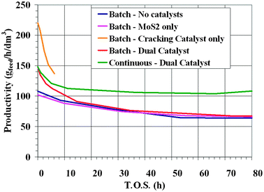 | ||
| Fig. 3 Productivities observed in the different slurry reactor tests. | ||
Table 2 compares the rate of coke formation for the different tests. For the cracking catalyst case the coke formation is almost two orders of magnitude higher than in the other conditions. The relevant information is that coupling the cracking catalyst with MoS2 results in much lower coke formation, very close to what is obtained in the reference and in the MoS2 runs. Starting from the positive results obtained with the dual catalyst system, a test was performed in order to simulate a process where the catalyst is periodically extracted from the reactor together with a fraction of the heavy liquid products. The extracted used solid catalyst, after filtration is washed and regenerated by calcination. A regenerated catalyst addition was made after any extraction to keep constant the catalyst amount in the reactor. An oleo-soluble Mo-precursor, which converts in situ in MoS2, is fed with the feedstock. The liquid fraction extracted from the reactor, after separation from the solid catalyst, is recycled back into the reactor together with the dispersed MoS2. The results obtained with this dual catalyst test with periodic catalyst replacement (Continuous-Dual Cat., green curve in Fig. 3) demonstrate a clear improvement over the performances obtained with MoS2: productivity is more than 50% higher.
Concerning the quality of the products, Fig. 4 shows the desulphurization (HDS, (a)) and de-nitrogenation (HDN (b)) activity for the different runs. It is well known that HDS activity of MoS2 is high, as confirmed by data in Fig. 4a. Dual catalysts runs equal and slightly overcome the HDS activity of molybdenite. However, the dual catalyst system gives relevant improvements in HDN, where molybdenite alone is not so effective. The HDN activity (Fig. 4b) for the dual catalyst is much higher than that of MoS2 and of the reference test. The improvements are even more evident in the test with continuous catalyst replacement, where the HDN is always above 90%. This very high activity in sulfur and nitrogen removal will have a strong positive impact on the downstream product upgrading operations. This is another important breakthrough of this new catalytic system, since the diesel fuel obtained can be brought to market specification with only a mild finishing treatment.
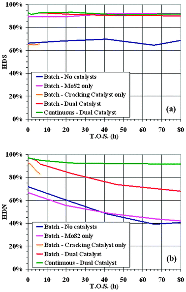 | ||
| Fig. 4 Hydrodesulfurization (HDS, a) and hydrodenitrogenation (HDN, b) activity in slurry reactor tests. | ||
After the dual catalyst test, the catalyst microspheres were separated by filtration and dried before being observed by electron microscopy. SEM/EDS analysis showed that Mo and S are mainly located on the external surface of the microspheres of the cracking catalyst, while they are practically absent in the bulk (Fig. 5). A more detailed investigation made by TEM showed that MoS2 is preferentially located in the coke deposits formed on the external layer of the particles (Fig. 6), in the form of isolated layers homogeneously distributed on top of the coke deposit (ESI†, Fig. S6). The affinity of MoS2 for aromatic carbon has been reported in the literature. A natural C–MoS2 mixed-layer phase with similarities to molybdenite occurring in metalliferous black shales from Southern China, has been reported in the literature.23
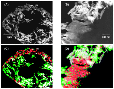 | ||
| Fig. 5 TEM micrographs showing the internal part of a cracking catalyst particle (A), a detail of the external layer (B) and the corresponding images with superimposed EDS maps of the distribution of Si (green), Al (white) and Mo + S (red) (C and D). The micrograph and the maps collected at higher magnifications show that MoS2 is preferentially located in correspondence with the accumulations of coke (see (B) and (D)). | ||
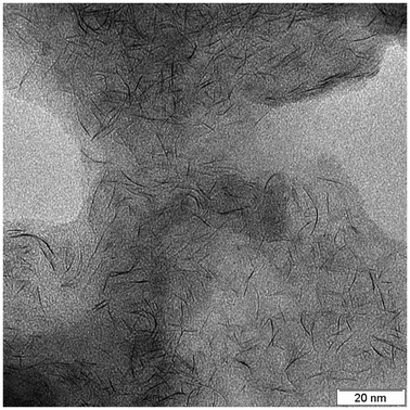 | ||
| Fig. 6 TEM micrograph showing the dispersion of the layers of MoS2 in the coke present on the external surface of the cracking catalyst. | ||
Conclusions
The new catalytic system allows for the first time the use of cracking catalysts for the total conversion of heavy and extra-heavy oils to middle distillates. The nano-dispersed MoS2 has been proven to be effective in protecting the cracking catalyst, under the selected process conditions, from metals and coke deposition. The hypothesis that explain the observed behaviour is reported in Fig. 7. The large number of MoS2 particles per unit volume, which are present mainly as a single layer, are probably responsible for the very high HDM activity and the rapid conversion of the organometallic compounds present in the feedstock to the corresponding metal sulfides.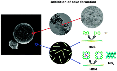 | ||
| Fig. 7 Hypothesis which explains how nano-dispersed MoS2 can protect the cracking catalyst from coke and metal deposition. | ||
This is the most probable reason for the protection of the cracking catalyst from metal deposition while the affinity of MoS2 for the aromatic carbon is probably the origin of the capability to protect the cracking catalyst from coke deposition. As shown before, the particles of MoS2 have the tendency to adhere to the coke spots at the surface of the cracking catalyst and from there promote the formation of active hydrogen which slows down the rate of coke deposition.
The application of these results to the hydrocracking slurry technology will make the utilization of unconventional oil more effective for the production of good quality distillates and this achievement will secure us more time and resources to complete the development of a totally renewable energy supply system.
Notes and references
- Word Energy Outlook 2011, IEA, International Energy Agency, p. 71.
- M. S. Rana, V. Samano, J. Ancheyta and J. A. I. Diaz, Fuel, 2007, 86, 1216 CrossRef CAS.
- M. Marafi and A. Stanislaus, Appl. Catal., A, 1997, 159, 259 CrossRef CAS.
- S. Kressmann, F. Morel, V. Harlé and S. J. Kasztelan, Catal. Today, 1998, 43, 203 CrossRef CAS; J. F. Mosby, G. B. Hoekstra, T. A. Kleinhentz and J. M. Sroka, Hydrocarbon Process. (1966–2001), 1973, 5, 93 Search PubMed.
- C. H. Barkelew and B. S. Gambhir, ACS Symp. Ser., 1984, 237, 62 Search PubMed.
- B. Scheffer, M. A. van Koten, K. V. Robschlager and F. C. de Boks, Catal. Today, 1998, 43, 217 CrossRef CAS.
- M. R. Gray, Upgrading petroleum residues and heavy oils, Marcel Dekker Inc., New York, 1994 Search PubMed.
- F. Morel, S. Kressmann, V. Harlé and S. Kasztelan, Stud. Surf. Sci. Catal., 1997, 106, 1 CrossRef CAS.
- Friedrich Bergius Nobel Laureate Lecture, http://nobelprize.org/nobel_prizes/chemistry/laureates/1931/bergius-lecture,pdf.
- M. Pier, Zeit. Elektochem. Phys. Chem., 1949, 53, 291 CAS.
- G. Fauser, La Chimica e l’Industria, 1937, XIX(3), 113 Search PubMed.
- R. R. Chianelli, M. H. Siadati, M. Perze De la Rosa, G. Berhault, J. P. Wilcoxon, R. Bearden Jr. and B. L. Abrams, Catal. Rev., 2006, 48, 1 CAS.
- N. Panariti, A. Delbianco, G. Del Piero and M. Marchionna, Appl. Catal., A, 2000, 204, 203 CrossRef CAS.
- G. Rispoli, D. Sanfilippo and A. Amoroso, Hydrocarbon Process., 2009, 12, 39 Search PubMed.
- J. Grimblot, Catal. Today, 1998, 41, 111 CrossRef CAS.
- N. Panariti, A. Delbianco, G. Del Piero, M. Marchionna and P. Carniti, Appl. Catal., A, 2000, 204, 215 CrossRef CAS.
- S. Wang, C. An and J. Yuan, Materials, 2010, 3, 401 CrossRef CAS.
- M. Daage and R. R. Chianelli, J. Catal., 1994, 149, 414 CrossRef CAS.
- R. R. Chianelli, G. Berhault, P. Raybaud, S. Kasztelan, J. Hafner and H. Toulhoat, Appl. Catal., A, 2002, 227, 83 CrossRef CAS.
- S. Helveg, J. V. Lauritsen, E. Laegsgaard, I. Stensgaard, J. K. Norskov, B. S. Clausen, H. Topsøe and F. Besenbacher, Phys. Rev. Lett., 2000, 84, 951 CrossRef CAS.
- F. Besenbacher, M. Brorson, B. S. Clausen, S. Helveg, B. Hinnemann, J. Kibsgaard, J. V. Lauritsen, P. G. Moses, J. K. Norskov and H. Topsøe, Catal. Today, 2008, 130, 86 CrossRef CAS.
- R. Galiasso Tailleur, Fuel Process. Technol., 2007, 88, 779 CrossRef.
- L.-S. Kao, D. R. Peacor, R. M. Coveney Jr., G. Zhao, K. E. Dungey, M. D. Curtis and J. E. Penner-Hahn, Am. Mineral., 2001, 86, 852 CAS.
Footnote |
| † Electronic supplementary information (ESI) available: Evolution of the average molecular weight and characteristics of asphaltenes during a long test run; schemes of the pilot plants and characteristics of the catalysts, results of the catalytic tests. See DOI: 10.1039/c2cy20448g |
| This journal is © The Royal Society of Chemistry 2013 |
