Spontaneous electric fields in films of CF3Cl, CF2Cl2 and CFCl3
Andrew
Cassidy
a,
Oksana
Plekan
a,
Richard
Balog
a,
Nykola C.
Jones
b and
David
Field
*a
aDepartment of Physics and Astronomy, Aarhus University, DK-8000 Aarhus C, Denmark. E-mail: dfield@phys.au.dk
bInstitute for Storage Ring Facilities (ISA) and Department of Physics and Astronomy, Aarhus University, DK-8000 Aarhus C, Denmark
First published on 24th October 2012
Abstract
Data are presented showing the spontaneous formation of electric fields within solid films of the chlorofluorocarbons (CFCs) CF3Cl, CF2Cl2 and CFCl3 as a function of film deposition temperature from 40 K and above. Electric fields, which arise through dipole alignment and lie in the range of a few times 107 V m−1 to a few times 106 V m−1, decrease as the degree of chlorination increases. Maximum deposition temperatures for display of an electric field lie at ∼50 K, ∼65 K and ∼52 K for CF3Cl, CF2Cl2 and CFCl3 respectively. CFCl3 films possess electric fields which show an onset of temporal metastability between deposition temperatures of 46 K and 50 K. CF3Cl and CF2Cl2 demonstrate temperatures of ∼65 K and ∼80 K at which the electric field in the film is removed by heating, so-called Curie points, with decay of the field spread over more than 10 K. CFCl3 displays a comparatively sharp Curie point at 55 K. This variety of behaviour arises despite the resemblance of these three species in terms of electronic structure and gas phase dipole moment, emphasising the requirement for detailed chemical models of this phenomenon.
1 Introduction
The recent detection of spontaneous electric fields in numerous solid films prepared by vapour deposition raises some fundamental questions about the nature of disordered materials.1–4 These newly discovered ‘spontelectric’ solids may be characterised as approximately glassy in structure but with a residual order which gives rise to the observed spontaneous polarisation and electric fields. Investigations into spontelectrics allow a very sensitive probe of the nature of the glassy state and present a challenge to theory which has yet to be met. Note that the nature of spontelectric films is quite distinct from that of glassy ferroelectric structures,5 containing non-interacting islands of order, so-called ‘ferrons’.6 There is no evidence for such ferron structures in spontelectrics.Dipole–dipole interactions and the interaction between the dipole and the spontaneous electric field within the solid have been shown to be intrinsic to the formation of the spontelectric state in solid films.4 This is in contrast to all other solids which show spontaneous polarisation in which polarisation is an extrinsic consequence of the dipolar nature of the constituent molecules, that is, the structure which gives rise to polarisation is due very largely to other forces than dipole–dipole.4,7,8 The purpose of the current paper is to consider the following fundamental question regarding spontelectrics: is the influence of the detailed chemical structure of the constituent species seminal to the nature of their spontelectric behaviour rather than purely their dipole moments? To probe this question, we present data on spontelectric behaviour in the CFCs CF3Cl, CF2Cl2 and CFCl3. These species were chosen since they have similar gas phase dipole moments of 0.500 D, 0.510 D and 0.450 D respectively. They also possess a similar electronic structure exemplified by the similarity of their absorption spectra.9
Each of the three freons investigated here can form orthorhombic crystalline structures when condensed in liquid nitrogen from high pressure and cooled to liquid helium temperatures or condensed directly from the liquid form.10,11 It has been suggested that CF2Cl2 in the crystalline state may display ferroelectric alignment of dipoles11 although no ferroelectric properties have been reported. Crystalline alignment of CF2Cl2 has been reported up to 110 K, significantly greater than the temperature of 80 K at which spontelectric properties are quenched for CF2Cl2. We assume that the CFCs laid down from low pressure, as here, form essentially amorphous layers.
In passing we note that the activity of these three CFCs in the destruction of ozone in the atmosphere of the Earth involves ices formed at typically 210–230 K, that is, very much higher temperatures than are relevant in the present work. Ices in polar stratographic clouds are therefore not expected to have any spontelectric character, since they are formed greatly above any temperature for the spontelectric effect to be found (see Section 2.2) and are anyway composed of a very dilute mixture of CFCs.
In Section 2 we briefly outline the experimental method and present our results, showing the magnitude of the spontelectric effects associated with the chosen CFCs and the upper limits of temperature for which they can be observed. In Section 3 we analyze these results using a model first described in ref. 1. In short we find that CF2Cl2 and CF3Cl show some similarity in spontelectric properties whereas CFCl3 shows distinctly different properties, for example exhibiting temporal decay of the spontelectric state when laid down at 50 K and above.
2 Experimental method and results
2.1 Method
The spontelectric nature of a solid film is established by the presence of a spontaneously generated potential on the surface of the film, at the interface with a vacuum, relative to the substrate on which the film is laid down. The potential of the film surface is measured using a low energy electron beam with high energy resolution, set here to be ∼1.5 meV. The experimental system involves electrons generated through photoionization of Ar at a few mV above the photoionization threshold of 785.6 Å, using monochromatized radiation from the ASTRID synchrotron storage ring at Aarhus. Further experimental details of the synchrotron photoionization source may be found in ref. 1–4 and 12. The voltage applied to the substrate required to null the electron current gives the value of the potential on the surface of the film relative to the potential of formation of the electrons. The latter is nominally zero. The potential of the clean gold substrate relative to the nominal zero of the photoionization region is also recorded and is typically ∼200 mV. The potential on the film surface relative to the gold substrate may be measured with an accuracy of 2–3 mV. The current in the electron beam is set sufficiently low at <700 fA cm−2 (100–200 fA measured) such that the surface potential is not significantly affected by the measurement. This is checked by repeated measurements of the surface potential.Films are prepared under UHV conditions, with a system base pressure of ∼10−10 mbar, and are laid down on a polycrystalline Au substrate, grain size <100 nm, in the form of a 750 nm thick layer of material on Ta. In connection with this, we note that spontelectric potentials have been measured to be independent of the surface on which the active species is deposited.1 The substrate is cooled using a He cryo-cooler to temperatures in the range of 38 K upwards and cleaned by heating to 700 K. Dosing is performed from the background gas, allowing the deposition of uniform films. Temperature programmed desorption (TPD) is used to estimate the number of monolayers (ML) deposited. All materials are chemically stable on the amorphous gold surface at the temperatures employed. Mass spectral data associated with TPD show no evidence of any decomposition of parent species. The measured desorption temperature for CF3Cl is 99 K, for CF2Cl2 is 117 K and for CFCl3 is 130 K. Dosing rates were 7 ML min−1 for CF3Cl, 2 ML min−1 for CF2Cl2 and 5 ML min−1 for CFCl3. Exceptionally the dosing rate for thin layers of CF3Cl at 50 K was 3 ML min−1 (see Section 2.2.1). Note that absolute numbers of ML are known to be better than ±20–30%. Relative values are however accurate at the few % level.
2.2 Results
The potential formed on the surface of a film at a specific temperature of deposition is measured as a function of the number of monolayers deposited. This yields the electric field in the film, Eobs, as a function of deposition temperature, in terms of V m−1, given the film thickness. All electric fields in the present work are measured to be negative, in common for example with isopentane but in contrast to N2O.1 In this connection the presence of a positive or negative spontelectric potential is associated with the binding by physisorption of spontelectric species to the surface and thus with the initial breaking of the symmetry in the system. The nature of the binding is chemically specific and thus requires detailed modelling to predict, an aspect presently lacking.As in earlier work we introduced the direction cosine, 〈μz〉/μ, termed the degree of dipole alignment. Here 〈μz〉 is the space averaged component, or the time averaged component for any point, of the dipole normal to the film, that is, in the z-direction and μ is the value of the full dipole of the molecule in the solid state. Values of the degree of dipole alignment are estimated using 〈μz〉/μ = ε0EobsΩ/μ, where Ω is the effective volume of the molecule.1 The value of μ is given by μ = μ0/(1 + αk/s3) where α is the molecular polarizability of the relevant freon, s is the average spacing between successive layers (see Section 3), k = 11.034 and μ0 is the gas phase dipole moment of the relevant species.13,14 Note that the z-direction is measured normal to and away from the gold surface. Thus the dipole moment should strictly be expressed as a negative quantity since in the species considered here the negative end of the dipole tends to point in the positive z-direction. The observed field is negative, μ is negative and hence 〈μz〉/μ, the degree of dipole alignment, derived from 〈μz〉/μ = ε0EobsΩ/μ, is a positive quantity.
All potentials shown in the succeeding figures are relative to the polycrystalline gold substrate. As is well-known,15 small surface potentials arise on deposition of a single ML on clean substrates and these are seen here to be weakly dependent on temperature. Thus for CF2Cl2 for example, extrapolation of data to zero film thickness shows an intercept at −0.34 V for deposition at 45 K and −0.24 V at 65 K.
Data for CF3Cl, CF2Cl2 and CFCl3 are summarized in Table 1 which shows the raw data in terms of mV ML−1 for different temperatures of film deposition. Table 1 also shows derived electric fields, Eobs, and the corresponding degree of dipole alignment. The issue of temporal instability of the spontelectric effect for CFCl3 is considered in Section 2.2.3.
| Temperature/K | mV ML−1 | Electric field/V m−1 | Degree of dipole alignment (〈μz〉/μ) |
|---|---|---|---|
| CF3Cl | |||
| 40 | −11.6 | −4.25 × 10⁷ | 0.075 |
| 45 | −9.02 | −3.28 × 10⁷ | 0.058 |
| 47.5 | −5.39 | −1.97 × 10⁷ | 0.035 |
| 50 | −2.06 | −7.55 × 10⁶ | 0.013 |
| CF2Cl2 | |||
| 45 | −3.97 | −1.43 × 10⁷ | 0.042 |
| 55 | −2.77 | −9.98 × 10⁶ | 0.029 |
| 60 | −1.53 | −5.51 × 10⁶ | 0.016 |
| 65 | −1.13 | −4.07 × 10⁶ | 0.012 |
| CFCl3 | |||
| 43 | −1.33 | −5.32 × 10⁶ | 0.031 |
| 46 | −0.84 | −3.36 × 10⁶ | 0.019 |
| 50 | −0.46 | −1.86 × 10⁶ | 0.011 |
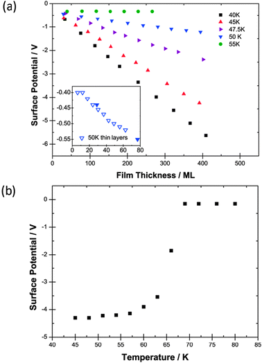 | ||
| Fig. 1 (a) Surface potentials measured for films of CF3Cl as a function of thickness in monolayers (ML) laid down at five different deposition temperatures. 55 K data are included to show the absence of the spontelectric effect. The inset shows data at 50 K for a lower rate of deposition (see text). (b) The variation of the surface potential of a 400 ML film of CF3Cl laid down at 45 K and heated to 80 K showing a Curie point. Errors in experimental values of surface potential are 2–3 mV and of the temperature are ±1 K. | ||
Experiments were also performed to determine if there was a dependence of spontelectric behaviour on the rate of deposition of CF3Cl on timescales of minutes. The inset to Fig. 1a shows data obtained using a rate of deposition of 3 ML min−1, as compared with 7 ML min−1 for data in the main panel, and depositing for a shorter time. The slope of the measured surface potential vs. film thickness remained unchanged within experimental error and thus the spontaneous electric field is unchanged.
Changes in the spontelectric potential in response to heating of a 400 ML layer of CF3Cl, deposited at 45 K are shown in Fig. 1b. The film was heated in 6 K steps, held at the new temperature, the surface potential measured and then heated again and so on. Fig. 1b shows a “Curie point”1 and also illustrates that once established the spontelectric structure is difficult to dislodge. All three species studied show the removal of the spontelectric effect on heating the sample once a certain temperature is reached. There appears therefore to be a temperature-induced transition between the spontelectric and the disordered state, providing further evidence that this order–disorder transition is characteristic of spontelectrics.1 As noted in ref. 1, the dipole-aligned structure shows rigidity and remains intact despite substantial electromechanical stress. This behaviour is accentuated for CF3Cl since the material remains dipole aligned at temperatures more than 10 K higher than the deposition temperatures in the experiments illustrated in Fig. 1a, at any rate on the timescale of hours of the experiments. Similar results are found for CF2Cl2 (see Section 2.2.2).
We note that the residual surface potential is different above the Curie point compared with the values quoted for low temperature with extrapolation to zero coverage. The same observation applies to CF2Cl2 and numerous other spontelectric materials which show Curie points.
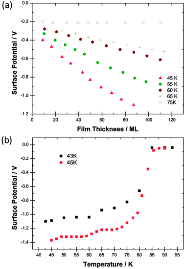 | ||
| Fig. 2 (a) Surface potentials measured for films of CF2Cl2 as a function of thickness in monolayers (ML) laid down at five different deposition temperatures. 75 K data are included to show the absence of the spontelectric effect. (b) Black points (upper curve): the variation of the surface potential of a 90 ML film of CF2Cl2 laid down at 43 K and heated to 95 K showing a Curie point. Red points (lower curve): the variation of the surface potential of a 120 ML film of CF2Cl2 laid down at 45 K and heated to 95 K. | ||
Fig. 2b demonstrates a Curie point with a similar slow inception to that of CF3Cl but with a value ∼15 K higher. The lower curve however shows clear structure at around 60 K to 65 K in an experiment conducted with 2 K steps and verifies that the structure seen in the black points, with 5 K steps, is genuine. It would appear that solid CF2Cl2 may form two spontelectric configurations which transform one into the other at >60 K. Alternatively there may be two co-existent configurations with the conversion of one into the other at >60 K.
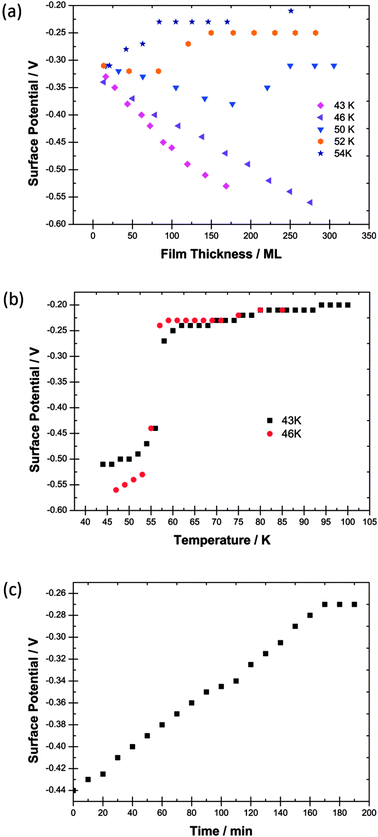 | ||
| Fig. 3 (a) Surface potentials measured for films of CFCl3 as a function of thickness in monolayers (ML) laid down at five different deposition temperatures. (b) The variation with temperature of the surface potential of 120 ML and 250 ML films of CFCl3 laid down at 43 K and at 46 K respectively. (c) The temporal decay of the surface potential of a film of CFCl3 deposited at 50 K. | ||
Data in Fig. 3a and b differ considerably from those for CF3Cl and CF2Cl2 in Fig. 1a, b and 2a, b respectively. The electric fields in the CFCl3 films are considerably weaker than in the two other species. For example at 45 K for CF3Cl and CF2Cl2 and 46 K for CFCl3, fields are, respectively, 3.28 × 10⁷ V m−1, 1.32 × 10⁷ V m−1 and 3.36 × 10⁶ V m−1. For any temperature, the degrees of dipole alignment also tend to be lower for CFCl3 than for the other two species; see Table 1 and Section 3.
There is strong temporal dependence of the spontelectric effect on films laid down at 50 K and above for CFCl3. This is illustrated in Fig. 3c which shows the temporal decay of the surface potential on a CFCl3 film deposited at 50 K. The spontelectric effect disappears after 3 hours. The onset of temporal instability with temperature of film deposition is quite abrupt. No such effect of spontelectric decay is seen for films of CFCl3 deposited at 46 K.
This abrupt onset of instability is reflected by the Curie behaviour shown in Fig. 3b. In contrast to Curie experiments for CF3Cl and CF2Cl2 shown in Fig. 1b and 2b, the Curie point for CFCl3 occurs over a range of 1 to 2 K, even more rapidly than the value of ∼5 K recorded for isoprene.1 Moreover the Curie effect occurs at a temperature of 55–56 K in accord with the maximum value of deposition temperature for which a spontelectric effect can be observed: see Fig. 3a. This behaviour is in contrast to CF3Cl and CF2Cl2.
3 Analysis
A mean-field model, originally introduced in ref. 1 and also employed successfully in ref. 4, is used here to analyse the results shown in Fig. 1a, 2a and 3a for the temperature dependence of the electric field and the degree of dipole orientation in the CFC films. As mentioned in the introduction, the dipolar nature of the constituent molecules is intrinsic to spontelectric behaviour, one feature which sets spontelectrics apart from ferroelectrics.4 Dipole–dipole interactions play a central role, with an infinite range order spontaneously generated through an interplay between dipole alignment, the electric field and the thermal motion associated with the temperature at which the solid is deposited.The model is based on the concept that the z-component of the local electric field, Ez, is composed of two parts. The first is the local field at any molecular site as described in standard texts.16–18 In a randomly oriented collection of species, that is, an amorphous solid, this part of the local field averages spatially or in time to zero and is therefore overall macroscopically symmetrical. The assumption is made that this holds true for the present materials. This symmetrical part is expressed as a constant term, Esym, plus a dipole–dipole term, parameterized through Esymζ(〈μz〉/μ)2 reflecting the fact that all such interactions, dipole-image charge, extended dipoles and arrays of dipoles, follow this squared relation.19–21 Physically the dipole–dipole term represents the tendency to hinder relative intermolecular rotational motion.
The second part of the local field is equivalent to the depolarization field in materials depolarized by an external field.22 In spontelectrics however this field is internal and spontaneous. This contribution is proportional to the degree of dipole alignment and is parameterized through 〈Easym〉〈μz〉/μ. Since there is no applied field in our experiments, this second part represents the full field which permeates the system and is the field estimated from our experiments. This term acts locally in opposition to the symmetrical part and represents the infinite range field created by the average dipoles and experienced by an average dipole. The ζ(〈μz〉/μ)2 term in the symmetrical part of the local field introduces feedback between the depolarization field and the local field. This feedback is essential to describe the variation of the degree of dipole alignment with temperature.
Hence, using atomic units throughout,
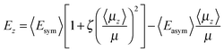 | (1) |
Mean field theory gives an implicit expression for 〈μz〉/μ yielding the familiar Langevin function for orientational interactions16
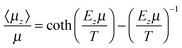 | (2) |
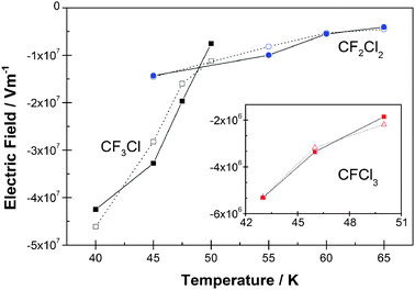 | ||
| Fig. 4 The variation of the electric field, Eobs, as a function of deposition temperature for CF3Cl, CF2Cl2 and CFCl3, using values in Table 1, compared with fits obtained using eqn (1) and (2). Fits are shown as open symbols and experimental values as solid symbols. Fitting parameters 〈Esym〉, 〈Easym〉 and ζ are given in Table 2. | ||
| CF3Cl | CF2Cl2 | CFCl3 | |
|---|---|---|---|
| μ o (D) | 0.500 | 0.510 | 0.45 |
| α (Å3) | 4.740 | 6.370 | 7.913 |
| Ω (Å3) | 121.36 | 130.78 | 140.6 |
| S (nm) | 0.31 | 0.28 | 0.25 |
| μ (D) | 0.181 | 0.119 | 0.025 |
| 〈Esym〉 (V m−1) | −6.96 × 10⁷ | −7.00 × 10⁷ | −1.05 × 10⁸ |
| 〈Easym〉 (V m−1) | −5.63 × 10⁸ | −2.88 × 10⁸ | −1.73 × 10⁸ |
| ζ | 500 | 900 | 1550 |
4 Discussion and conclusions
It is evident from Fig. 4 that the three CFCs possess spontelectric fields which lie in the order CF3Cl > CF2Cl2 > CFCl3. One important factor in this difference in spontelectric behaviour would appear to be the depolarization of the molecules in the solid phase. Increased chlorination leads to an increased polarizability (see Table 2) and therefore increased depolarization in CFCl3, yielding a smaller dipole moment in the solid. By contrast, individual symmetrical terms in Eqn (1) and (2) yield fields in the reverse order to the spontelectric field, that is, CF3Cl < CF2Cl2 < CFCl3. For example the ‘locking’ field which hinders rotation, 〈Esym〉 ζ(〈μz〉/μ)2 is −5.6 × 10⁷ V m−1, −1.1 × 10⁸ V m−1 and −1.6 × 10⁸ V m−1 for CF3Cl, CF2Cl2 and CFCl3, respectively, at 45 K (or 46 K for CFCl3) using values in Tables 1 and 2. Evidently an interplay between the symmetric and asymmetric terms leads to the observed behaviour through the feedback inherent in Eqn (1) and (2).The abrupt onset of temporal instability with deposition temperature of the spontelectric nature of CFCl3 (Fig. 3a) arises from the fragility of the spontelectric system. This is associated with a weak spontelectric field coupled with a weak solid state dipole. The temporal change from spontelectric structure to non-spontelectric, as seen in Fig. 3c for CFCl3, arises through a relocation of the dipoles to form a random distribution. The relative values of asymmetric and symmetric terms in Ez (Eqn (1)) may be taken as a measure of this relocation to be energetically favourable. Inserting values of 〈Esym〉, 〈Easym〉, ζ and 〈μz〉/μ from Tables 1 and 2 and considering only the highest temperatures of deposition, the ratio of asymmetric to symmetric terms for CFCl3 is 0.017 at 50 K (and 0.02 at 46 K), for CF2Cl2 is 0.066 at 65 K and for CF3Cl is 0.14 at 50 K. This suggests an onset of collapse of the spontelectric structure when the asymmetric term in Eqn (1) becomes <2% of the symmetric. In summary it is evident that for CFCl3 a combination of sensitivity to motional fluctuations and the weakness of the asymmetric field, that is the measured field, itself a reflection of the low values of 〈μz〉/μ, is the root cause of the different behaviour encountered in this species compared to CF3Cl or CF2Cl2.
In connection with the metastability of CFCl3 illustrated in Fig. 3a, none of the three species discussed here enters the regime in which the degree of dipole alignment increases with temperature of deposition, as observed in methyl formate,4 noting that such a phenomenon may be accompanied by metastability of the spontelectric effect. The regime of a positive value of d〈μz〉/μ/dT occurs at a critical degree of dipole alignment4 given approximately by 〈Easym〉/2ζ〈Esym〉, that is, 0.008 for CF3Cl, 0.0023 for CF2Cl2 and 0.0006 for CFCl3. The lowest measured values are 0.02 for CF3Cl at 50 K, 0.012 for CF2Cl2 at 65 K and 0.013 for CFCl3 at 50 K. The inference is that collapse of the spontelectric structure intervenes precluding achievement of the critical degree of dipole alignment associated with a change in sign of d〈μz〉/μ/dT.
We conclude that the spontelectric characteristics of the three apparently closely related CFCs depend critically on chemical forces which are not reflected in the similar gas phase dipole moments of the individual molecules. In order to model spontelectric effects it would therefore appear essential to perform sophisticated calculations of solid state structures including an accurate description of medium to long range forces special to any system. For the present, experimental data remain the only means to establish the existence of a range of conditions for which spontelectric behaviour is found. The present results reinforce the view set out in earlier work1–4 that structure and dipole alignment in spontelectric materials are intrinsically dictated by dipole–dipole interactions. If these are modified, for example by increasing temperature, then the structure changes accordingly.
Notes and references
- O. Plekan, A. Cassidy, R. Balog, N. C. Jones and D. Field, Phys. Chem. Chem. Phys., 2011, 13, 21035–21044 RSC.
- R. Balog, P. Cicman, N. C. Jones and D. Field, Phys. Rev. Lett., 2009, 102, 073003 CrossRef.
- D. Field, O. Plekan, A. Cassidy, R. Balog and N. C. Jones, Europhys. News, 2011, 42, 32 CrossRef CAS.
- O. Plekan, A. Cassidy, R. Balog, N. C. Jones and D. Field, Phys. Chem. Chem. Phys., 2012, 14, 9972 RSC.
- M. E. Lines, Phys. Rev. B: Solid State, 1977, 15, 388 CrossRef CAS.
- Y. Xu and J. D. MacKenzie, J. Non-Cryst. Solids, 1999, 246, 136 CrossRef CAS.
- S. Horuchi and Y. Tokura, Nat. Mater., 2008, 7, 357 CrossRef.
- Y. Okayabshi, E. Ito, T. Isoshima and M. Hara, Appl. Phys. Express, 2012, 5, 055601 CrossRef.
- See the Max Planck Institute Mainz-UV-VIS Atlas of Gaseous Molecules: H. K. Rudek and G. K. Moortgat, MPI für Chemie, Atmospheric Chemistry Division, Mainz, Germany, 2012 Search PubMed.
- G. S. Pawley and A. W. Hewat, Acta Crystallogr., Sect. B: Struct. Crystallogr. Cryst. Chem., 1985, 41, 136 CrossRef.
- J. K. Cockcroft and A. N. Fitch, Z. Kristallogr., 1991, 197, 121 CrossRef CAS.
- S. V. Hoffmann, S. L. Lunt, N. C. Jones, D. Field and J.-P. Ziesel, Rev. Sci. Instrum., 2002, 73, 4157 CrossRef CAS.
- A. Natan, L. Kronik, H. Haick and R. T. Tung, Adv. Mater., 2007, 19, 4103 CrossRef CAS.
- J. Topping, Proc. R. Soc. London, Ser. A, 1927, 114, 67 CrossRef.
- G. McElhinney and J. Pritchard, Surf. Sci., 1976, 60, 397 CrossRef.
- C. Kittel, Introduction to Solid State Physics, John Wiley and Sons Inc., 3rd edn, 1968 Search PubMed.
- J. C. Burfoot, Ferroelectrics, van Nostrand Co. Ltd., 1967 Search PubMed.
- in Physics of Ferroelectrics, A Modern Perspective, Section 2.2. Topics in Applied Physics, ed. K. M. Rabe, C. H. Ahn and J.-M. Triscone, Springer Berlin Heidelberg New York, 2007 Search PubMed.
- E. Cohen de Lara and J. Vincent-Geisse, J. Phys. Chem., 1976, 80, 1922 CrossRef CAS.
- B. L. Maschhoff and J. P. Cowin, J. Chem. Phys., 1994, 101, 8138 CrossRef CAS.
- D. Fernandez-Torre, O. Kupiainen, P. Pyykkö and L. Halonen, Chem. Phys. Lett., 2009, 471, 239 CrossRef CAS.
- H. Kliem, M. Kuehn and B. Martin, Ferroelectrics, 2010, 400, 41 CrossRef CAS.
| This journal is © the Owner Societies 2013 |