Exploring a charge-central strategy in the solution of Poisson's equation for biomolecular applications
Received 6th June 2012, Accepted 24th October 2012
First published on 24th October 2012
Abstract
Continuum solvent treatments based on the Poisson–Boltzmann equation have been widely accepted for energetic analysis of biomolecular systems. In these approaches, the molecular solute is treated as a low dielectric region and the solvent is treated as a high dielectric continuum. The existence of a sharp dielectric jump at the solute–solvent interface poses a challenge to model the solvation energetics accurately with such a simple mathematical model. In this study, we explored and evaluated a strategy based on the “induced surface charge” to eliminate the dielectric jump within the finite-difference discretization scheme. In addition to the use of the induced surface charges in solving the equation, the second-order accurate immersed interface method is also incorporated to discretize the equation. The resultant linear system is solved with the GMRES algorithm to explicitly impose the flux conservation condition across the solvent–solute interface. The new strategy was evaluated on both analytical and realistic biomolecular systems. The numerical tests demonstrate the feasibility of utilizing induced surface charge in the finite-difference solution of the Poisson–Boltzmann equation. The analysis data further show that the strategy is consistent with theory and the classical finite-difference method on the tested systems. Limitations of the current implementations and further improvements are also analyzed and discussed to fully bring out its potential of achieving higher numerical accuracy.
Introduction
Electrostatic interactions play significant roles in the structural, functional, and dynamic properties of biomolecules. Efficient and accurate modeling of electrostatic interactions has been an active research topic in computational studies of biomolecules.1–26 In modeling electrostatic interactions, the solvation effect has to be taken into consideration. Both explicit/atomistic representation and implicit/continuum representation of solvent molecules are possible and have received wide acceptance in biomolecular simulations. For implicit or continuum solvent treatments, the Poisson–Boltzmann equation (PBE) can be utilized to model the electrostatic interactions of solvation.1–26 In this model, the solute molecule is treated as a region with a low dielectric constant and the solvent is treated as a region with a high dielectric constant. A number of fixed interior point charges are located at atomic centers. Given the mathematical setup, the PBE can be solved to compute the electrostatic potential distribution and solvation free energy.Apparently the challenge is how to solve the PBE, a three-dimensional partial differential equation, with acceptable efficiency without losing too much accuracy given limited memory and speed of current computing resources. The computational difficulty lies in the extremely high dimensionality of a typical biomolecular system, ranging from thousands to millions of atoms in typical biomolecular studies. The second difficulty lies in the extremely complex interface geometry between the continuum solvent and a molecular solute that must be properly modeled for accurate solvation interactions.
As there are only a few cases with simple solute geometries where analytical solutions are available, most developmental efforts have been focused on improving efficiency and accuracy of its numerical solutions. Many packages, such as DelPhi,27–29 UHBD,30,31 APBS,32,33 and related modules of Amber34,35 and CHARMM,28,36 are based on the finite-difference methods (FDM)27–34,36–38 to solve the PBE. With FDM, the PBE can be converted into a linear system of finite difference equations with a symmetric positive definite coefficient matrix and can be solved by efficient solvers such as preconditioned conjugate gradient methods.30,34,39–42 However, if a direct discretization is used without taking into account the discontinuity in the dielectric constant, the numerical solutions tend to have large errors, particularly near the solute–solvent interface. To achieve higher order accuracy, for example, second-order accuracy, interface conditions can be enforced as in the immersed interface methods43,44 and the matched interface and boundary methods.45–48 Nevertheless, the coefficient matrix developed in this way may not be symmetric anymore and the preconditioned conjugate gradient method cannot be applied directly.
Boundary element methods (BEM)49–64 focus on the solvent/solute interface to construct a linear system. The unknowns in the system are either the induced surface charges49–52,56,57,59,60 or the normal components of the electric displacement53–55,58,61,62 on the interface. Thus the number of unknowns in the BEM is one order lower than that of the entire domain. However, an extra step of triangulization of the interface is required for the BEM. Furthermore, its efficiency is limited as the integration operator on the interface is most time consuming.
The finite-element method (FEM)65–73 is based on a weak formulation. The electrostatic potential to be solved is approximated by a superposition of a set of basis functions. A linear or nonlinear system of equations for the coefficients produced by the weak formulation has to be solved. A nice property of the FEM is that the mesh can be irregular so that an adaptive strategy can be utilized. Also a body-fitted mesh can be generated to fit nicely to the interface. However, this strategy may introduce additional cost, i.e., constant remeshing, for dynamics simulations.
Numerical solution of the equation is only first half of the effort. Given the solution of the potential, it is equally important to derive energy and forces for later computational analyses of biomolecules. It has been pointed out that the reaction field energy may converge better when the so-called charge-based method is used even if a FDM solution of the potential is first obtained.74 In this method, qpolj, the induced surface charge at boundary grid point j, is first calculated according to Gauss's law. Next all induced surface charges are projected onto the solvent/solute interface. Finally the reaction field energy is calculated as
| | 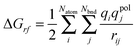 | (1) |
where
Nbnd is the number of induced surface charges and
rij is the distance between atom
i and induced surface charge
j. Similar to the treatment of the reaction field energy, induced surface charges can be used to improve the convergence of reaction field forces
via a pairwise summation of the Coulombic interactions between induced surface charges and atomic charges.
74 In addition, it has been shown that the dielectric boundary forces can be recast into a form involving induced surface charges as follows,
75| | 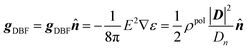 | (2) |
where
ρpol is the induced charge density at the dielectric boundary,
D =
εE, and
Dn =
εEn.
Eqn (2) does not require a differentiable dielectric constant distribution, leading to a better numerical behavior in force calculations.
Given these interesting numerical properties using induced surface charges, we intend to explore their usage directly in the FDM solution of the PBE to achieve a higher level of consistency between the numerical solution of the PBE and its post analysis. There are also additional motivations to adopt the “charge-central view”. First, it allows a second-order accurate numerical solver, the immersed interface method,76,77 to be used in the general finite-difference framework in a memory-efficient manner due to the use of the two-dimensional unknowns (induced surface charges) instead of the three-dimensional unknowns (spatial potential) within the core iteration. Apparently this argument also applies to the associated coefficient matrices.44 Higher-order accuracy is also possible given the underlining framework of the immersed interface method.76,77 Next the method can also be extended to the piecewise-smooth dielectric models instead of the widely used piece-wise constant dielectric constant models to facilitate the development of more physical dielectric models. Thus, the new strategy can be regarded as an improvement over the traditional BEM methods where their direct usage in numerical solutions was originally proposed. Finally the absence of a dielectric interface upon the introduction of the induced surface charge also allows highly efficient Poisson solvers, in terms of both memory and time, to be adopted in the new numerical framework.
In the following, we first review the charge central view of the PBE solution. This is followed by the presentation of the augmented immersed interface method76,77 to realize the direct solution from the charge central view within the FDM framework. Detailed numerical analysis of the new method in both analytical systems and realistic biomolecules is then presented to assess its performance. This is followed by the discussion of limitations and future directions.
Theory
In this section we first present the charge central formulation for solvated biomolecules modeled by the Poisson equation. This is followed by the charge central strategy for the Poisson–Boltzmann equation. As will be shown, the basic idea of this strategy is the introduction of a hypothetical induced surface charge distribution, which effectively removes the discontinuous dielectric constant across the solvent–solute interface.Poisson equation
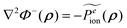
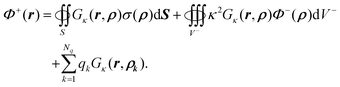
In the classical electrostatic solvation model, the molecular solute is approximated as a low dielectric region Ω− with dielectric constant ε− and the continuum solvent is represented as a high dielectric region Ω+ with dielectric constant ε+. The interface separating the two regions is denoted Γ. A number (Nq) of fixed interior point charges Qk are located at atomic centers ρk. Given the mathematical setup, the electrostatic potential Φ(r) can be uniquely determined by the following partial differential equations| | 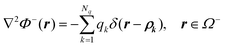 | (3) |
andgiven a set of well-defined boundary conditions. Here δ(x) is the Dirac delta function, qk = Qk/ε−, and r is an arbitrary position vector in the inner region or the outer region. The boundary conditions at the interface r ∈ Γ are| | 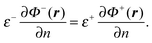 | (6) |
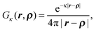
Apparently the potential at the outer boundary of Ω+ is also required. Here the free-boundary condition, i.e. potential goes to zero at infinity, is used.The fundamental solution for the Poisson equation with the specified free boundary condition is the free-space Green's function, G0(r,ρ) = 1/(4π|r − ρ|), satisfying
| | | ∇2G0(r,ρ) = −δ(r − ρ), | (7) |
and the same free space boundary condition. Based on Green's second identity and the boundary element theory as in Appendix A.1, it is straightforward to show that
| | 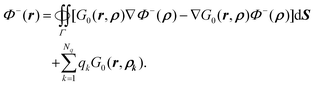 | (8) |
The above equation can be rewritten as
| |  | (9) |
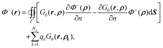
given that (1) the potential is continuous across the interface and (2)

on the interface for any smooth function
φ± within each region. The symmetrical arrangement of the two terms in the integrand allows an induced surface-charge dependent term to be introduced. Recall that the surface charge can be written as
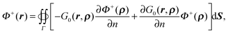
| | 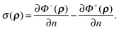 | (10) |
To do so, we apply the Gauss theorem to the second term in
eqn (9) in the outer space as in Appendix A.2. Thus,
| | 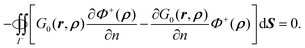 | (11) |
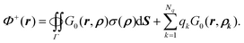
From
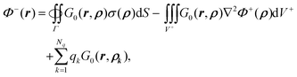
eqn (9) and (11), the inner potential can then be written as
| |  | (12) |
where
ρ ∈
Γ and
r ∈
Ω−.
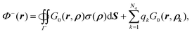
Similarly for the potential in the solvent region, Φ+(r), we have
| |  | (13) |
where
ρ ∈
Γ and
r ∈
Ω+. Following the same derivation, it can be shown that
| |  | (14) |
In summary,
| | 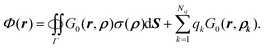 | (15) |
Thus the potential everywhere in the domain can be viewed as the contributions from both the fixed charges and the induced surface charges on the interface. Note also that the discontinuous or variable dielectric constants are no longer explicitly present in the formulation.
Poisson–Boltzmann equation
In the PBE an extra term responsible for the mobile ions in the outer solvent region Ω+ is introduced. The general PBE is| | | ∇·(ε(r)∇Φ(r)) = − ρ(r) − ∑n0iqi exp(−βqiΦ(r)), | (16) |
where n0i is the number density of counterions of type i in the solution, qi is the charge of the counterions of type i, and β = 1/kT. Here k is the Boltzmann constant and T is the temperature. When the ion concentration is low and the field is weak, the PBE can be linearized into the linear PBE:| | | ∇·(ε(r)∇Φ(r)) = − ρ(r) + ∑βni2qi2Φ(r). | (17) |
Apparently in the inner solute region Ω−, it is still the same as Poisson's equation described in the previous subsection. Since there is no fixed charge in the outer region Ω+, eqn (17) can be rewritten aswhere κ2 = ∑βni2qi2.The fundamental solution for the linear PBE with the free boundary condition is
| |  | (19) |
satisfying
| | | (∇2 − κ2)Gκ(r,ρ) = −δ(r − ρ). | (20) |
As shown in Appendix A.3, the inner potential can be written in terms of induced surface charge, as defined in
eqn (10), as
| |  | (21) |
where
ρ ∈
Γ and
r ∈
Ω−.
Eqn (21) can be further rewritten as
| | 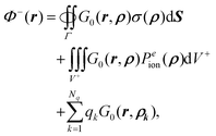 | (22) |
where we have made the substitution of ∇
2Φ+(
ρ) = −
Peion(
ρ),
i.e. by explicitly representing the outer potential as satisfying Poisson's equation with an apparent source of
Peion(
ρ) in
Ω+.
As shown in Appendix A.4, we can also obtain a similar expression for the potential in the solvent region as
| | 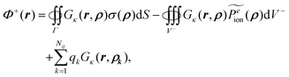 | (23) |
after taking ∇
2Φ−(
ρ) =
κ2Φ−(
ρ) and
into account.
Eqn (22) shows that the inner potential can be viewed as being contributed by the fixed atomic charges, induced surface charges, and mobile ion charges. Eqn (23) shows that a similar charge view can be formulated in the Yukawa field for the potential in the outer region: it can be viewed as being contributed by the fixed charges and the induced surface charges. Apparently in doing so, we have assumed that there is a uniform continuum mobile ion throughout the space. However this is not the case because the inner region does not have any mobile ion. Thus the extra term in eqn (23)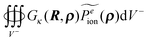 acts to compensate for the inclusion of the hypothetical mobile ion charge density in the inner region Ω−.
In the discussion above, we have suggested a charge-central view much similar to that used in the boundary element method49–64 to represent the solution of the linear PBE with discontinuous or variable dielectric constant distributions. Indeed, many boundary element methods were proposed following this strategy.49–64 In this study, a different charge-central strategy was explored within the finite-difference discretization framework, with the assistance of the augmented immersed interface method.76,77 There are several motivations to explore the new direction. First the immersed interface method is a second-order accurate approach, with the potential to go to higher orders as well. Second, the method can be extended to a piecewise-smooth dielectric model instead of the piecewise-constant dielectric constant model, which has become an interesting platform for more physical and more stable numerical solvation models. Finally the absence of a dielectric interface upon the introduction of the induced surface charge also allows highly efficient Poisson solvers, in terms of both memory and time, to be adopted in the new numerical framework.
Numerical algorithms
The theoretical discussion in the previous section suggests that the discontinuous dielectric constants can be eliminated by introducing the induced surface charges, which are essentially the boundary conditions for the normal electric fields on the interface. In the following we present a numerical technique to solve the Poisson equation by introducing additional variables, the induced surface charges, into the linear systems. These additional variables are termed augmented variables in the numerical algorithms. Thus the method is often referred to as the augmented approach.76,77 It should be pointed out that this is the first time the augmented immersed interface method is implemented and applied to realistic three-dimensional interface problems as complex as in macromolecules. A similar strategy can also be used to solve the Poisson–Boltzmann equation though it is far more complicated to be realized for biomolecular applications and is left to a future publication.The augmented approach
The original equations 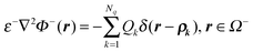 and ε+∇2Φ+(r) = 0, r ∈ Ω+ can be unified asgiven
| | 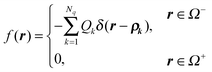 | (25) |
and| | 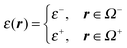 | (26) |
where ρk ∈ Ω−. Since ε is a piecewise constant in each domain, we can divide it from the above equation to obtain| |  | (27) |
Introducing a short-handed notation [f(x)]Γ = f+(x) − f−(x) where x ∈ Γ, i.e. the interface, we have the following boundary (interface) conditionsandEqn (27)–(29) show that solution Φ is clearly dependent on the two boundary conditions. The essence of the augmented approach is to introduce an auxiliary/augmented variable, σ = −[Φn]Γ, which acts as a new boundary condition in the solution of eqn (27) along with the boundary condition (28). Apparently the original boundary condition (29) must also be satisfied to be consistent with the original problem. This is achieved iteratively by verifying (29) after each trial solution of eqn (27).In the following we introduce Φ as discretized Φ, F as discretized f/ε, and Σ as discretized σ. Since the finite difference discretization is used, Φ and F are defined at the grid points. In contrast, discretized augmented variable Σ is apparently defined on the interface. For regular grid points, whose neighboring grid points are in the same region, eqn (27) can be discretized as
where ∇
h2 is the discretized Laplacian operator,
i.e. the symmetric seven-stencil finite-difference operator. For irregular grid points with any of the neighboring 26 grid points in the other region, the analytical boundary conditions are applied to derive the discretized equations. Here a set of interface points,
X1,
X2,
X3, …,
XNb, are used to discretize the interface so that both
Σ and boundary conditions
(28) and
(29) are defined at these interface points in the discretized system. With the immersed interface method,
44,77 the discretized form of
eqn (27) can be written as
| | | ∇h2Φijk = Fijk + Cijk | (31) |
at irregular grid points, where
Cijk is a correction term, chosen to minimize the local truncation error while satisfying the boundary conditions of
(28), potential continuity and (10), [
Φn]
Γ = −
σ.
44 Thus,
eqn (31) is the discretized Poisson's equation in vacuum with a revised source term of
Fijk +
Cijk.
Let A be the discretized Laplacian operator, ∇h2, applied to eqn (31), then we can express the discretized Poisson's equation as77
Since boundary condition
(28), that is, the continuity of potential, is explicitly enforced in the discretization, we only need to solve for
Σ so that boundary condition
(29),
i.e. the flux conservation condition, is also satisfied upon solving. We define the residual vector for the flux conservation condition as
| | | R(Σ) = [εΦn] = ε+Φ+n − ε−Φ−n. | (33) |
It is written as a function of
Σ because
eqn (32), or more specifically
C, is dependent on the boundary condition
Σ (discretized form of [
Φn]
Γ = −
σ). Next we exploit the fact that
Φ±n can be interpolated linearly from {
Φi,j,k} while enforcing the boundary conditions to further rewrite
(33) as a linear combination of
Φ and
Σ. Since boundary conditions
(28) and
(29) are both zero, we have
where
E+,
E−,
T+, and
T− are coefficients of the linear interpolation. Thus
eqn (33) can be written as
where
E =
ε+E+ −
ε−E− and
T =
ε+T+ −
ε−T−.
Now there are three sets of unknown variables C, Σ, and Φ in eqn (32) and (35). We can eliminate the correction term C using its dependence on the boundary conditions. Thus we can obtain the solution of the linear system (32) with two sets of unknown variables. Upon the finite-difference discretization by the immersed interface method, the dependence of C on the boundary conditions can be expressed as linear combinations of two boundary conditions, [Φn]Γ = −σ and [Φ]Γ = 0 at {Xk}.77 Since the value of [Φ]Γ is zero, symbolically C = −BΣ, where B is the linear coefficient matrix for Σ and does not need to be formed explicitly as explained later. Thus eqn (32) can be rewritten as
Recall that we intend to solve for the augmented variable Σ, satisfying R(Σ) = 0, while solving the linear system. Combining R(Σ) = 0 and eqn (36), the following matrix-vector form can be obtained
| | 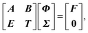 | (37) |
from which we can write its Schur complement as
| | | (T − EA−1B)Σ = −EA−1F. | (38) |
It may seem that the problem has been made more difficult because it is nontrivial to compute
T −
EA−1B and
EA−1F. However, we do not necessarily need to form these matrices explicitly. Instead the matrix-vector multiplication can be computed as shown below.
First let us focus on the right hand side, EA−1F. If we apply Σ = 0 to eqn (36), it is apparent that
Thus the right hand side of
eqn (38) can be transformed into
via the second expression
(35) for the residual vector,
R(
Σ) =
EΦ +
TΣ. Thus the right hand side is simply the residual vector when
Σ =
0. It can be further rewritten as a linear combination of potentials by the definition of residue
(33)| | | −EA−1F = −[ε+Φ+n(0) − ε−Φ−n(0)], | (41) |
where
Φ±n(
Σ =
0) is denoted
Φ±n(
0).
For the left hand side, T − EA−1B, the identity below can be obtained by substitution of BΣ from AΦ + BΣ = F in eqn (36) and A−1F = Φ(Σ = 0) in eqn (39)
| | | (T − EA−1B)Σ = [TΣ + EΦ(Σ)] − [T0 + EΦ(0)]. | (42) |
The second expression of the residual vector
R(
Σ) =
EΦ +
TΣ in
(35) shows that the two terms in parentheses are the residual vectors for
Σ ≠
0 and
Σ =
0, respectively. Therefore
T −
EA−1B can be computed as the difference between the two residual vectors. Finally given the residue definition in
eqn (33),
R(
Σ) =
ε+Φ+n −
ε−Φ−n, we can compute it as
| | | (T − EA−1B)Σ = [ε+Φ+n(Σ) − ε−Φ−n(Σ)] − [ε+Φ+n(0) − ε−Φ−n(0)]. | (43) |
In summary, the matrix-vector multiplication and the right hand side of eqn (38) can both be computed without much difficulty. Given these preparations, we are ready to use the GMRES algorithm to solve eqn (38) without forming matrix T − EA−1B explicitly.
GMRES
The Generalized Minimal Residual (GMRES)78 method is an efficient numerical method for solving a general linear system of equations in the form Ax = b, in which the matrix may not be symmetric or definite. The residual is defined as r = b − Ax for a solution vector x. GMRES is an iterative method that provides the best approximation of solution to Ax = b in the Krylov subspace {v1, Av1, …, An−1v1} with v1 = r0/∥r0∥ where r0 is the residual of the initial guess. An interesting property of the algorithm is that the matrix-vector multiplication Ax is required but it is not necessary to know matrix A explicitly.78 This is exactly the situation to solve for the augmented variables with the linear system (38). Given that Ax = (T − EA−1B)Σ and b = − EA−1F, the residual vector r = b − Ax is the difference between eqn (41) and (43),| | | −[ε+Φ+n(0) − ε−Φ−n(0)] − {[ε+Φ+n(Σ) − ε−Φ−n(Σ)] − [ε+Φ+n(0) − ε−Φ−n(0)]}. | (44) |
which is negative residue, −[ε+Φ+n(Σ) − ε−Φ−n(Σ)], based on the residual definition (33) in the augmented approach. Thus GMRES is well suited to solve the smaller linear system as outlined above.Computational details
We implemented the new method into the Amber/PBSA program.18,23,34,35 The molecular surface was defined using a revised density function strategy that combines the modified van der Waals surface and an optimized density function to mimic the solvent excluded surface as much as possible.16 In the modified van der Waals method a set of conformation-dependent atomic radii are first computed. This is followed by a standard van der Waals surface calculation. In doing so, the solvent accessible surface definition is effectively used for fully buried atoms and the van der Waals definition is used for fully exposed atoms.16 The density function is then applied to the modified van der Waals surface to further smooth out crevices intrinsic to the van der Waals surface definition. The atomic cavity radii were set to be the default mbondi set in the Amber package, except that all hydrogen radii were set to be 1.0 Å. The solvent probe was set to be 1.4 Å. A classical two-dielectric model was used to set the dielectric distribution where the region within the molecular surface is set to 1 and the region outside the molecular surface is set to 80. Grid spacing is default, 1/8 Å, if it is not explicitly specified in the testing of the new method.A revised ICCG (incomplete Cholesky conjugate gradient) solver was implemented to take into account the uniform dielectric constant environment when the charge central view is adopted in the solution of the partial differential equation. The augment variables are the surface charges, or the jumps of derivatives of potential on the interface. The surface potential derivatives and related boundary conditions are computed using a two-sided interpolation scheme as discussed in Appendix B. Due to the complex geometry of the molecular surface, projected points of certain neighboring irregular grid points can be very close to each other on the molecular surface. This facilitates sharing of the projection point on the interface if their original projection points are too close to each other based on a predefined cutoff distance. Doing so clearly reduces the dimension of linear system (38). More importantly the efforts reduce the computation burden in the interpolation computation at each projection point as well. In this study, a cutoff distance of h2 was used in the proximity search, leading to a dimension reduction from 17% to 34% among tested small molecules and proteins.
Results and discussions
We tested the new method with both analytical systems and realistic biomolecules to assess its accuracy and consistency with respect to the classical finite-difference method. In order to gain a comprehensive understanding of the method, we computed the reaction field energies, potential and field on the interface for the tested systems.Validation with analytical solutions
We first validated the implementation of the augmented immersed interface method (AUG), with several analytical systems: monopole, dipole, and quadrupole in a spherical cavity as their analytical solutions can be readily calculated. The algorithm was tested at different spacings from 1/2 Å all the way to 1/16 Å to study its convergence to the analytical solutions. As shown in Fig. 1, the unsigned relative errors of the results with respect to the analytical results are all below 1.1%. With decreasing grid spacing, the relative errors are consistently decreasing, reducing to lower than 0.15% at the grid spacing of 1/16 Å, indicating a high level of agreement with the analytical solutions.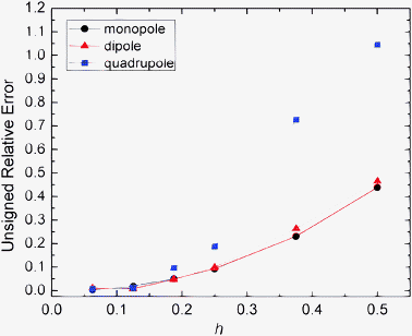 |
| | Fig. 1 Unsigned relative error (%) of reaction field energies (AUG method) with respect to analytic solutions versus grid spacing (h, Å) for monopole, dipole, and quadrupole respectively. Monopole: a single charge located at (0.5, 0, 0) in a sphere of radius 2 Å, dipole: two charges located at (0, 0, 0.5) and (0, 0, −0.5) respectively, quadrupole: four charges located at (−0.5, −0.5, 0), (0.5, 0.5, 0), (−0.5, 0.5, 0, 0), and (0.5, −0.5, 0) respectively. | |
Agreement with the classical method on small molecules and proteins
The new method was next tested on 41 small molecules, for which a fine grid spacing of 1/8 Å can be used, to reduce the difference in convergence of different methods but still at a reasonable computational cost. Correlation between reaction field energies by the new method and the classical weighted harmonic average method (WHA) was analyzed for the tested molecules. The deviations were also monitored. As shown in Fig. 2, an overall excellent agreement between the two methods can be observed. The deviation analysis shows that the relative deviations are below 0.25% at the tested condition, demonstrating the consistency of the new and classical methods in the computation of reaction field energies. To further evaluate the new method's consistency with the classical method on macromolecules, we selected eight small proteins, for which a grid spacing of 1/4 Å can be used. As shown in Table 1, the relative deviations between the two methods are all below 1%, with most of them below 0.5%, further confirming the consistency between the two methods in energy calculation.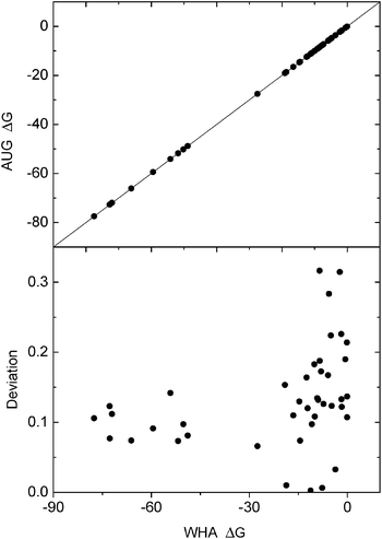 |
| | Fig. 2 Consistency of reaction field energies (ΔG, kcal mol−1) calculated by the AUG and WHA methods for small molecules. Upper: correlation of the reaction field energies between AUG and WHA at grid spacing 1/8 Å, lower: deviation (%) with respect to energies by the WHA method versus energies by the WHA method. The line in the upper graph is y = x. | |
Table 1 Consistency of reaction field energies (kcal mol−1) by the AUG (augmented immersed interface) and WHA (weighted harmonic average) methods at a grid spacing of 1/4 Å on eight selected small proteins
| Protein | WHA | AUG | Dev (%) |
|---|
| 1bbg | −496.107 | −492.467 | 0.734 |
| 1bgk | −986.515 | −982.895 | 0.367 |
| 1bh4 | −296.928 | −295.184 | 0.587 |
| 1ce4 | −672.381 | −669.528 | 0.424 |
| 1chl | −633.661 | −635.826 | 0.342 |
| 1erc | −850.308 | −846.281 | 0.474 |
| 1ica | −665.913 | −663.061 | 0.428 |
| 1svf | −506.114 | −503.612 | 0.494 |
Convergence of reaction field energy on realistic molecules
Given the above validation and consistency analyses, we went ahead to analyze the convergence behavior for two hydrogen-bonding base pairs adenine–thymine (AT) and guanine–cytosine (GC) and two salt-bridging side chain pairs arginine–aspartic acid (RD) and lysine–aspartic acid (KD), respectively. These small molecular systems were chosen in order to use the very fine grid spacing up to 1/16 Å in the analysis. The convergence trend was quantified with a nonlinear fitting of y = a + bxc for the numerical reaction field energies for each test case. As shown in Fig. 3, the computed energies converge as grid spacing is reduced as expected. And Table 2 lists detailed curve fitting statistics, which shows that the leading convergence orders range from 1.173 to 1.825 for the four tested small systems.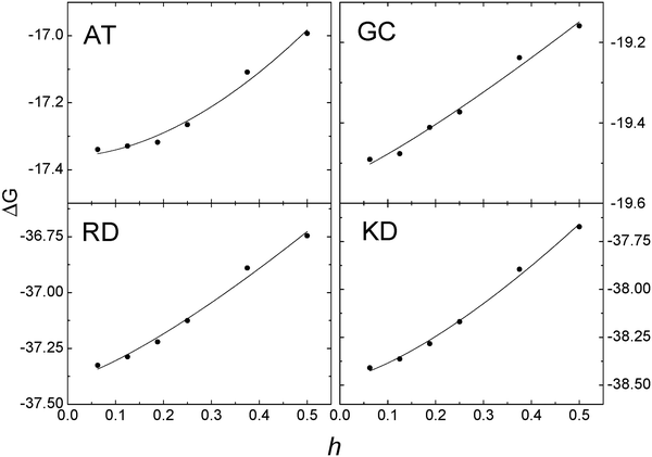 |
| | Fig. 3 Convergence of reaction field energies (ΔG, kcal mol−1) of the AUG method versus grid spacing (h, Å) on hydrogen-bonding base pairs AT and GC and salt bridging side chain pairs RD and KD, respectively. Solid lines: y = a + bxc fitting for the AUG method. | |
Table 2 The coefficients for nonlinear curve fitting, y = a + bxc, for the reaction field energies of AT, GC, RD, and KD, respectively, in Fig. 3
| | a | b | c |
|---|
| AT | −17.36 | 1.340 | 1.825 |
| GC | −19.54 | 0.874 | 1.173 |
| RD | −37.39 | 1.611 | 1.285 |
| KD | −38.47 | 2.150 | 1.406 |
Convergence of surface potential and field
An important motivation for developing the new method is to improve the convergence of surface field calculation to achieve more accurate solvation forces in biomolecular simulations. Here we analyzed the quality of numerical surface field by the new method with the same analytical systems of monopole, dipole, and quadrupole used to validate the method in energy computation. As shown in Fig. 4 and 5, the RMS errors of the potentials and field vectors with respect to analytical results decrease with reduced grid spacing. Furthermore, RMS errors of the new method are always smaller than those of the classic method for all tested conditions, indicating the benefit of imposing interface conditions in the new method.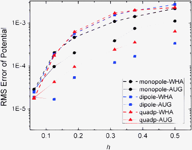 |
| | Fig. 4 RMS errors of potential (kcal mol−1 Å−1) versus grid spacing (h, Å) with respect to analytical results on the irregular grid points for the WHA and AUG methods of monopole, dipole, and quadrupole, respectively. | |
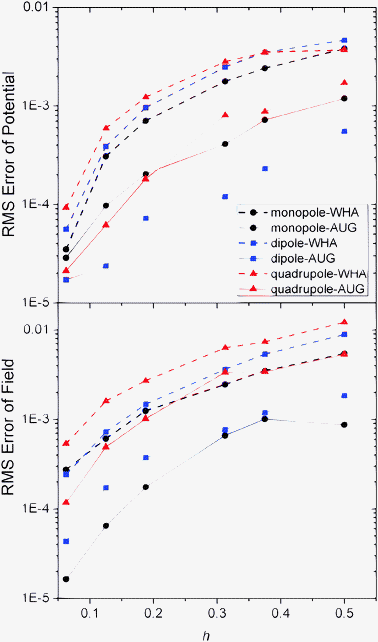 |
| | Fig. 5 RMS errors of potential (kcal mol−1 Å−1) versus grid spacing (h, Å) with respect to analytical results on the interface for the WHA and AUG methods (upper) and RMS errors of field (kcal mol−1 Å−2) on the inner side of the interface (lower) of monopole, dipole, and quadrupole, respectively. | |
The same analysis was next conducted for the two realistic but small molecular complexes (AT and RD) used for energy convergence analysis. Here due to the lack of analytical solution, we conducted the analysis in two steps. First the potentials on the irregular grid points at coarse grid spacings were compared with those calculated at the chosen fine grid spacing of 1/16 Å. As shown in Fig. 6, for the AT dimer, AUG behaves better than WHA when the grid spacing is reduced to 1/8 Å. For the RD dimer, AUG and WHA have almost the same RMS errors at all tested grid spacings. Next, the potential and field at the interface were compared with those calculated at the grid spacing of 1/16 Å in Fig. 7. The potentials show the similar conclusion as Fig. 6 and fields are almost the same for both AT and RD dimers. These results show that benefit of the new method is not that apparent at least at commonly used coarse grid spacings, i.e. as large as 1/4 Å.
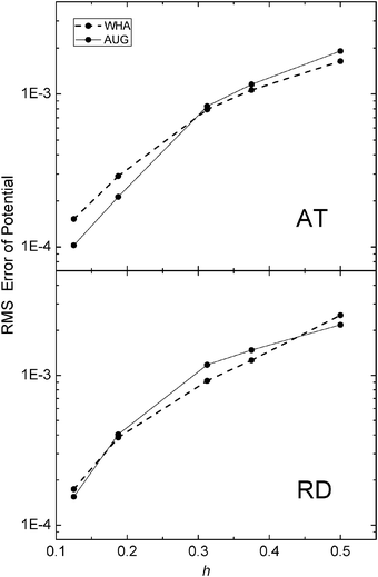 |
| | Fig. 6 RMS errors of potential (kcal mol−1 Å−1) versus grid spacing (h, Å) with respect to results calculated at the grid spacing of 1/16 Å on the irregular grid points of AT (upper) and RD (lower), respectively. | |
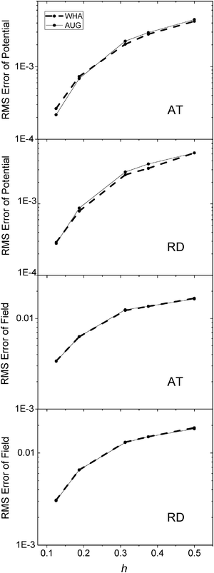 |
| | Fig. 7 RMS errors of potential (kcal mol−1 Å−1) (upper) and field (kcal mol−1 Å−2) (lower) versus grid spacing (h, Å) with respect to results calculated at the grid spacing of 1/16 Å on the inner side of the interface, of AT and RD, respectively. | |
Before going into detailed discussions to identify potential improvements, it is instructive to briefly review the overall algorithm flow again. As described in Numerical Algorithms, the new method follows a double-loop design. The outer loop in GMRES is responsible for the enforcement of boundary condition (29), i.e. flux conservation. The residue, (33), defined as the difference between the numerical boundary condition value and the theoretical value, is utilized to update the potential for the next iteration. The inner loop, an in vacuo Poisson solver, is responsible for solving the potential everywhere, given the updated right hand side from the GMRES outer loop.
The brief outline clearly shows that a major difference between the new method and typical finite-difference solvers is the extra outer loop. In typical numerical PB solvers, the potential obtained is the final result, but in the new algorithm, it is used again to update the numerical boundary condition to validate its agreement with the theoretical value. When deviation is higher than the preset convergence value, potentials are solved again to reduce it. This is clearly a more stringent requirement than the convergence criteria used in typical solvers, and bears the potential to reach higher accuracy.
However, the current implementation fails to demonstrate the significant benefit in realistic molecules. It is subject to debate that the following numerical instability issue has to be addressed to bring out the full potential of the new method. The limitation is in an interpolation procedure that is used to compute the boundary condition to validate the agreement with theoretical value. The difference is defined as the residue and it is utilized to update the potential in the next iteration, via the updated right hand side for the in vacuo Poisson solver. It is likely that the finite accuracy in the quadratic interpolation scheme utilized here (Appendix B) is propagated and accumulated in numerical potentials during the GMRES outer loop, reducing the desired second-order accuracy by design. Incidentally, the accuracy is clearly system dependent. Indeed, it works reasonably well for the simpler analytical spherical systems, but the quadratic approximation fails to bring out the potential of second-order accuracy in the more complex and realistic molecular environments, leading to no better performance on surface field and potentials than the classical method on the tested molecular systems.
Iteration tolerance analysis
A major difference between the new and classical methods is the different residue definition used in the iterative procedures. As described in Numerical Algorithms, the residue of the new method is defined as the agreement of the numerical boundary condition to the analytical one. In contrast, the residue of the classical method is defined as the agreement of the discretized potential in satisfying the discretized linear system, Ax = b. Thus it is necessary to assess to the proper choice of tolerance to obtain results with sufficient convergence to achieve the desired accuracy in the final potential. The tolerance analyses were conducted first for analytical systems, i.e. monopole, dipole, and quadrupole, respectively, in a spherical cavity. Fig. 8 summarizes the tests on the analytical systems, which indicates that the energy/potential error apparently depends on the tolerances used in the new method. The analysis also shows that a tolerance of 0.001 for the relative residue of the augment variable is quite sufficient since there is no noticeable change in the error of energy/potential upon tighter convergence tolerance.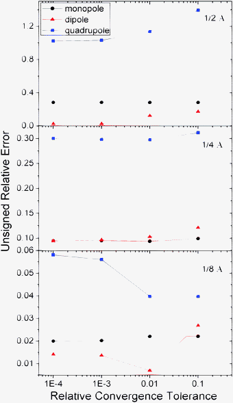 |
| | Fig. 8 Unsigned relative errors (%) of reaction field energies by the AUG method versus relative tolerance for monopole, dipole, and quadrupole, respectively. | |
The same test was also conducted for molecular dimers, AT, GC, RD and KD, respectively. As summarized in Fig. 9, it can be seen that a tolerance of 0.001 is again sufficient to achieve the desired error in energy/potential. And tighter tolerance does not improve the final accuracy of numerical energies noticeably.
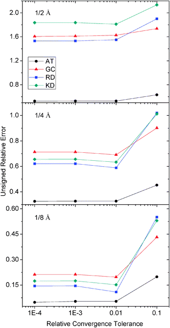 |
| | Fig. 9 Unsigned relative errors (%) of reaction field energies by the AUG method versus relative tolerance for AT, GC, RD and KD respectively. | |
Conclusion and future directions
Based on the analyses above, it is quite clear that it is feasible to solve the PBE directly via the use of induced surface charges and the new method is consistent with the classical method. On simpler analytical systems, we also observed better agreement with theory than the classical method given its second order accuracy by design. However, the benefit of the existing implementation is still not apparent for the solvent–solute interface properties in tested realistic biomolecular systems. Given the discussion of the potential limitation of our existing implementation, we are exploring to improve the surface interpolation procedure by using either a third or fourth order interpolation scheme to further reduce the numerical error in the computation of the residue vector in the GMRES iteration. In addition, we are in active development to adopt the efficient FFT Poisson solver for higher computational efficiency for systems where the periodic boundary condition must be used. Given these future developments, it will be interesting to compare the new method with other state-of-the-art methods.45–48Appendices
A. Theory
A.1. Derivation of inner potential. Based on Green's second identity| | 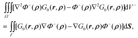 | (45) |
where on the left hand side of the equation ρ ∈ Ω− is the source position vector and r ∈ Ω− is the field position vector. Substitution of eqn (7) and (3) into eqn (45) leads to| | 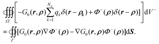 | (46) |
After rearrangement, we have| |  | (47) |
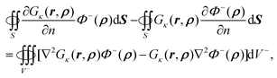
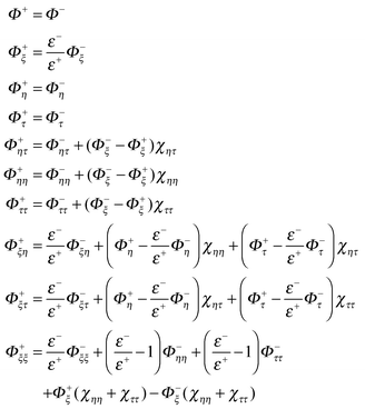
A.2. Proof of identity 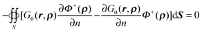 in (11). Given
| | | ∇·[G0(r,ρ)∇Φ+(ρ) − ∇G0(r,ρ)Φ+(ρ)] = G0(r,ρ)∇2Φ+(ρ) − ∇2G0(r,ρ)Φ+(ρ), | (48) |
where r ∈ Ω+ and ρ ∈ Γ. By integration of eqn (48) within the outer region,| | 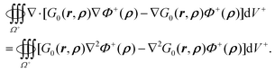 | (49) |
For the left hand side of eqn (49), use of the Gauss theorem in the outer space with boundaries at interface Γ and the infinity leads to| | 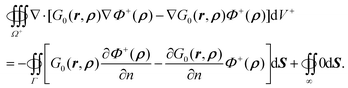 | (50) |
Here we have utilized the fact that both Φ+ and ∇Φ+ are zero at infinity. Since ρ ∈ Ω+, r ∈ Ω−, ∇2Φ+(ρ) = 0, and ∇2G0(r,ρ) = 0, the right hand sides of eqn (49) and also eqn (50) are equal to zero. Thus we have eqn (11)| | 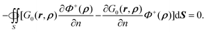 | (51) |
A.3. Derivation of inner potential for the PB equation. Similar to A.1 and A.2, though the difference is that ∇2Φ+(ρ) = 0 is no longer valid in the PB equation. Accordingly the right hand side of eqn (49) is no longer zero and the term 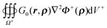 remains. Thus eqn (50) is rewritten as
| | 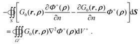 | (52) |
From eqn (9) and (52), the inner potential for the PB equation, can then be rewritten as| | 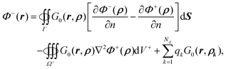 | (53) |
which is transformed into eqn (21) after introducing the induced surface charge as in eqn (10). A.4. Derivation of outer potential for the PB equation. Similar to A.2, given| | | ∇2Φ+(ρ)Gκ(r,ρ) − Φ+(ρ)∇2Gκ(r,ρ) = ∇·[Gκ(r,ρ)∇Φ+(ρ) − ∇Gκ(r,ρ)Φ+(ρ)], | (54) |
where r ∈ Ω+ and ρ ∈ Γ. By substituting the terms ∇2Gκ(r,ρ) and ∇2Φ+(ρ) using eqn (18) and (20), eqn (54) becomes| | | Φ+(ρ)δ(r − ρ) = ∇·[Gκ(r,ρ)∇Φ+(ρ) − ∇Gκ(r,ρ)Φ+(ρ)]. | (55) |
Integration in the outer region of both sides of eqn (55) yields| | 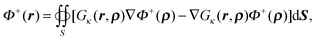 | (56) |
where r ∈ Ω+ and ρ ∈ Γ. It can also be rewritten as| | 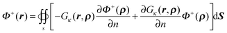 | (57) |
Given boundary condition (5), Φ+(r) can be further rewritten as| |  | (58) |
Application of Green's second identity to the right hand side in the inner region leads to
| |  | (59) |
where
r ∈
Ω+ and
ρ ∈
Ω− on the right hand side of the equation. Substitution of ∇
2Gκ(
r,
ρ) and ∇
2Φ−(
ρ) using
eqn (20) and (3) yields
| |  | (60) |
B. Interpolation of the derivative on the interface
A general interpolation scheme for approximating Φ−n(X) can be expressed as| | 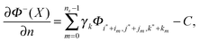 | (61) |
where  is the closest grid point to X,
  are other nearby grid points within a given cutoff distance, and C is a correction term. Note that we have omitted the dependence of {γk} and C on X for clarity. The interface where Φ−n(X) is defined can be expressed as ξ = χ(η,τ), with ξ as the normal direction and η and τ as the two orthogonal tangential directions.
If we use the local coordinate system centered at X and denote the local coordinates of  as (ξm,ηm,τm), we can express the Taylor expansion of Φ in the local coordinate system as
| | 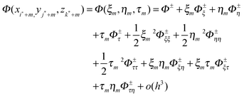 | (62) |
where
Φ±(
X) and its derivatives are yet to be determined. All the geometric properties,
i.e. the coefficients for the derivatives can be computed from the interface definition.
Substitution of (62) into (61) gives
| | | Φ−n (X) ∼ a1Φ− + a2Φ+ + a3Φ−ξ + a4Φ+ξ + a5Φ−η + a6Φ+η +a7Φ−τ + a8Φ−τ + a9Φ−ξξ + a10Φ+ξξa11Φ−ηη + a12Φ+ηη + a13Φ−ττ + a14Φ+ττ + a15Φ−ξη + a16Φ+ξτ + a17Φ−ητ + a18Φ+ητ + a19Φ−ξτ + a20Φ+ξτ − C | (63) |
where apparently
ai =
0 except
a5 =
1 because
ξ is the normal direction. The right hand side of
eqn (63) can be reduced to depend on the inner side properties only by using the following interface relations and their derivatives.
| |  | (64) |
After substitution of
eqn (61) into the left hand side of
eqn (63), and matching the coefficient of each derivative, a linear system for the coefficients {
γk} can be established. The number of equations above is 50 (10 for boundary conditions, 20 for relationship between {
ai} and {
γk}, 20 for
eqn (63) matching
ai =
0 except
a5 = 1), while the undermined coefficients are potentials and derivatives of potentials at projection points, {
ai} and {
γk}. We typically have an undermined system of linear equations that has an infinite number of solutions since only 27 grid points in the neighborhood are used. Thus the SVD algorithm is used to calculate {
γk}, and the SVD solution has the smallest 2-norm among all feasible solutions,
i.e.| | 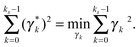 | (65) |
Acknowledgements
We are grateful to research support from NIH (R01GM093040 and R01GM79383).References
- M. E. Davis and J. A. McCammon, Chem. Rev., 1990, 90, 509–521 CrossRef CAS.
- K. A. Sharp, Curr. Opin. Struct. Biol., 1994, 4, 234–239 CrossRef CAS.
- M. K. Gilson, Curr. Opin. Struct. Biol., 1995, 5, 216–223 CrossRef CAS.
- B. Honig and A. Nicholls, Science, 1995, 268, 1144–1149 CrossRef CAS.
- B. Roux and T. Simonson, Biophys. Chem., 1999, 78, 1–20 CrossRef CAS.
- C. J. Cramer and D. G. Truhlar, Chem. Rev., 1999, 99, 2161–2200 CrossRef CAS.
- D. Bashford and D. A. Case, Ann. Rev. Phys. Chem., 2000, 51, 129–152 CrossRef CAS.
- N. A. Baker, Curr. Opin. Struct. Biol., 2005, 15, 137–143 CrossRef CAS.
- J. H. Chen, W. P. Im and C. L. Brooks, J. Am. Chem. Soc., 2006, 128, 3728–3736 CrossRef CAS.
- M. Feig, J. Chocholousova and S. Tanizaki, Theor. Chem. Acc., 2006, 116, 194–205 CrossRef CAS.
- W. Im, J. H. Chen and C. L. Brooks, Peptide Solvation and H-Bonds, 2006, 72, 173–198 Search PubMed.
- P. Koehl, Curr. Opin. Struct. Biol., 2006, 16, 142–151 CrossRef CAS.
- B. Z. Lu, Y. C. Zhou, M. J. Holst and J. A. McCammon, Commun. Comput. Phys., 2008, 3, 973–1009 Search PubMed.
- J. Wang, C. H. Tan, Y. H. Tan, Q. Lu and R. Luo, Commun. Comput. Phys., 2008, 3, 1010–1031 Search PubMed.
- A. Helgadottir and F. Gibou, J. Comput. Phys., 2011, 230, 3830–3848 Search PubMed.
- X. Ye, J. Wang and R. Luo, J. Chem. Theory Comput., 2010, 6, 1157–1169 Search PubMed.
- E.-H. Yap and T. Head-Gordon, J. Chem. Theory Comput., 2010, 6, 2214–2224 Search PubMed.
- J. Wang and R. Luo, J. Comput. Chem., 2010, 31, 1689–1698 CAS.
- W. Geng and G. W. Wei, J. Comput. Phys., 2011, 230, 435–457 Search PubMed.
- M. O. Fenley, M. Mascagni, J. McClain, A. R. J. Silalahi and N. A. Simonov, J. Chem. Theory Comput., 2010, 6, 300–314 Search PubMed.
- Z. Chen, N. A. Baker and G. W. Wei, J. Comput. Phys., 2010, 229, 8231–8258 Search PubMed.
- Q. Cai, J. Wang, H.-K. Zhao and R. Luo, J. Chem. Phys., 2009, 130, 145101 CrossRef.
- Q. Cai, M.-J. Hsieh, J. Wang and R. Luo, J. Chem. Theory Comput., 2010, 6, 203–211 CrossRef CAS.
- J. P. Bardhan, J. Chem. Phys., 2009, 130, 094102 Search PubMed.
- M. D. Altman, J. P. Bardhan, J. K. White and B. Tidor, J. Comput. Chem., 2009, 30, 132–153 Search PubMed.
- X. K. Chu, Y. Wang, L. F. Gan, Y. W. Bai, W. Han, E. K. Wang and J. Wang, PLoS Comput. Biol., 2012, 8 Search PubMed http://dx.doi.org/10.1371/journal.pcbi.1002608.
- I. Klapper, R. Hagstrom, R. Fine, K. Sharp and B. Honig, Proteins: Struct., Funct., Genet., 1986, 1, 47–59 CAS.
- A. Nicholls and B. Honig, J. Comput. Chem., 1991, 12, 435–445 CrossRef CAS.
- W. Rocchia, E. Alexov and B. Honig, J. Phys. Chem. B, 2001, 105, 6507–6514 CrossRef CAS.
- M. E. Davis and J. A. McCammon, J. Comput. Chem., 1989, 10, 386–391 CrossRef CAS.
- B. A. Luty, M. E. Davis and J. A. McCammon, J. Comput. Chem., 1992, 13, 1114–1118 CrossRef CAS.
- M. Holst and F. Saied, J. Comput. Chem., 1993, 14, 105–113 CrossRef.
- M. J. Holst and F. Saied, J. Comput. Chem., 1995, 16, 337–364 CrossRef CAS.
- R. Luo, L. David and M. K. Gilson, J. Comput. Chem., 2002, 23, 1244–1253 CrossRef CAS.
- Q. Lu and R. Luo, J. Chem. Phys., 2003, 119, 11035–11047 CrossRef CAS.
- W. Im, D. Beglov and B. Roux, Comput. Phys. Commun., 1998, 111, 59–75 CrossRef CAS.
- K. E. Forsten, R. E. Kozack, D. A. Lauffenburger and S. Subramaniam, J. Phys. Chem., 1994, 98, 5580–5586 Search PubMed.
- D. Bashford, Lect. Notes Compu. Sci., 1997, 1343, 233–240 Search PubMed.
- J. A. Meijerink and H. A. Vandervorst, Math. Compu., 1977, 31, 148–162 Search PubMed.
- I. Gustafsson, BIT Numerical Mathematics, 1978, 18, 142–156 Search PubMed.
- S. C. Eisenstat, SIAM J. Sci. Stat. Comput., 1981, 2, 1–4 Search PubMed.
- J. A. Meijerink and H. A. Vandervorst, J. Comput. Phys., 1981, 44, 134–155 Search PubMed.
- Z. H. Qiao, Z. L. Li and T. Tang, J. Comput. Math., 2006, 24, 252–264 Search PubMed.
- J. Wang, Q. Cai, Z. L. Li, H. K. Zhao and R. Luo, Chem. Phys. Lett., 2009, 468, 112–118 Search PubMed.
- Y. C. Zhou and G. W. Wei, J. Comput. Phys., 2006, 219, 228–246 Search PubMed.
- Y. C. Zhou, S. Zhao, M. Feig and G. W. Wei, J. Comput. Phys., 2006, 213, 1–30 Search PubMed.
- Y. C. Zhou, M. Feig and G. W. Wei, J. Comput. Chem., 2008, 29, 87–97 Search PubMed.
- D. A. Chen, Z. Chen, C. J. Chen, W. H. Geng and G. W. Wei, J. Comput. Chem., 2011, 32, 756–770 Search PubMed.
- S. Miertus, E. Scrocco and J. Tomasi, Chem. Phys., 1981, 55, 117–129 CrossRef CAS.
- H. Hoshi, M. Sakurai, Y. Inoue and R. Chujo, J. Chem. Phys., 1987, 87, 1107–1115 CrossRef CAS.
- R. J. Zauhar and R. S. Morgan, J. Comput. Chem., 1988, 9, 171–187 CrossRef CAS.
- A. A. Rashin, J. Phys. Chem., 1990, 94, 1725–1733 CrossRef CAS.
- B. J. Yoon and A. M. Lenhoff, J. Comput. Chem., 1990, 11, 1080–1086 CAS.
- A. H. Juffer, E. F. F. Botta, B. A. M. Vankeulen, A. Vanderploeg and H. J. C. Berendsen, J. Comput. Phys., 1991, 97, 144–171 CrossRef CAS.
- H. X. Zhou, Biophys. J., 1993, 65, 955–963 Search PubMed.
- R. Bharadwaj, A. Windemuth, S. Sridharan, B. Honig and A. Nicholls, J. Comput. Chem., 1995, 16, 898–913 Search PubMed.
- E. O. Purisima and S. H. Nilar, J. Comput. Chem., 1995, 16, 681–689 Search PubMed.
- J. Liang and S. Subramaniam, Biophys. J., 1997, 73, 1830–1841 CrossRef CAS.
- Y. N. Vorobjev and H. A. Scheraga, J. Comput. Chem., 1997, 18, 569–583 CrossRef CAS.
- M. Totrov and R. Abagyan, Biopolymers, 2001, 60, 124–133 Search PubMed.
- A. H. Boschitsch, M. O. Fenley and H. X. Zhou, J. Phys. Chem. B, 2002, 106, 2741–2754 CrossRef CAS.
- B. Z. Lu, X. L. Cheng, J. F. Huang and J. A. McCammon, Proc. Natl. Acad. Sci. U. S. A., 2006, 103, 19314–19319 CrossRef CAS.
- B. Lu, X. Cheng, J. Huang and J. A. McCammon, J. Chem. Theory Comput., 2009, 5, 1692–1699 Search PubMed.
- C. Bajaj, S.-C. Chen and A. Rand, SIAM J. Sci. Comput., 2011, 33, 826–848 Search PubMed.
- C. M. Cortis and R. A. Friesner, J. Comput. Chem., 1997, 18, 1591–1608 CrossRef CAS.
- M. Holst, N. Baker and F. Wang, J. Comput. Chem., 2000, 21, 1319–1342 CrossRef CAS.
- N. Baker, M. Holst and F. Wang, J. Comput. Chem., 2000, 21, 1343–1352 CrossRef CAS.
- A. I. Shestakov, J. L. Milovich and A. Noy, J. Colloid Interface Sci., 2002, 247, 62–79 Search PubMed.
- L. Chen, M. J. Holst and J. C. Xu, SIAM J. Numer. Anal., 2007, 45, 2298–2320 Search PubMed.
- D. Xie and S. Zhou, BIT Numerical Mathematics, 2007, 47, 853–871 Search PubMed.
- B. Lu and Y. C. Zhou, Biophys. J., 2011, 100, 2475–2485 Search PubMed.
- B. Lu, M. J. Holst, J. A. McCammon and Y. C. Zhou, J. Comput. Phys., 2010, 229, 6979–6994 Search PubMed.
- S. D. Bond, J. H. Chaudhry, E. C. Cyr and L. N. Olson, J. Comput. Chem., 2010, 31, 1625–1635 Search PubMed.
- W. Rocchia, S. Sridharan, A. Nicholls, E. Alexov, A. Chiabrera and B. Honig, J. Comput. Chem., 2002, 23, 128–137 CrossRef CAS.
- Q. Cai, X. Ye, J. Wang and R. Luo, Chem. Phys. Lett., 514, 368–373 Search PubMed.
- Z. Li, SIAM J. Numer. Anal., 1998, 35, 230–254 Search PubMed.
- Z. Li and K. Ito, The immersed interface method: numerical solutions of PDEs involving interfaces and irregular domains, Society for Industrial and Applied Mathematics, Philadelphia, 2006 Search PubMed.
- Y. Saad and M. H. Schultz, SIAM J. Sci. Stat. Comput., 1986, 7, 856–869.
|
| This journal is © the Owner Societies 2013 |
Click here to see how this site uses Cookies. View our privacy policy here.