Rapid determination of protein stability and ligand binding by differential scanning fluorimetry of GFP-tagged proteins†
Morgane J. J.
Moreau
a,
Isabelle
Morin
a,
Samuel. P.
Askin
a,
Alanna
Cooper
a,
Nicole J.
Moreland
b,
Subhash G.
Vasudevan
b and
Patrick M.
Schaeffer
*a
aComparative Genomics Centre, School of Pharmacy and Molecular Sciences, James Cook University, DB 21, James Cook Drive, Townsville, QLD 4811, Australia
bDuke-NUS Graduate Medical School, 8 College Rd, Singapore 169857. E-mail: patrick.schaeffer@jcu.edu.au; Fax: +61 (0) 7 4781 6078; Tel: +61 (0) 7 4781 4448
First published on 2nd October 2012
Abstract
The development of differential scanning fluorimetry and the high-throughput capability of Thermofluor have vastly facilitated the screening of crystallization conditions of proteins and large mutant libraries in structural genomics programs, as well as ligands in drug discovery and functional genomics programs. These techniques are limited by their requirement for both highly purified proteins and solvatochromic dyes, fueling the need for more robust technologies that can be used with crude protein samples. Here, we present the development of a new high-throughput technology for the quantitative determination of protein stability and ligand binding by differential scanning fluorimetry of GFP-tagged proteins. This technology is based on the principle that a change in the proximal environment of GFP, such as unfolding and aggregation of the protein of interest, is measurable through its effect on the fluorescence of the fluorophore. Protein stability data was generated for twelve GFP-tagged proteins including monomeric and multimeric, DNA-binding, RNA-binding, proteolytic, heat-shock and metabolic proteins of Escherichia coli, Burkholderia pseudomallei, Staphylococcus aureus, dengue and influenza (H5N1) viruses. The technology is simple, fast and insensitive to variations in sample volumes, and the useful temperature and pH range is 30–80 °C and 5–11 respectively. The system does not require solvatochromic dyes, reducing the risk of interference. The protein samples are simply mixed with the test conditions in a 96-well plate and subjected to a melt-curve protocol using a real-time thermal cycler. The data are obtained within 1–2 h and include unique quality control measures.
Introduction
The recent development of differential scanning fluorimetry (DSF) and the high-throughput capability of Thermofluor have vastly facilitated research in the field of macromolecular interactions.1–7 These techniques have already been implemented for the fast screening of crystallization conditions, in drug discovery programs and for the screening of large mutant libraries. The nature of DSF allows its use even when no information is available about the function of a protein of interest (POI). A further promising technology, based on thermal unfolding of GFP-tagged POI (GFP-Basta) was developed very recently.8,9 Although this simple technique requires a centrifugation step, it could potentially be used in high-throughput using adequate robotics. Both DSF-based techniques and GFP-Basta require only small amounts of recombinant proteins and are very useful to rapidly determine a protein's optimal storage or reaction conditions. The design of GFP-Basta allows it to be used with samples containing substantial amounts of additional proteins, i.e. ligands or contaminants, providing a unique tool to screen for the suitability of buffers before a purification step, or the study of a particular protein in a complex. Nevertheless, GFP-Basta suffers from the fact that it requires a separation step for its streamlining into a high-throughput technology.We previously observed that in the case of Tus-GFP, the binding of TerB DNA to the Tus domain significantly altered the fluorescence quantum of GFP (unpublished data). Building on this observation we hypothesized that any change in the proximal environment of GFP, such as unfolding and aggregation of the POI, should lead to a measurable change in fluorescence of the GFP.
Here we report the development of a radically new high-throughput technology for the quantitative determination of protein stability and ligand binding by differential scanning fluorimetry of GFP-tagged POI (DSF-GTP). The POI used for this study included the DNA replication terminator protein (Tus),10–13 single stranded DNA-binding protein (SSB),12 origin (oriC) binding protein (DnaA),12 glycerol kinase (GK)14 and chloramphenicol acetyl transferase (CAT)8,15,16 of Escherichia coli, the putative hydroperoxide reductase (HPR),17 proofreading DnaQ,18 DnaG primase18 and co-chaperonine (GroES)17 subunits of Burkholderia pseudomallei, the sortase (SRT)19,20 of Staphylococcus aureus, the RNA-dependent RNA polymerase (RdRp)21 of dengue virus (DV), and the nucleoprotein (NP)9 of influenza virus (IV) H5N1. These proteins were selected because they are currently the focus of several investigations in our lab due to their importance as potential drug targets,22–25 specific diagnostic antigens17 or as having great value in biotechnological applications.26–29 They were not preselected for their suitability as potential protein candidates to provide a totally unbiased study. A large amount of protein stability data as well as ligand-induced stabilization effects were generated for these proteins, demonstrating that DSF-GTP offers a unique and convenient strategy for the high-throughput determination of protein stability.
Experimental section
Cloning, protein expression and purification
Tus-GFP, GK-GFP, CAT-GFP, NP-GFP, SRT-GFP and GFP were prepared as previously described.8,9,30 The remaining POI (DnaA and SSB) encoding genes were amplified from E. coli DH12S, B. pseudomallei (K96243) genomic DNA (HPR (BPSL2096), GroES (BPSL2698), DnaQ (BPSL1341) and DnaG (BPSS1756)) and pET15b containing DENV3 (Genbank Accession AY662691) RdRp (aa273–900).21 Except for HPR-GFP and GroES-GFP, a GFP cloning cassette was used for cloning and production of fusion proteins following general cloning and Nickel-affinity purification procedures.8 See SI for PCR primer sequences and detailed expression and purification procedures. POI-GFP were in buffer A (50 mM sodium phosphate (pH 7.8)), buffer A2 (buffer A + 2 mM β-mercaptoethanol), buffer A10 (buffer A + 10 mM β-mercaptoethanol), buffer B (buffer A2 + 10% v/v glycerol) or buffer C (50 mM HEPES-KOH (pH 7.6), 1 mM EDTA, 20% sucrose, 1 mM β-mercaptoethanol) buffer D (50 mM Tris (pH 7.8), 0.1 mM EDTA, 0.2 mM β-mercaptoethanol) + 250 mM KCl and buffer E (20 mM Tris pH 8, 0.5 M NaCl, 1 mM EDTA, 1 mM β-mercaptoethanol, and 10% glycerol (v/v)).DSF-GTP
For all proteins, melting curves were obtained with an i-Cycler IQ5 (Biorad). The temperature range was 30–95 °C at 0.5 or 1 °C/cycle and 10 or 30 s dwell time depending on the POI. Specific settings are listed for each figure and in the relevant sections. Reactions were performed in triplicate with 20–60 μl of proteins at 2.5 μM yielding initial RFUs between ∼4000–8000. The Tm were determined by visual inspection of the melting curves and are listed in Table 1. Reaction conditions and effects of additives and ligands on Tm are also listed in Table 1 (see ESI† for detailed procedures).| Organism | POI-GFP | Buffer | Additive/Ligand | T m a (±SEM) °C |
|---|---|---|---|---|
| a For Tm determination, the temperature range was 35–90 °C at 0.5 °C/cycle and 30 s dwell time. When no Tm peak was identified and the residual fluorescence after a run with a temperature range of 35 °C to 75 °C (Ffold35-75) was > 0.85 an arbitrary value of >75 °C was attributed. Reaction conditions (20–60 μl of POI-GFP at ∼2.5 μM) were standardized to obtain starting RFUs of ∼4000–8000. | ||||
| E. coli | Tus | D | KCl (250 mM) | 44.3 (0.2) |
| KCl, TerB (3 μM) | 55.4 (0.6) | |||
| GK | A2 | — | 51.5 (0.1) | |
| ATP (3 mM) | 58.5 (0.0) | |||
| CAT | B | — | 72.5 (0.1) | |
| DnaA | C | MgCl2 (10 mM) | 51.9 (0.5) | |
| ATP (5 mM) | 44.7 (0.2) | |||
| SSB | E | — | >75 | |
| B. pseudomallei | HPR | A | — | >75 |
| GroES | A | — | >75 | |
| DnaQ | B | — | >75 | |
| DnaG | C | 52.8 (0.3) | ||
| S. aureus | SRT | A2 | — | >75 |
| Influenza H5N1 | NP | A2 | — | 72.6 (0.1) |
| Dengue virus | RdRp | A2 | — | 39.1 (0.0) |
| Aequorea victoria | GFP | A2 | — | 81.3 (0.0) |
| C | — | 84.5 (0.0) | ||
GFP-Basta
To confirm that Tm peaks were the result of protein aggregation, melting curves were stopped at the beginning, middle and end of peaks. Treated POI-GFP were kept on ice for 10 min before centrifugation at 18,000 g for 20 min. The residual fluorescence was measured as previously described for GFP-Basta.8Results and discussion
Concept and validation of DSF-GTP
We previously observed that the fluorescence intensity of TerB-bound Tus-GFP was increased compared to free Tus-GFP (unpublished data). This was surprising, as Tus and GFP are separated by a linker long enough (>5 unstructured residues)8 in the fusion protein to avoid the possibility of any interferences that would affect each of the domains' properties. As both protein domains unfold independently in the fusion protein, this phenomenon could only be the result of changes in the proximal environment of the GFP upon binding of TerB to the Tus domain—i.e. GFP acts as a sensor and reporter of its proximal environment. In this case, a change in fluorescence should also be measurable in real-time by DSF when Tus unfolds and aggregates (Fig. 1A). | ||
| Fig. 1 Concept and validation of DSF-GTP. A. The fluorescence of POI-GFP is monitored in real-time over a temperature range. At low temperature POI-GFP is in the fully folded state S1. POI-GFP switches to the lower fluorescent state S2 when POI unfolds and aggregates. Fluorescence is lost when GFP unfolds (S3 state). ΔF: difference in fluorescence. B. Melting curves obtained with Tus-GFP and GFP in buffer B. A peak is observed for Tus-GFP at ∼49 °C but not for GFP. C. Correlation between the Tm and the aggregation state of Tus-GFP. Reactions were stopped; immediately before, at the midpoint, and at the end of the Tm peak and centrifuged to discard aggregates. Residual fluorescence of the supernatants were quantified and plotted as fractions of folded protein (Ffold). The melting curve of Tus-GFP was plotted using the same temperature coordinates for comparison. D. Shift in the Tm of Tus-GFP upon binding to TerB in buffer D. E. Melting curves of Tus-GFP in buffer B. F. Melting curves of a mixture of Tus and GFP in buffer B at concentrations from 1.25-10 μM. Melting curves settings were: 0.5 °C/cycle and 10 s dwell-time for panels (B-C); 0.5 °C/cycle and 30 s dwell-time for (D); and 1 °C/cycle and 10 s dwell-time for (E-F). For (A-D) curves were obtained with Tus-GFP at 2.5 μM in reaction volumes of 20–60 μl. | ||
To test this hypothesis, we gradually heated a solution of Tus-GFP using the melting curve protocol of a real-time thermal cycler and compared the data with a control experiment (GFP alone). A transition in the melting curve could clearly be observed for Tus-GFP before loss of fluorescence of GFP at ∼80 °C. The curves were mathematically transformed to the first derivative to simplify their analysis (Fig. 1B). Here, the transition is visualized as a peak with its tip representing the transition midpoint (Tm). The transition in the melting curve was not visible with GFP, confirming that the effect is induced by the Tus domain in Tus-GFP (see GFP curve in Fig. 1B). We further investigated if the Tm peak was indeed a reflection of the aggregation stage of the Tus-GFP by comparing it to the residual fluorescence (Ffold) of reactions stopped at specific time-points– i.e. at the start of the peak, at its maximum and at the end – using an independent method (GFP-Basta). The data confirmed that the Tm corresponded to the transition midpoint of aggregation (Tagg) of Tus-GFP (Fig. 1C). As expected, the binding of TerB to Tus-GFP in buffer D resulted in a significantly higher Tm (Fig. 1D). We were able to clearly detect a Tm peak for Tus-GFP at 1.25 μM in a 20 μl reaction (Fig. 1E), which is a 2-10-fold lower protein concentration than typically required for DSF. The phenomenon is best explained by a fluorescence quenching mechanism resulting from shielding of the fluorophore by the proximity of the Tus-aggregates. This is further supported by the fact that a small Tm peak was apparent for a mixture of Tus and GFP at 10 μM each corresponding to the Tagg of Tus-GFP (Fig. 1F). Thus, the fluorescence quenching is highly enhanced by the physical linking of Tus with GFP as it becomes only apparent at the highest concentrations tested for a mixture of Tus and GFP (cf.Fig. 1E-F). This further suggests that the system could be used in the presence of additional proteins at concentrations <10 μM.
Next we investigated if the temperature-induced quenching of the POI-GFP fluorophore was not unique to Tus-GFP. For this, GK-GFP was chosen because it had previously been studied by GFP-Basta.8 GK is an important metabolic enzyme that catalyzes the phosphorylation of glycerol with ATP. We decided to compare the stability of GK-GFP in the presence and absence of ATP. As expected, we obtained different Tm peaks for free and ATP-bound GK-GFP (Fig. 2A). As for Tus-GFP, we used GFP-Basta as an independent method to check if the Tm peaks were indeed correlated with the aggregation states of the free and ATP-bound GK-GFP by comparing them to the residual fluorescence of reactions stopped at specific time-points– i.e. before, at the maximum and at the end of the peaks. This was necessary due to the surprisingly low Tm (51.5 °C, Fig. 2A) we obtained for free GK-GFP in a phosphate-based buffer at pH 7.8 (buffer A2), which was in stark contrast with the Tm of 71.3 °C obtained in Glycine-NaOH (pH 9.5) by Koga et al.31 They also found that 50% of GK was inactivated after 20 min incubation at 58 °C in the same conditions. In our conditions, GK-GFP required a 30 min incubation at ∼50 °C to yield a 50% loss of fluorescence by GFP-Basta in phosphate buffer.8 The different buffer and protein concentration (10 μM vs 2.5 μM in our study) used by Koga et al. could explain the difference in Tm. Although, intuitively, we would have expected a higher Tm, we confirmed that the GK-GFP Tm corresponded to the Tagg of GK-GFP and that ATP binding was responsible for the shift in Tm to a higher temperature in our conditions (Fig. 2A and Table 1 for values). The effects of ATP as well as glycerol were further investigated by DSF-GTP to determine their respective binding constants (Kobs). Using a simple graphical analysis method (see ESI Fig. S1†), we estimated a Kobs of 14 μM for GK-GFP binding to glycerol in phosphate buffer at pH 7.8, which was in agreement with the KD (∼10 μM) reported by Thorner et al. at pH 7.0 in triethanolamine containing MgCl2 and β-mercaptoethanol.14 We also determined the Kobs for ATP (340 μM) which was similar to one of its reported KM values.14
 | ||
| Fig. 2 A. Correlation between the Tm peak and aggregation of GK-GFP in the absence or presence of 3 mM ATP. Reactions were stopped immediately; before, at the midpoint, and at the end of the Tm peak and centrifuged to discard aggregates. Ffold of the supernatants were quantified and plotted (open symbols). The melting curves of Tus-GFP expressed as dRFU/dT were plotted using the same temperature coordinates for comparison (closed symbols). B. Melting curves of POI-GFP producing a Tm peak. DnaG-GFP and NP-GFP were left out for clarity (see Table 1 for details). Melting curve protocol: 0.5 °C/cycle and 30 s dwell time. Reactions (20–60 μl) contained POI-GFP at 2.5 μM. | ||
Further validation studies were performed to obtain the Tm of the ten remaining POI-GFP included in this study. The POI-GFP were tested in different buffer conditions depending on their individual solubility requirements (Fig. 2B and Table 1). We could not observe Tm peaks for HPR-GFP, GroES-GFP, DnaQ-GFP, SRT-GFP and SSB-GFP. After measuring the residual Ffold immediately after the melting curve (35–75 °C) with GFP-Basta, we concluded that these proteins were either thermostable or refolders as they did not aggregate in our reaction conditions (Ffold35-75 >0.85, i.e. >85% soluble proteins after the heating cycle from 35–75 °C). Further investigations were abandoned for these proteins. Anecdotally, the putative HPR and GroES from B. pseudomallei have been identified as highly immunogenic.17 These data support the use of these antigenic markers in downstream diagnostic applications due to their extreme stability and solubility. The high thermal stability of the putative 3′–5′ proofreading DnaQ subunit of B. pseudomallei was more surprising as, although not directly comparable, a C-terminally truncated E. coli homolog has previously been shown to be rather unstable (50% remaining activity after 10 min incubation at 43 °C).32Tm could be recorded for the remaining proteins and ranged between ∼39 and 72.6 °C (cfTable 1 and Fig. 2B). Within the proteins that produced Tm peaks, DnaA-GFP was most remarkable as it did not produce a peak unless Mg2+ or ATP were added. Out of this initial screen, Tus-GFP, DnaA-GFP and RdRp-GFP were further investigated to highlight various applications of DSF-GTP, and the data is presented below.
Salt and pH-dependence of free and DNA-bound Tus-GFP
Tus is a key protein in various proteomic and diagnostic technologies8,26–28,30,33–37 albeit only not much data is available on its salt and pH-dependence. Surface plasmon resonance (SPR) had previously been used to measure the effect of KCl on the Tus-TerB interaction10,38 but the technique was impractical due to increasing non-specific interactions at salt concentrations <150 mM and its low-throughput. Here we aimed to compare the effect of KCl on free and DNA-bound Tus-GFP. We designed a screen consisting of eight concentrations of KCl ranging from 8.5–350 mM (buffer D with varying KCl) and compared the Tm of free Tus-GFP with four different DNA-bound forms (TerB, Ter-lockB, oriC and oriC-lock). The stability of free Tus-GFP increased almost linearly with increasing KCl concentrations (Fig. 3A). When Tus-GFP was bound to the non-specific oriC or oriC-lock, the stabilization effects were identical and started to be only visible at KCl <200 mM. The Tm progressively increased from ∼45–57 °C. As expected, for the specific TerB and Ter-lockB the stabilization effects were already visible at 350 mM KCl. In high-salt, the high-affinity binder Ter-lockB was more stabilizing than TerB but the difference narrowed progressively with decreasing KCl concentration. Then, below 200 mM KCl, TerB became increasingly more stabilizing than Ter-lockB. This change in trend is probably due to the fact that the Ter-lockB sequence is missing six nucleotides compared to the double-stranded TerB. The net increase in non-specific electrostatic interactions from six additional phosphodiester bonds and deoxyribose groups is likely to increase the affinity of Tus for TerB much more than for Ter-lockB in lower salt conditions. This is further supported by the increasing stabilization effects of oriC and oriC-lock on Tus-GFP in decreasing salt conditions. It had previously been shown that the ka was mainly affected by the ionic strength of the buffer for TerB.38 In a later report, it was shown that the difference in KD between rTerB and F5n-rTerB decreased with decreasing KCl concentration to the extent of being quasi identical at 100 mM KCl.10 Taking into consideration that our curves already cross at around 200 mM KCl – i.e. identical KD – this suggests that the ka of Tus for TerB increases much more than for Ter-lockB in decreasing KCl concentrations, which is probably the result of additional electrostatic interactions present in the Tus-TerB complex.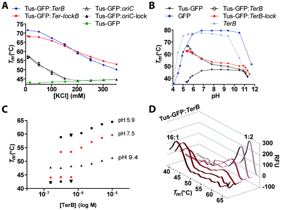 | ||
| Fig. 3 Comparison of the effects of KCl and pH on the stability of free and DNA-bound Tus-GFP. A. Effect of KCl. Melting curves were obtained for Tus-GFP, either free or bound to TerB, Ter-lockB, oriC or oriC-lock in buffer D with increasing KCl concentrations (8.5–350 mM). B. Effect of pH. Melting curves were obtained for Tus-GFP, either free or bound to TerB or Ter-lockB and GFP at pH ranging from 4–12. Melting curves were also obtained for TerB with SYBR green I in the same conditions. C. Effect of increasing concentrations of TerB on Tm of Tus-GFP. Tus-GFP (2.5 μM) was incubated at RT for 15 min with varying ratios of TerB at either pH 5.9, 7.5 or 9.4 (see Fig. S1† and Experimental Procedures for reaction conditions). D. Melting curve profiles obtained with different ratios of Tus-GFP:TerB at pH 5.9 (see also Fig. S1†). All reactions contained 2.5 μM of Tus-GFP. Melting curves were recorded from 35–80 °C with 0.5 °C/cycle and 30 s dwell time. | ||
Next, a pH screen was designed to identify the pH at which Tus-GFP is most stable in free and DNA-bound form, as well as the useful pH range of GFP (Fig. 3B) and the method. The pH-stability curves we obtained for free and bound Tus-GFP (TerB and Ter-lockB) by DSF-GTP were remarkable in that they afforded highly precise and sensitive protein stability data. The stability of Tus-GFP was constant in pH values ranging from 7–11 but dropped rapidly within one pH unit above and below this range. At pH <7.5, symmetrically opposed trends were observed for free and ligand-bound Tus. In fact, as Tus-GFP was gradually destabilized in decreasing pH, Tus-GFP-TerB and Tus-GFP-Ter-lockB were becoming increasingly more stable, reflecting a strong increase in their binding affinity and stability. The analysis was complicated for DNA-bound Tus-GFP as the GFP was gradually destabilized in lower pH. As a result, the Tus-GFP and the large GFP Tm peaks merged in the curve and limited the analysis to a minimal pH value of ∼5.5. We could not determine the optimal pH of the DNA-bound proteins below this value. More specifically, for TerB and Ter-lockB, the stabilization effects were visible even at high pH values although their effects were much less prominent than in lower pH. At the highest pH, Ter-lockB still had a stabilizing effect on Tus-GFP but not TerB. This difference in stabilization narrowed progressively with decreasing pH values. At pH ∼6.5 the curves crossed and below that value, TerB became increasingly more stabilizing than Ter-lockB. It has previously been shown that the affinity of a DNA-binding protein for DNA increases at low pH.39–42 This is also the case with the Tus-TerB and Tus-Ter-lockB complexes and can be explained by an increase in net positive charge of Tus (at low pH), strengthening the electrostatic interactions with the negatively charged phosphate backbone of the DNA. Thus, the difference in stabilization trends observed for Tus-GFP-TerB and Tus-GFP-Ter-lockB at low pH as well as at lower salt conditions is mainly due to the difference in number of nucleotides between these two species.
Concentration dependence of TerB on Tus-GFP and determination of Kobs
The concentration dependence of TerB on Tm of Tus-GFP was investigated to determine Kobs values in phosphate buffers (pH 5.9, 7.8 and 9.4) as well as in Tris buffers (buffer D + 250 mM KCl at pH 7.5 and 7.8). At pH 9.4, the Tm peaks of Tus-GFP shifted moderately to higher temperatures with increasing concentrations of TerB (Fig. 3C). At pH ≤7.8, the Tm shifted faster and with more amplitude with decreasing pH (Fig. 3C and supplementary Fig. S1†). At pH 5.9 (Fig. 3C) and in both Tris buffers at pH 7.5 (Fig. 3C) and 7.8 (supplementary Fig. S1†) two distinct peaks could be observed, corresponding to both free and TerB-bound Tus-GFP at a TerB![[thin space (1/6-em)]](https://www.rsc.org/images/entities/char_2009.gif) :Tus-GFP ratio of <1:2 (Fig. 3D). A small broad peak was even visible at TerB:Tus-GFP ratio of 1:8 in addition to the Tus-GFP peak, and the peak intensities corresponded to the expected ratio (Fig. 3D). A similar split of protein melting transition into two Tm has previously been observed for Hsp90 and CAII by thermal shift assay and a mathematical model was developed to fit these curves.43 The fact that both peaks corresponding to the bound and unbound Tus-GFP species are observed at pH 5.9 as well as pH 7.5 and 7.8 in buffer D immediately suggests that the KD of Tus-GFP-TerB complexes in these conditions are ≤10 nM.43 We fitted all curves obtained in the various conditions from pH 5.9-9.4 using our graphical analysis method (see Supplementary Information) and obtained Kobs values ranging from 0.3–450 nM respectively (see Supplementary Fig. S1†). Here, the KD value of 9 nM in buffer D (pH 7.5) correlated well with the KD of 11 nM that we obtained by SPR in the same conditions,13,36 demonstrating the reliability of our method.
:Tus-GFP ratio of <1:2 (Fig. 3D). A small broad peak was even visible at TerB:Tus-GFP ratio of 1:8 in addition to the Tus-GFP peak, and the peak intensities corresponded to the expected ratio (Fig. 3D). A similar split of protein melting transition into two Tm has previously been observed for Hsp90 and CAII by thermal shift assay and a mathematical model was developed to fit these curves.43 The fact that both peaks corresponding to the bound and unbound Tus-GFP species are observed at pH 5.9 as well as pH 7.5 and 7.8 in buffer D immediately suggests that the KD of Tus-GFP-TerB complexes in these conditions are ≤10 nM.43 We fitted all curves obtained in the various conditions from pH 5.9-9.4 using our graphical analysis method (see Supplementary Information) and obtained Kobs values ranging from 0.3–450 nM respectively (see Supplementary Fig. S1†). Here, the KD value of 9 nM in buffer D (pH 7.5) correlated well with the KD of 11 nM that we obtained by SPR in the same conditions,13,36 demonstrating the reliability of our method.
Specificity of cofactor and DNA binding on DnaA-GFP
DnaA is an essential protein in DNA replication initiation and has been identified as a potential drug target due to its vital interactions with other replisomal proteins.44 It is a ring-forming multimeric protein and is part of the AAA+ family. It requires ATP and Mg2+ to initiate DNA replication at oriC.12,45,46 Interestingly, no Tm peak was apparent for DnaA-GFP in the absence of Mg2+ (Fig. 4A). This is probably due to the fact that the apoprotein is in a heterogenous unstable oligomeric form in the absence of Mg2+ ions.47 Here, the rapid interconversion between the different oligomeric states of the apoprotein could result in a broadening of the peak to the extent that it would not be visible even, at low temperature. Nevertheless, the Tm peak observed in the presence of Mg2+ corresponded to the Tagg of DnaA-GFP (Fig. 4A). | ||
| Fig. 4 Thermal stability of DnaA-GFP. A. Correlation between the Tm peak and the aggregation state of DnaA-GFP in the presence of 10 mM MgCl2. Melting curves were stopped immediately; before, at the midpoint, and at the end of the Tm peak and centrifuged to discard aggregates (Ffold; squares). The melting curve of DnaA-GFP expressed as dRFU/dT is represented for comparison (diamonds). B. Effects of nucleotides and divalent cations on DnaA-GFP. C. Tm values of DnaA-GFP in the presence of nucleotides and divalent cations. D. Effect of DNA binding in the presence of ATP, MgCl2 or ATP/MgCl2. Reactions contained 60 μl of DnA-GFP at 2.5 μM. Initial RFUs were 3800–4700. Melting curves were recorded from 30–75 °C with 0.5 °C/cycle and 30 s dwell time. | ||
The divalent cation and nucleotide requirements of DnaA-GFP were investigated by designing a screen to determine their stabilizing effects. The effect of various ribonucleotides, deoxyribonucleotides and divalent cations were analyzed on DnaA-GFP's Tm (see supplementary Table S1†-S2†). These nucleotides have previously been studied with an indirect DNA replication initiation assay,48–50 but the direct effects of adenine nucleotides and some of their analogs on DnaA stabilization were only measured by light scattering,47 and no attempt was ever made to determine the Tm of DnaA. In our hands, none of the deoxyribonucleotides showed any significant stabilizing effects on DnaA-GFP (i.e. no peak was visible), demonstrating that the 3′OH group is critical for binding. Within the different forms of ribonucleotides tested, ATP was more stabilizing than AMPPNP, and ADP was the weakest stabilizer (Fig. 4B-C). GTP, cAMP, and GDP did not produce any visible peak. This demonstrated the stringent specificity of DnaA-GFP for ATP. A relatively broad Tm peak was also apparent with Mn2+ (Fig. 4B-C). All other divalent cations did not produce a peak and some of them, such as Ni2+, Cu2+ and Co2+, resulted in a loss of initial fluorescence suggesting a direct effect on the GFP fluorophore (see ESI Table S2†). When the combined effects of ATP or ADP and Mg2+ were analyzed, the Tm of DnaA was further stabilized in each case, suggesting cumulative stabilizing effects (Fig. 4B-C).
Finally, the binding of DnaA-GFP to a DNA sequence derived from the oriC genomic region containing an ATP-DnaA box in the absence or presence of either ATP, Mg2+ or both was investigated (Fig. 4D). In each case (ATP, Mg2+ and Mg/ATP) the binding of a stoichiometric amount of oriC stabilized DnaA-GFP further. A small stabilization of DnaA-GFP by ∼1.1 °C was observed in the presence of ATP. Although the Tm for DnaA-GFP in the presence of Mg2+ was lower than for Mg2+/ATP, the addition of oriC resulted in the same increase in Tm (ΔTm) in both cases of ∼3.1 °C. These ΔTm are very modest, suggesting that the binding of the oriC oligonucleotide containing only one ATP-DnaA box is weak.
Stabilizing additives and ligand specificity of Dengue virus RNA-dependent RNA polymerase (RdRp)
DENV non-structural protein 5 (NS5) is bifunctional and comprises an N-terminal methyltransferase domain and a C-terminal RdRp catalytic domain within residues 270–900. RdRp is essential for replication of the positive-strand RNA genome catalyzing both the synthesis of minus-strand RNA template and subsequent additional plus-strand genomes. The structure of RdRp has been determined by X-ray crystallography21 revealing fingers, palm and thumb domains characteristic of other known polymerase structures and, rather unusually, two zinc-binding pockets in the fingers and thumb subdomain, respectively.Here the stabilizing effects of NaCl and/or ammonium sulfate (AS; 0, 100, 300 or 500 mM) and glycerol (0–30%) on RdRp-GFP have been assessed using DSF-GTP. Cumulative effects were observed for either NaCl with glycerol or AS with glycerol but no further stabilization occurred when both salts were combined, with a maximum stabilization of RdRp-GFP by ∼10 °C in 30% glycerol and 500 mM salt (Fig. 5A). Even moderate levels of AS (100 mM) and glycerol (7.5%) stabilized the protein by ∼5 °C and these conditions were used to examine the effect of ZnSO4 and MgSO4 on RdRp-GFP stability (Fig. 5B). Mg2+ has an essential catalytic role complexing with nucleotide tri-phosphates during RNA synthesis.51 However, even at 1 mM, MgSO4 did not stabilize RdRp, probably because Mg2+ binding requires co-ordination with both a catalytic aspartic acid (Asp-533) and the phosphate groups of an accompanying nucleotide. In the RdRp crystal structure, two zinc-binding domains are buried within the protein and likely have structural roles.21 Lower concentrations of zinc (1 and 10 μM) did not affect RdRp-GFP but high concentrations (100 μM) destabilized it by ∼6 °C. No zinc was added during the purification process but the absence of a zinc stabilization effect implies these binding sites were already occupied. As previously suggested by Yap et al.,21 RdRp may sequester zinc from the bacterial growth media. This is further supported by the destabilizing effect of 1 mM EDTA. The destabilizing effect of high concentrations of zinc could then be explained by non-specific binding to the unfolded state of the protein rather than binding to its specific sites.52
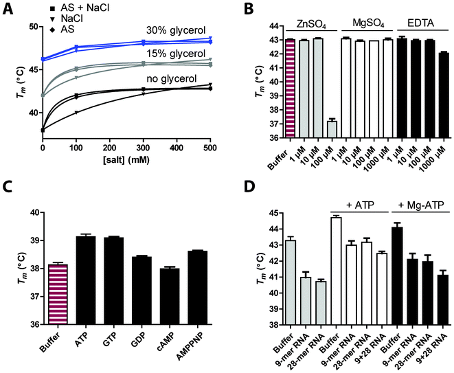 | ||
| Fig. 5 Effects of additives and ligands on RdRp-GFP stability. A. Combined effect of NaCl, ammonium sulfate (AS) and glycerol on RdRp-GFP (2.5 μM in phosphate buffer pH 7.8). B. Effect of ZnSO4, MgSO4 and EDTA. Increasing concentrations of additives were tested in phosphate buffer containing 7.5% glycerol and 100 mM AS. C. Effect of ribonucleotide binding. RdRp-GFP was diluted in phosphate buffer supplemented with 1 mM of ATP, GTP, GDP, cAMP or AMPPNP. D. Effect of RNA binding in the presence or absence of ATP or ATP/MgCl2. RdRp-GFP was diluted in phosphate buffer supplemented with 18.75% glycerol and equimolar concentrations of single-stranded RNA (9- or 28-mer) or partially double-stranded RNA (9 + 28 RNA). Each experiment was performed at least in triplicate. | ||
RdRp contains an NTP entry channel at the interface of the thumb and palm subdomains21 and high concentrations of GTP are required for de novo initiation by DENV RdRp.53,54 The addition of the nucleotide triphosphates ATP or GTP stabilised the Tm of RdRp-GFP (Fig. 5C) by ∼1 °C. Cyclic AMP had no effect and GDP had a smaller impact on the Tm than AMPPNP. Most interestingly, the addition of RNA destabilized RdRp-GFP by ∼2 °C with or without ATP or ATP/MgCl2 (Fig. 5D). The crystal structure for RdRp shows two flexible loops (L1 and L2) that lie over the RNA tunnel and link the fingers and thumb domain.21 In order for RNA to bind in the tunnel, a transition from a ‘closed’ to ‘open’ conformation must occur in which L1 and L2 flex apart. Further global motion of the enzyme likely occurs to accommodate RNA in the 30 Å deep tunnel. Our DSF-GTP data suggest this ‘breathing’ or opening of RdRp in the presence of RNA has a destabilizing effect on the enzyme.
Conclusions
DSF-GTP is simple, fast, robust and insensitive to variations in reaction volumes. Data are obtained within 1–2 h including manual handling by simply mixing a POI-GFP with a test condition and subjecting the mixture to a melt-curve protocol in a real-time thermal cycler. The useful temperature and pH range of the system is 30–80 °C and 5–11 respectively depending on the Tm of the POI and buffer conditions. The technology is well-suited for the study of protein–ligand interactions as it doesn't require solvatochromic dyes, eliminating the risk of interferences with additives, ligands or the protein itself. An advantageous and unique feature of DSF-GTP is that melting curves provide information on the effects of additives and buffers on fluorescence and stability of the GFP reporter itself, providing an in-built quality control measure for individual reactions. Thus, any discrepancy in buffer composition or POI-GFP concentration can be easily identified by comparing the initial fluorescence, Tm of GFP and peak area between experimental repeats. Finally, the expression and folding reporter function of the C-terminal GFP tag55 combined with its new function as a sensor for protein aggregation equips DSF-GTP with all the essential features to become a powerful and broadly applicable high-throughput tool for monitoring protein expression, folding, stability and ligand binding.Acknowledgements
This work was supported by grants to P.M.S. from Smart Futures Fund (National and International Research Alliance Program [NIRAP], Queensland, Australia).References
- F. H. Niesen, H. Berglund and M. Vedadi, Nat. Protoc., 2007, 2, 2212–2221 CrossRef CAS.
- G. A. Senisterra and P. J. Finerty Jr., Mol. BioSyst., 2009, 5, 217–223 RSC.
- U. B. Ericsson, B. M. Hallberg, G. T. DeTitta, N. Dekker and P. Nordlund, Anal. Biochem., 2006, 357, 289–298 CrossRef CAS.
- M. W. Pantoliano, E. C. Petrella, J. D. Kwasnoski, V. S. Lobanov, J. Myslik, E. Graf, T. Carver, E. Asel, B. A. Springer, P. Lane and F. R. Salemme, J. Biomol. Screening, 2001, 6, 429–440 CrossRef CAS.
- M. Vedadi, F. H. Niesen, A. Allali-Hassani, O. Y. Fedorov, P. J. Finerty, G. A. Wasney, R. Yeung, C. Arrowsmith, L. J. Ball, H. Berglund, R. Hui, B. D. Marsden, P. Nordlund, M. Sundstrom, J. Weigelt and A. M. Edwards, Proc. Natl. Acad. Sci. U. S. A., 2006, 103, 15835–15840 CrossRef CAS.
- J. J. Lavinder, S. B. Hari, B. J. Sullivan and T. J. Magliery, J. Am. Chem. Soc., 2009, 131, 3794–3795 CrossRef CAS.
- T. J. Magliery, J. J. Lavinder and B. J. Sullivan, Curr. Opin. Chem. Biol., 2011, 15, 443–451 CrossRef CAS.
- M. J. J. Moreau, I. Morin and P. M. Schaeffer, Mol. BioSyst., 2010, 6, 1285–1292 RSC.
- I. Morin and P. M. Schaeffer, Anal. biochem., 2012, 420, 121–126 CAS.
- M. D. Mulcair, P. M. Schaeffer, A. J. Oakley, H. F. Cross, C. Neylon, T. M. Hill and N. E. Dixon, Cell, 2006, 125, 1309–1319 CrossRef CAS.
- K. Kamada, K. Ohsumi, T. Horiuchi, N. Shimamoto and K. Morikawa, Proteins: Struct., Funct., Genet., 1996, 24, 402–403 CrossRef CAS.
- P. M. Schaeffer, M. J. Headlam and N. E. Dixon, IUBMB Life, 2005, 57, 5–12 CrossRef CAS.
- M. J. Moreau and P. M. Schaeffer, Mol. BioSyst., 2012, 8, 2783–2791 RSC.
- J. W. Thorner and H. Paulus, J. Biol. Chem., 1973, 248, 3922–3932 CAS.
- W. V. Shaw and A. G. W. Leslie, Annu. Rev. Biophys. Biophys. Chem., 1991, 20, 363–386 CrossRef CAS.
- T. Panchenko, W. W. Zhu and J. K. Montclare, Biotechnol. Bioeng., 2006, 94, 921–930 CrossRef CAS.
- P. L. Felgner, M. A. Kayala, A. Vigil, C. Burk, R. Nakajima-Sasaki, J. Pablo, D. M. Molina, S. Hirst, J. S. Chew, D. Wang, G. Tan, M. Duffield, R. Yang, J. Neel, N. Chantratita, G. Bancroft, G. Lertmemongkolchai, D. H. Davies, P. Baldi, S. Peacock and R. W. Titball, Proc. Natl. Acad. Sci. U. S. A., 2009, 106, 13499–13504 CrossRef CAS.
- M. T. Holden, R. W. Titball, S. J. Peacock, A. M. Cerdeno-Tarraga, T. Atkins, L. C. Crossman, T. Pitt, C. Churcher, K. Mungall, S. D. Bentley, M. Sebaihia, N. R. Thomson, N. Bason, I. R. Beacham, K. Brooks, K. A. Brown, N. F. Brown, G. L. Challis, I. Cherevach, T. Chillingworth, A. Cronin, B. Crossett, P. Davis, D. DeShazer, T. Feltwell, A. Fraser, Z. Hance, H. Hauser, S. Holroyd, K. Jagels, K. E. Keith, M. Maddison, S. Moule, C. Price, M. A. Quail, E. Rabbinowitsch, K. Rutherford, M. Sanders, M. Simmonds, S. Songsivilai, K. Stevens, S. Tumapa, M. Vesaratchavest, S. Whitehead, C. Yeats, B. G. Barrell, P. C. Oyston and J. Parkhill, Proc. Natl. Acad. Sci. U. S. A., 2004, 101, 14240–14245 CrossRef CAS.
- A. W. Maresso and O. Schneewind, Pharmacol. Rev., 2008, 60, 128–141 CrossRef CAS.
- T. Proft, Biotechnol. Lett., 2010, 32, 1–10 CrossRef CAS.
- T. L. Yap, T. Xu, Y. L. Chen, H. Malet, M. P. Egloff, B. Canard, S. G. Vasudevan and J. Lescar, J. Virol., 2007, 81, 4753–4765 CrossRef CAS.
- A. Agarwal, S. Louise-May, J. A. Thanassi, S. D. Podos, J. Cheng, C. Thoma, C. Liu, J. A. Wiles, D. M. Nelson, A. S. Phadke, B. J. Bradbury, M. S. Deshpande and M. J. Pucci, Bioorg. Med. Chem. Lett., 2007, 17, 2807–2810 CrossRef CAS.
- P. Soultanas, Structure, 2005, 13, 839–844 CrossRef CAS.
- S. Koepsell, D. Bastola, S. H. Hinrichs and M. A. Griep, Anal. Biochem., 2004, 332, 330–336 CrossRef CAS.
- Y. Zhang, F. Yang, Y. C. Kao, M. G. Kurilla, D. L. Pompliano and I. B. Dicker, Anal. Biochem., 2002, 304, 174–179 CrossRef CAS.
- S. P. Askin, I. Morin and P. M. Schaeffer, Anal. Biochem., 2011, 415, 126–133 CrossRef CAS.
- I. Morin, S. P. Askin and P. M. Schaeffer, Analyst, 2011, 136, 4815–4821 RSC.
- I. Morin, N. E. Dixon and P. M. Schaeffer, Mol. BioSyst., 2010, 6, 1173–1175 RSC.
- P. M. Schaeffer and N. E. Dixon, Aust. J. Chem., 2009, 62, 1328–1332 CrossRef CAS.
- D. B. Dahdah, I. Morin, M. J. J. Moreau, N. E. Dixon and P. M. Schaeffer, Chem. Commun., 2009, 3050–3052 RSC.
- Y. Koga, R. Katsumi, D. J. You, H. Matsumura, K. Takano and S. Kanaya, FEBS J., 2008, 275, 2632–2643 CrossRef CAS.
- S. Hamdan, E. M. Bulloch, P. R. Thompson, J. L. Beck, J. Y. Yang, J. A. Crowther, P. E. Lilley, P. D. Carr, D. L. Ollis, S. E. Brown and N. E. Dixon, Biochemistry, 2002, 41, 5266–5275 CrossRef CAS.
- D. K. Chatterjee, K. Sitaraman, C. Baptista, J. Hartley, T. M. Hill and D. J. Munroe, PLoS One, 2008, 3, e3265 Search PubMed.
- S. J. Kaczmarczyk, K. Sitaraman, T. Hill, J. L. Hartley and D. K. Chatterjee, PloS One, 2010, 5 Search PubMed.
- K. Sitaraman and D. K. Chatterjee, Methods Mol. Biol., 2011, 723, 185–200 CAS.
- M. J. Moreau and P. M. Schaeffer, Analyst, 2012, 137, 4111–4113 RSC.
- S. P. Askin and P. M. Schaeffer, Analyst, 2012, 137, 5193–5196 RSC.
- C. Neylon, S. E. Brown, A. V. Kralicek, C. S. Miles, C. A. Love and N. E. Dixon, Biochemistry, 2000, 39, 11989–11999 CrossRef CAS.
- S. Hamimes, D. Bourgeon, A. Z. Stasiak, A. Stasiak and E. Van Dyck, Biochem. Biophys. Res. Commun., 2006, 344, 87–94 CrossRef CAS.
- R. Wessel, U. Ramsperger, H. Stahl and R. Knippers, Virology, 1992, 189, 293–303 CrossRef CAS.
- T. Torigoe, H. Izumi, Y. Yoshida, H. Ishiguchi, T. Okamoto, H. Itoh and K. Kohno, Nucleic Acids Res., 2003, 31, 4523–4530 CrossRef CAS.
- Y. C. Peng and N. H. Acheson, J. Virol., 1998, 72, 7330–7340 CAS.
- A. Zubriene, J. Matuliene, L. Baranauskiene, J. Jachno, J. Torresan, V. Michailoviene, P. Cimmperman and D. Matulis, Int. J. Mol. Sci., 2009, 10, 2662–2680 CrossRef CAS.
- S. Fossum, G. De Pascale, C. Weigel, W. Messer, S. Donadio and K. Skarstad, FEMS Microbiol. Lett., 2008, 281, 210–214 CrossRef CAS.
- K. M. Carr and J. M. Kaguni, J. Biol. Chem., 2001, 276, 44919–44925 CrossRef CAS.
- K. M. Carr and J. M. Kaguni, J. Biol. Chem., 2002, 277, 39815–39822 CrossRef CAS.
- B. Banecki, J. M. Kaguni and J. Marszalek, Biochim. Biophys. Acta, Gene Struct. Expression, 1998, 1442, 39–48 CrossRef CAS.
- K. Sekimizu, D. Bramhill and A. Kornberg, Cell, 1987, 50, 259–265 CrossRef CAS.
- K. Sekimizu, D. Bramhill and A. Kornberg, J. Biol. Chem., 1988, 263, 7124–7130 CAS.
- P. Hughes, A. Landoulsi and M. Kohiyama, Cell, 1988, 55, 343–350 CrossRef CAS.
- H. Malet, N. Masse, B. Selisko, J. L. Romette, K. Alvarez, J. C. Guillemot, H. Tolou, T. L. Yap, S. Vasudevan, J. Lescar and B. Canard, Antiviral Res., 2008, 80, 23–35 CrossRef CAS.
- P. Cimmperman, L. Baranauskiene, S. Jachimoviciute, J. Jachno, J. Torresan, V. Michailoviene, J. Matuliene, J. Sereikaite, V. Bumelis and D. Matulis, Biophys. J., 2008, 95, 3222–3231 CrossRef CAS.
- M. Nomaguchi, M. Ackermann, C. Yon, S. You and R. Padmanbhan, J. Virol., 2003, 77, 8831–8842 CrossRef CAS.
- M. Nomaguchi, M. Ackermann, C. S. Yon, S. Y. You and R. Padmanabhan, J. Virol., 2003, 77, 10730–10730 CrossRef CAS.
- G. S. Waldo, B. M. Standish, J. Berendzen and T. C. Terwilliger, Nat. Biotechnol., 1999, 17, 691–695 CrossRef CAS.
Footnote |
| † Supplemental Table S1 and S2, Figure S1, extended experimental sections, curve fitting method and additional references. See DOI: 10.1039/c2ra22368f |
| This journal is © The Royal Society of Chemistry 2012 |