Noncovalent fabrication and electrochemical capacitance of uniform core–shell structured polyaniline–carbon nanotube nanocomposite
Haosen
Fan
abc,
Ning
Zhao
*a,
Hao
Wang
ab,
Yuhua
Long
ab,
Xiaofeng
Li
a and
Jian
Xu
*a
aBeijing National Laboratory for Molecular Sciences, Laboratory of Polymer Physics and Chemistry, Institute of Chemistry, Chinese Academy of Sciences, Beijing, 100190, P. R. China. E-mail: jxu@iccas.ac.cn; zhaoning@iccas.ac.cn; Fax: +86-10-62657919; Tel: +86-10-62657919
bGraduate University of the Chinese Academy of Sciences, Beijing, 100049, P. R. China
cSchool of Advanced Materials, Peking University Shenzhen Graduate School, Shenzhen, 518055, P. R. China
First published on 8th October 2012
Abstract
Highly uniform core–shell structured polyaniline–multiwall carbon nanotube nanocomposites have been successfully prepared by noncovalent coating of a polyaniline shell on the wall of MWNTs with the assistance of 1-pyrenesulfonic acid. It is found that 1-pyrenesulfonic acid plays important roles in dispersing MWNTs and directing the polymerization of the polyaniline shell by the sulfonic groups. The obtained nanocomposites exhibit a higher specific capacitance. This research provides a new approach for designing core–shell hybrid materials with potential application in high-performance electrochemical supercapacitors.
Introduction
As an energy storage device, electrochemical supercapacitors have attracted great interest due to their many potential applications, such as uninterrupted power sources, in electrical vehicles, and in other high-power apparatuses.1 For a supercapacitor, it is important and indispensable to choose a suitable electrode material with high capacity performance. Carbon materials,2 transition metal oxides3 and conducting polymers4 are the three main types of greatly investigated electrode materials. Carbon nanotubes, as one-dimensional nanomaterials, are excellent candidates for developing a new class of multifunctional composites owing to their unique structure and excellent mechanical and electrical properties.5 Recently, the study of nanocomposites of carbon nanotubes and conducting polymers has aroused great interest by combining the excellent properties of both components because of the special synergistic effect.6 Among the various structural conducting polymers, polyaniline (PANI) has attracted more and more attention because of its excellent properties such as low cost, facile synthesis, good environmental stability, outstanding electrical properties and different redox states.7 To date, various attempts have been made to integrate PANI and carbon nanotubes to obtain nanocomposites with excellent capacitive properties.8–11 In a general way, carbon nanotubes are usually treated in a strong inorganic acid to introduce functional groups (OH, C![[double bond, length as m-dash]](https://www.rsc.org/images/entities/char_e001.gif) O, or COOH) through liquid phase oxidation procedures.12 These oxygenated functional groups improve the good dispersability of carbon nanotubes in aqueous solutions or organic solvents and introduce active groups for the polymerization of aniline as well.13 However, acid oxidation methods will cause a large number of defects in the graphitic network of the sidewall of carbon nanotubes, which greatly impairs the physical and electrical properties of pristine carbon nanotubes.
O, or COOH) through liquid phase oxidation procedures.12 These oxygenated functional groups improve the good dispersability of carbon nanotubes in aqueous solutions or organic solvents and introduce active groups for the polymerization of aniline as well.13 However, acid oxidation methods will cause a large number of defects in the graphitic network of the sidewall of carbon nanotubes, which greatly impairs the physical and electrical properties of pristine carbon nanotubes.
In this paper, we present a simple method for the noncovalent functionalization of multi-walled carbon nanotubes (MWNTs) with 1-pyrenesulfonic acid (PSA). PSA can interact strongly with MWNTs via a π–π stacking interaction owing to its highly aromatic group14–17 by generating a stable aqueous suspension. Aniline monomers can complex with the sulfonic groups of PSA and then polymerize on the side walls of MWNTs by a chemical oxidation reaction, which implies that a good core–shell structure-based nanocomposite can be obtained while preserving the MWNTs perfect graphitic lattice and unique electronic properties. The specific capacitance of the obtained core–shell structured nanocomposite can reach as high as 619 F g−1 at a current density of 0.5 A g−1 in 1 M H2SO4 aqueous solution. It is suggested that the core–shell structured nanocomposite has a potential application as the electrode material of electrochemical supercapacitors for energy storage.
Experimental
Materials
Aniline (ANI, Beijing Chemical Co.) was distilled under reduced pressure. Ammonium persulfate (APS, Sinopharm Chemical Reagent Co.), commercial multiwall carbon nanotubes (MWNTs, 30–50 nm in diameter, 5–15 μm in length, purity ≥ 95 wt%, Shenzhen Nanotech Port Co., Ltd.), 1-pyrenesulfonic acid (PSA, Aldrich), 1-pyrenecarboxylic acid (PCA, Aldrich), 1,5-naphthalenedisulfonic acid (NSA, Aldrich), benzenesulfonic acid (BSA, Aldrich) and other reagents of A. R. grade were used without further treatment.Preparation of core–shell structured MWNTs@PANI
10 mg MWNTs powder was added into 20 mL deionized water and ultrasonicated for 10 min at room temperature, then 10 mL aqueous solution of PSA (1 mg mL−1) was added into the MWNTs suspension followed by sonication for 1 h. The resultant MWNTs–PSA complex was centrifuged and then washed with deionized water three times to obtain a clear filtrate. Aniline (0.2 mmol) was added into 20 mL dispersion of the above centrifuged MWNTs–PSA. After being stirred for 1 h, 10 mL aqueous solution of APS (0.2 mmol) was added and followed by stirring for 30 min. The reaction system was left at the stationary state for 12 h at room temperature. The resulting product was filtered and washed with water and methanol several times, and then dried under vacuum at 80 °C for 24 h. The final composite was named MWNTs@PANI. For comparison, PANI nanofibers were synthesized in 1 M HClO4 aqueous solution in the absence of MWNTs and PSA.Characterization
The morphology of all the products was characterized by transmission electron microscope (TEM, JEOL JEM-2200FS). UV-vis spectra were measured in aqueous solution on a Shimadzu 1601PC UV-vis spectrophotometer.Preparation of working electrode and electrochemical measurements
Electroactive nanocomposite (MWNTs@PANI), carbon black and poly(tetrafluoroethylene) in a mass ratio of 85![[thin space (1/6-em)]](https://www.rsc.org/images/entities/char_2009.gif) :10:5 were well mixed to obtain a homogeneous slurry. The slurry was coated and pressed on a foam nickel to prepare the working electrode, and then the electrode was dried at 60 °C for 24 h in a vacuum oven. For comparison, MWNTs and PANI electrodes were prepared with the same mass ratio and procedure, respectively. The electrochemical performance of all the samples was measured with a three electrode system, in which platinum foil and saturated calomel electrode (SCE) were used as counter and reference electrodes, respectively. The electrolyte is 1 M H2SO4 aqueous solution. Cyclic voltammetry (CV) and electrochemical impedance spectroscopy (EIS) measurements were studied using a Zahner IM6 electrochemical working station. EIS was recorded under the conditions of frequency range 0.01 to 105 Hz, AC voltage amplitude 5 mV, and with an excitation signal of 0.5 V. Galvanostatic charge–discharge was measured by a CHI 660 C electrochemical workstation.
:10:5 were well mixed to obtain a homogeneous slurry. The slurry was coated and pressed on a foam nickel to prepare the working electrode, and then the electrode was dried at 60 °C for 24 h in a vacuum oven. For comparison, MWNTs and PANI electrodes were prepared with the same mass ratio and procedure, respectively. The electrochemical performance of all the samples was measured with a three electrode system, in which platinum foil and saturated calomel electrode (SCE) were used as counter and reference electrodes, respectively. The electrolyte is 1 M H2SO4 aqueous solution. Cyclic voltammetry (CV) and electrochemical impedance spectroscopy (EIS) measurements were studied using a Zahner IM6 electrochemical working station. EIS was recorded under the conditions of frequency range 0.01 to 105 Hz, AC voltage amplitude 5 mV, and with an excitation signal of 0.5 V. Galvanostatic charge–discharge was measured by a CHI 660 C electrochemical workstation.
Results and discussion
Fig. 1 shows the schematic illustration of the formation of the MWNTs@PANI nanocomposite by the in situ polymerization of ANI in the MWNTs suspension with the assistance of PSA. Due to the π–π stacking interaction between the pyrene moiety of PSA and the graphitic structure of MWNTs, a stable aqueous suspension of MWNTs–PSA is obtained. The sulfonic groups of PSA on the wall of the MWNTs will dope the ANI and then direct the polymerization of ANI on the surface of MWNTs, leading to the formation of a uniform PANI layer on the side walls. In addition, the π–π stacking interaction between the aromatic or quinoid rings of PANI and the graphitic structure of MWNTs will also promote the formation of a compact PANI coating.18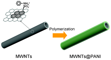 | ||
| Fig. 1 Schematic illustration of the formation of MWNTs@PANI nanocomposites. | ||
The typical morphology of the samples is shown in Fig. 2. The long tube MWNTs we used have an external diameter of about 50 nm with regular configuration of multiple graphite layers (Fig. 2a and b). From Fig. 2c and d, it can be seen that a MWNTs@PANI nanocomposite with clear and uniform core–shell structure is successfully fabricated and the thickness of PANI layer is about 20 nm.
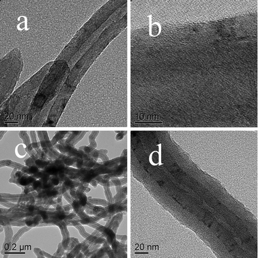 | ||
| Fig. 2 TEM images of MWNTs (a, b) and the resulting MWNTs@PANI nanocomposite (c, d). | ||
Fig. 3 shows spectroscopic monitoring of unbound PSA removal and UV-vis absorption spectra of PSA, MWNTs and MWNTs–PSA in aqueous solution, respectively. The original supernatant shows strong characteristic absorbance peaks of PSA due to the presence of unbound PSA, which is reduced in consecutive washing and centrifugation cycles. The amount of unbound PSA is greatly reduced in the supernatant of the third wash. The broad absorption peak of MWNTs–PSA in contrast to the nearly non absorption of MWNTs confirms the strong binding of PSA on the wall of the MWNTs.19 The binding of PSA on MWNTs increases the dispersiblity of MWNTs in aqueous solution, as shown in the inset photograph that most of the pure MWNTs were deposited at the bottom after keeping for 5 min while the MWNTs-PSA remain well disperses in the solution after standing for a week.
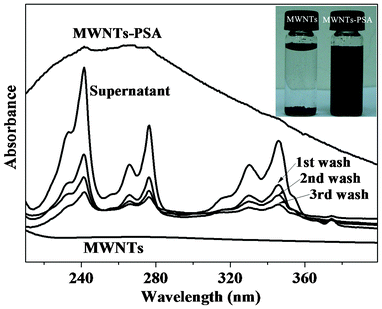 | ||
| Fig. 3 Spectroscopic monitoring of unbound PSA removal and UV-vis spectra of aqueous dispersions of MWNTs and MWNTs–PSA, respectively (inset is a digital photograph of aqueous suspensions of MWNTs and MWNTs–PSA). | ||
Fig. 4a exhibits the CV curves of the as-prepared electrodes at a scan rate of 5 mV s−1 in 1 M H2SO4 solution with a potential range of −0.2–0.8 V. In comparison to MWNTs and PANI electrodes, the MWNTs@PANI nanocomposite exhibits a larger current density response, indicating that the MWNTs@PANI electrode has a higher specific capacitance. The improved electrochemical performance of the MWNTs@PANI nanocomposite is due to the uniform core–shell structure and the synergistic effect between MWNTs and PANI by combining the high conductivity of MWNTs with the good redox properties of PANI. The MWNTs@PANI electrode shows obvious redox peaks in the CV curve, which are attributed to the redox transition of PANI from leucoemeraldine to polaronic emeraldine form and the transformation from emeraldine to pernigraniline.20
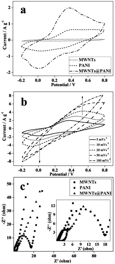 | ||
| Fig. 4 (a) CV curves of MWNTs, PANI and MWNTs@PANI electrodes at a scan rate of 5 mV s−1. (b) CV curves of MWNTs@PANI at different scan rates. (c) Niquist plots for MWNTs, PANI and MWNTs@PANI. | ||
Fig. 4b shows CV curves of the MWNTs@PANI nanocomposite at different scan rates from 5 to 100 mV s−1. The peak current density increases with the increase of potential scan rates, indicating a good rate property and excellent capacitance behavior for the MWNTs@PANI electrode.21 Meanwhile, due to the resistance of the electrode the anodic peaks shift negatively and the cathodic peaks shift positively with increasing potential scan rate.22
EIS is a powerful tool for the study of the characteristics of conductivity, structure and charge transport at the material–electrolyte interface. Fig. 4c shows the Nyquist diagrams for PANI, MWNTs and MWNTs@PANI nanocomposite, respectively. It can be seen that the plot for PANI shows a semicircle in the high-frequency region and a straight line in the low-frequency region which are attributed to the charge-transfer resistance of the electrode (Rct) and the internal resistance (Rs),23 respectively. Rct is one of the limiting factors for the power density of supercapacitors, corresponding to the charge-transfer resistance at the electrode–electrolyte interface. The diameter of the semicircle is the Rct. From the diameter of the semicircle on the real axis, it is obvious that the Rct of the core–shell structured MWNTs@PANI electrode reduces remarkably in comparison to pure PANI. Besides, the intercepts with the real axis at the high-frequency region provide quantitative information on the effective internal resistance (Rs). The low Rct and Rs of the MWNTs@PANI electrode make it possible for high power performance with higher specific capacitance.
The charge–discharge curves of MWNTs@PANI at different current densities (0.5, 1, 2 A g−1) within a potential range of 0 to 0.7 V are shown in Fig. 5a. The charge–discharge duration of the MWNTs@PANI composite increases with the current density varying from 2 to 0.5 A g−1. Charge–discharge curves keep a similar shape in the potential range of 0–0.7 V at these densities, indicating that the nanocomposite can experience a wide range of current. It is obvious that the charge–discharge does not show an ideal straight line with two clear voltage stages in the range of 0.45 to 0.7 V and 0 to 0.45 V, respectively, suggesting the process of a faradic reaction of the pseudo-capacitance.24 Besides, discharge–charge efficiency can be obtained according to the ratio of the discharge time to the charge time. the MWNTs@PANI electrode exhibits a high discharge–charge efficiency of 99.7% at a current density of 0.5 A g−1, which indicates excellent discharge–charge rate control capability and electrochemical reversibility. The specific capacitance of the electrode can be calculated from charge–discharge curves according to the equation Cm = C/m = It/ΔVm, where Cm is the specific capacitance based on the mass of electroactive materials, I is charge–discharge current, ΔV is 0.7, and m is the mass of the electroactive materials (g).25 The specific capacitance of the MWNTs@PANI at a current density of 0.5 A g−1 is 619 F g−1. The high specific capacitance of the MWNTs@PANI nanocomposite is due to a synergistic effect between the MWNTs and PANI and the uniform core–shell structure.
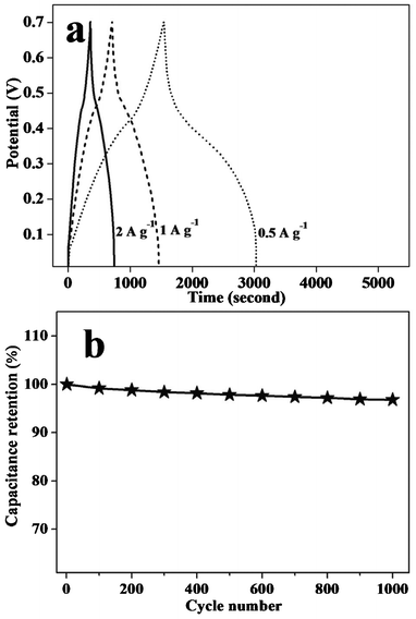 | ||
| Fig. 5 (a) Galvanostatic charge–discharge curves of MWNTs@PANI at a current density of 2, 1 and 0.5 A g−1 and (b) variation of the specific capacitance of MWNTs@PANI as a function of the cycle number. | ||
In order to further understand the electrochemical stability, the MWNTs@PANI electrode was measured by consecutive charge–discharge cycles at a current density of 2 A g−1 (Fig. 5b). It is found that the MWNTs@PANI electrode keeps 96.7% of its initial capacitance after 1000 cycle tests, suggesting that the MWNTs@PANI electrode exhibits excellent long-term cycle ability and a high degree of reversibility in consecutive charge–discharge cycles. Therefore, the MWNTs@PANI nanocomposite shows a good cyclic stability as a supercapacitor electrode material. It is well known that conductive polymer based supercapacitor electrodes often suffer from cycle degradation caused by mechanical problems (swelling or shrinking) during the charge–discharge process.26 The good electrochemical stability of the MWNTs@PANI electrode can be attributed to the uniformity of the core–shell nanostructured composite of PANI and MWNTs.
For the purpose of investigating the general approach of preparing a core–shell nanocomposite in this way, other water-soluble aromatic derivatives including PCA, NSA and BSA, were used to disperse MWNTs and then synthesize PANI with the same concentration and preparation process as MWNTs@PANI. Interestingly, core–shell structured MWNTs@PANI was also obtained. Fig. 6 shows the TEM images of the obtained nanocomposites with uniform core–shell structure with the assistance of PCA (Fig. 6a and b), NSA (Fig. 6c and d) and BSA (Fig. 6e and f), respectively. Therefore, it can be concluded that the presence of aromatic acids plays an important role in constructing the core–shell structured nanocomposite, and not only greatly improves the dispersity of MWNTs but also acts as a director for the formation of the PANI shell.
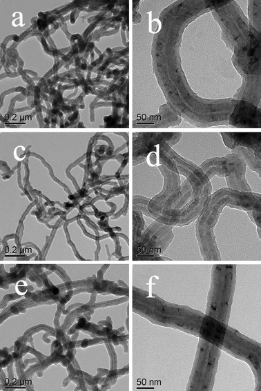 | ||
| Fig. 6 TEM images of core–shell PANI-MWNTs nanocomposites with the assistance of PCA (a, b), NSA (c, d) and BCA (e, f). | ||
The core–shell structured nanocomposites with PANI nano-layer coated uniformly on every MWNTs have several advantages for energy storage, as illustrated in Fig. 7. First, a PANI nano-shell with a thickness of about 20 nm greatly reduces the ion diffusion length and makes ions easily penetrate the PANI layer and reach the surface and inner of MWNTs during the charge–discharge process, realizing the efficient utilization of the electrode materials. Narrow diameters and optimized ionic diffusion path can reduce ionic diffuse resistance and charge transfer resistance, which greatly improve the specific capacitance of the electrode material.27 Second, the use of MWNTs without any oxidation treatment keeps its perfect graphitic lattice and unique electronic properties, which is in favor of charge transport and further makes nearly full use of the electrode materials. Third, the combination of the excellent mechanical properties of the MWNTs core with the PANI nano-shell can effectively overcome nanoparticle aggregation and release the cycle degradation problems or mechanical problems.28 Fourth, the use of MWNTs with high conductivity as support and active material can effectively reduce the power loss Ploss and energy loss Eloss due to IR loss at high charge–discharge current density (where I and R are charge–discharge current and resistance, respectively), which greatly enhances the specific capacitance.25 Thus, the MWNTs@PANI electrode presents high electrochemical capacitive performance.
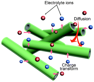 | ||
| Fig. 7 Schematic representation of the optimized ion diffusion path in MWNTs@PANI for energy storage. | ||
Conclusion
In summary, a uniformly structured nanocomposite with carbon nanotube as the core and polyaniline as the shell has been successfully prepared by the in situ polymerization of anilines on the walls of the nanotubes with the assistance of 1-pyrenesulfonic acid. The obtained nanocomposite shows higher specific capacitance due to a synergistic effect and a uniform core–shell structure, promising potential application as an electrode material of a supercapacitor for energy storage. The energy storage characteristics of the MWNTs@PANI nanocomposites as electrode materials are illustrated on the basis of the experimental results. This study also provides a new method to prepare a hybrid core–shell nanocomposite of carbon nanotubes and polyaniline by noncovalent interaction.Acknowledgements
This work was supported by NSFC (Grant No. 50821062, 21121001) and MOST (2009CB930400). We acknowledge Beijing Municipal Commission of Education for the special fund for the Disciplines & Postgraduate Education Construction project.References
- H. Guan, L. Z. Fan, H. C. Zhang and X. H. Qu, Electrochim. Acta, 2010, 56(2), 964 CrossRef CAS.
- L. L. Zhang, R. Zhou and X. S. Zhao, J. Mater. Chem., 2010, 20(29), 5983 RSC.
- J. W. Lang, L. B. Kong, W. J. Wu, Y. C. Luo and L. Kang, Chem. Commun., 2008, 4213 RSC.
- S. Q. Jiao, J. G. Tu, C. Y. Fan, J. G. Hou and D. J. Fray, J. Mater. Chem., 2011, 21(25), 9027 RSC.
- R. H. Baughman, A. A. Zakhidov and W. A. de Heer, Science, 2002, 297(5582), 787 CrossRef CAS.
- J. J. Xu, K. Wang, S. Z. Zu, B. H. Han and Z. X. Wei, ACS Nano, 2010, 4(9), 5019 CrossRef CAS.
- Y. Bardavid, J. Ghabboun, D. Porath, A. B. Kotylar and S. Yitzchaik, Polymer, 2008, 49(9), 2217 CrossRef CAS.
- J. Ge, G. H. Cheng and L. W. Chen, Nanoscale, 2011, 3(8), 3084 RSC.
- S. B. Yoon, E. H. Yoon and K. B. Kim, J. Power Sources, 2011, 196(24), 10791 CrossRef CAS.
- Z. Q. Niu, P. S. Luan, Q. Shao, H. B. Dong, J. Z. Li, J. Chen, D. Zhao, L. Cai, W. Y. Zhou, X. D. Chen and S. S. Xie, Energy Environ. Sci., 2012, 5(9), 8726 CAS.
- Y. Li, Y. Z. Fang, H. Liu, X. M. Wu and Y. Lu, Nanoscale, 2012, 4(9), 2867 RSC.
- F. Aviles, J. V. Cauich-Rodriguez, L. Moo-Tah, A. May-Pat and R. Vargas-Coronado, Carbon, 2009, 47(13), 2970 CrossRef CAS.
- T. M. Wu, Y. W. Lin and C. S. Liao, Carbon, 2005, 43(4), 734 CrossRef CAS.
- X. H. An, T. J. Simmons, R. Shah, C. Wolfe, K. M. Lewis, M. Washington, S. K. Nayak, S. Talapatra and S. Kar, Nano Lett., 2010, 10(11), 4295 CrossRef CAS.
- R. J. Chen, Y. G. Zhang, D. W. Wang and H. J. Dai, J. Am. Chem. Soc., 2001, 123(16), 3838 CrossRef CAS.
- Y. L. Zhao and J. F. Stoddart, Acc. Chem. Res., 2009, 42(1), 1161 CrossRef CAS.
- Q. Su, S. Pang, V. Alijani, C. Li, X. Feng and K. Müllen, Adv. Mater., 2009, 21(31), 3191 CrossRef CAS.
- H. Fan, H. Wang, N. Zhao, X. Zhang and J. Xu, J. Mater. Chem., 2012, 22(6), 2774 RSC.
- T. J. Simmons, J. Bult, D. P. Hashim, R. J. Linhardt and P. M. Ajayan, ACS Nano, 2009, 3(4), 865 CrossRef CAS.
- C. C. Hu and J. Y. Lin, Electrochim. Acta, 2002, 47(25), 4055 CrossRef CAS.
- Y. Zhou, Z. Y. Qin, L. Li, Y. Zhang, Y. L. Wei, L. F. Wang and M. F. Zhu, Electrochim. Acta, 2010, 55(12), 3904 CrossRef CAS.
- J. Yan, T. Wei, B. Shao, Z. J. Fan, W. Z. Qian, M. L. Zhang and F. Wei, Carbon, 2010, 48(2), 487 CrossRef CAS.
- Y. Q. Dou, Y. P. Zhai, H. J. Liu, Y. Y. Xia, B. Tu, D. Y. Zhao and X. X. Liu, J. Power Sources, 2011, 196(3), 1608 CrossRef CAS.
- H. Wang, Q. Hao, X. Yang, L. Lu and X. Wang, Nanoscale, 2010, 2(10), 2164 RSC.
- Y. G. Wang, H. Q. Li and Y. Y. Xia, Adv. Mater., 2006, 18(19), 2619 CrossRef CAS.
- P. Soudan, P. Lucas, H. A. Ho, D. Jobin, L. Breau and D. Belanger, J. Mater. Chem., 2001, 11(3), 773 RSC.
- K. Wang, J. Y. Huang and Z. X. Wei, J. Phys. Chem. C, 2010, 114(17), 8062 CAS.
- H. Zhang, G. P. Cao, Z. Y. Wang, Y. S. Yang, Z. J. Shi and Z. N. Gu, Electrochem. Commun., 2008, 10(7), 1056 CrossRef CAS.
| This journal is © The Royal Society of Chemistry 2012 |