Bionic system for countercurrent multi-stage micro-extraction
Shaowei
Li
*a,
Shan
Jing
a,
Qiang
Luo
a,
Jing
Chen
a and
Guangsheng
Luo
b
aInstitute of Nuclear and New Energy Technology, Tsinghua University, Beijing 100084, China. E-mail: lsw@tsinghua.edu.cn; Fax: (+8610)-62791740; Tel: (+8610)-80194037
bDepartment of Chemical Engineering, Tsinghua University, Beijing 100084, China
First published on 17th September 2012
Abstract
A bionic system, analogous to the human cardiovascular system, is developed to realize countercurrent, multi-stage micro-extraction. High mass transfer rates and high recovery efficiency were achieved. The system can be applied to any type of micro-extractor and may promote the application of micro-extraction in a wide variety of fields.
In the past decade, microfluidic devices have been the focus of numerous studies because of their high efficiency, safety, repeatability and facile controllability.1 Especially for liquid–liquid extraction, high speed and high performance can be achieved by the microextraction system, benefiting from its high specific interface area, large interface-to-volume ratio, and short diffusion distances.1–7 Although liquid–liquid extraction is an important operation unit in chemical processes that has been widely used in, for example, the petrochemical industry, nuclear reprocessing, and ore processing,8–14 conventional extraction systems, such as mixer-settlers, pulse columns, and centrifugal contactors, suffer from low efficiency, high energy consumption, and large equipment dimensions. Comparably, the microextractoin systems are more efficient: they can reach high extraction performance without any mechanical stirring, mixing, or shaking and can be integrated with other operation units in a small space. Owing to these advantages, microextraction has been used in the separation of metal ions,12,15 the detection of pesticide,16 the optical resolution of amino acids,17 the separation of steroids,13 the clean-up of alkaloids,14 and the separation of proteins.18
The feasibility of microextraction in chemical processes, however, is still limited by some other factors. The existing microextraction systems are mostly cocurrent operated. Though the mass transfer speed is much faster than that of the conventional extractors, the recovery efficiency of the cocurrent microextraction can reach no higher than that of a conventional device with a single theoretical separation stage. To increase recovery efficiency, countercurrent flow of two immiscible liquids to achieve multi-stage extraction is often used,19–22 but it is difficult to realize countercurrent flow at the micro-scale because viscosity and surface wetting dominate over gravity and inertial effects.23 Difficulty in achieving countercurrent two-phase flow has been a barrier to the application of micro-extraction in chemical processes. Some efforts to overcome this problem have been reported,24,25 but the methods used are mainly based on surface modification, in which the physical properties of the fluid and the operating conditions are limited to a narrow range to enable steady flow.26,27 A more robust countercurrent micro-flow system feasible for a wide range of materials and operation conditions is required. The human cardiovascular system, which transports blood to all parts of the body, provided us with the inspiration for such a system.
Fig. 1a shows the cardiovascular system. Blood flow is controlled by the heart's systole and diastole and the directional constraints of the mitral, aortic, tricuspid, pulmonary, and venous valves. Based on this flow control concept, a countercurrent micro-extraction system was developed. The system is mainly composed of two airtight syringes and four check valves, as shown in Fig. 1b. Reciprocation of the syringes substitutes for the heartbeat, while the four check valves control flow direction. Fluid circulates in the system when the syringe pistons move back and forth. Fig. 1c shows the detailed countercurrent micro-extraction system based on Fig. 1b. Instead of arterial and venous blood, organic (solvent) and aqueous (feed) solutions flow through the system by syringe reciprocation and valve constraints. Contact between the two fluids is achieved by introducing multi-stage micro-extractors, with stage numbers 1, 2, 3 ⋯ N. Each micro-extractor is composed of two check valves, a micro-contactor and a phase separator, as shown in Fig. 1d. Imitating the venous valve, which prevents backflow of venous blood, two check valves are placed at the organic and aqueous inlets to each stage of the micro-extractor, preventing back flow of the organic and aqueous liquids. When the syringe pistons move forward, the solvent in the right-hand side syringe is pushed into the micro-extractor. In the micro-extractor, the solvent passes through check valve A but is stopped by check valve B. Thus, all of the solvent flows into the micro-contactor, without backflow to the aqueous phase inlet, and is finally injected into the extract collection tank. Simultaneously, the raffinate in the left-hand side syringe is pushed into the raffinate collection tank. The syringe pistons then reverse their direction and the solvent is drawn from its tank into the right-hand syringe. Simultaneously, the aqueous feed is drawn out of the feed tank, into the micro-extractor. Similarly, all of the feed flows into the micro-contractor under the control of the check valves. The feed and the solvent then form a stable, segmented flow in the micro-channel of the contractor and the solute within the aqueous phase is extracted into the organic phase. Phase separation then takes place in the phase separator under the effect of surface wetting and the feed finally flows into the left-hand syringe. The extraction efficiency is greatly enhanced in the segmented flow because of the short mass transfer distances and inter-recirculation within the segmented fluid.2,4,28N-stage, countercurrent micro-extraction is carried out by reciprocal movement of the syringe pistons, and the total flow rate is determined by the stroke length and frequency. The flow ratio between the two phases can be regulated by changing the stroke lengths or the radii of the two syringes. The lengths of the fluid segments within the micro-contactor are determined by the strokes of the syringes and greatly influence extraction efficiency. In all situations, the two syringes must move synchronously.
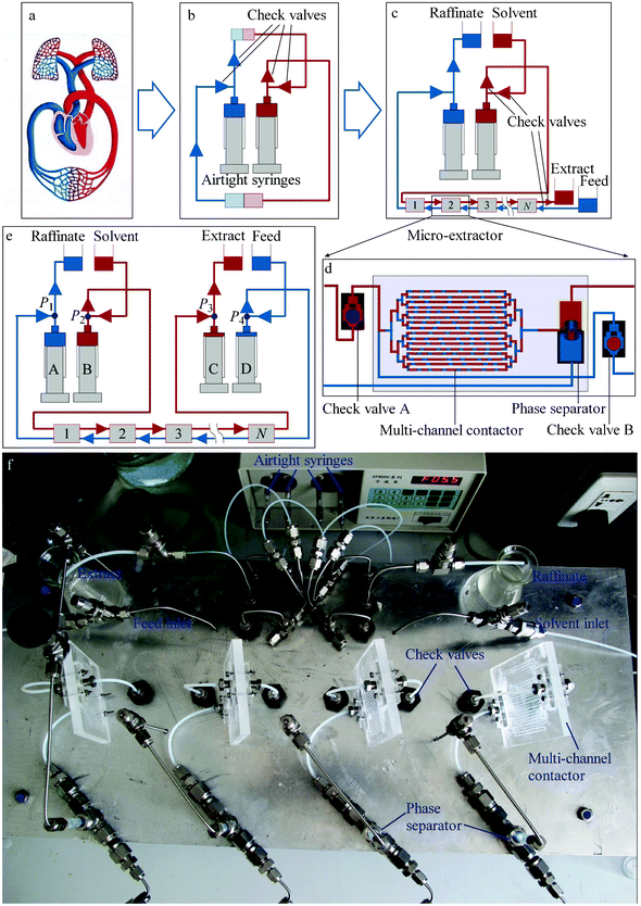 | ||
| Fig. 1 Derivation of the countercurrent micro-extraction system. (a) The human cardiovascular system. (b) A simulated cardiovascular system, with the heart replaced by airtight syringes and check valves. Reciprocal motion of the syringes substitutes for the heartbeat. (c) The asymmetrical countercurrent micro-extraction system, with systemic circulation replaced by multi-stage micro-extractors, performing mass transfer between the organic and aqueous solutions. (d) Configuration of one stage of the micro-extractor, including a micro-contactor, a phase separator and two check valves. (e) The symmetrical countercurrent micro-extraction system, with two further syringes for input of the feed and output of the extract. (f) The four-stage countercurrent micro-extraction setup arranged on a 20 × 50 cm panel. | ||
The system in Fig. 1c was modified to the symmetrical system shown in Fig. 1e, which is more robust. In this configuration, an additional pair of syringes is used for the output of the extract and the input of the feed. The additional pair of syringes moves in the opposite direction to the original pair, but the reciprocation frequencies of the two pairs are the same. The syringes are marked A, B, C, and D. The strokes and radii of syringes A and D (or B and C) are identical, to ensure equal inlet and outlet flow rates of the aqueous (or organic) phases. The four-stage countercurrent micro-extraction setup shown in Fig. 1e was built, as shown in Fig. 1f. The experimental setup was arranged on a 20 × 50 cm panel. The multi-channel contactor was fabricated on a 60 × 80 mm polymethyl methacrylate (PMMA) sample plate using an end mill. The channel dimensions were 0.5 × 0.5 × 60 mm (width × height × length). 16 parallel channels were placed on the plate with a spacing of 2 mm. The contactor was sealed using another PMMA thin plate (1 mm in thickness) by high-pressure thermal sealing techniques. The upper part of the phase separator was fabricated from Teflon® tube and the lower part from stainless steel tube. The check valve was fabricated by a stainless steel shell and ruby ball, with an inner structure shown in Fig. 1d.
Pressure balance is a key factor that determines the stability of the countercurrent micro-flow. The pressures marked as P1, P2, P3, and P4 in Fig. 1e are monitored by on-line pressure sensors. If P2 > P1, there will be an undesirable flow from the solvent tank to the raffinate tank through the first stage of the extractor. Therefore, P1 must remain higher than P2 throughout the cycle, which can be achieved by adjusting the heights of the solvent and the raffinate reservoirs. The same applies to P3 and P4. We identified the pressures as balanced if P1 > P2 and P3 > P4 throughout the process and in this situation, the countercurrent micro-flow was steady. That is to say, the period-average interface location in each phase separator did not visibly change. Two examples of the monitored pressures at steady state are shown in Fig. 2. The flow ratios of the organic to aqueous phases were 1![[thin space (1/6-em)]](https://www.rsc.org/images/entities/char_2009.gif) :1 and 5:1 in Fig. 2a and b, respectively. We can see that P2 remained below P1 over the whole cycle and P4 remained below P3, so the pressures are balanced. The flow of the organic phase is driven by the pressure difference between P2 and P3, i.e., ΔPo = P2 − P3 so that the organic phase flows from syringe B to syringe C through the extractors only under the condition ΔPo > 0. When ΔPo < 0, the check valves prevent reverse flow of the organic phase. The yellow area in Fig. 2 denotes the driving force for organic phase flow. Similarly, the flow of the aqueous phase is driven by the pressure difference ΔPa = P4 − P1, and the pink area in Fig. 2 denotes the driving force. The organic and aqueous phases flow alternately in each period. The yellow and pink areas in Fig. 2a are almost the same for the flow ratio of 1:1. In contrast, the yellow area is larger than the pink area in Fig. 2b, for which the flow ratio was 5:1. There is a monotonic relationship between the flow rate and the driving force area.
:1 and 5:1 in Fig. 2a and b, respectively. We can see that P2 remained below P1 over the whole cycle and P4 remained below P3, so the pressures are balanced. The flow of the organic phase is driven by the pressure difference between P2 and P3, i.e., ΔPo = P2 − P3 so that the organic phase flows from syringe B to syringe C through the extractors only under the condition ΔPo > 0. When ΔPo < 0, the check valves prevent reverse flow of the organic phase. The yellow area in Fig. 2 denotes the driving force for organic phase flow. Similarly, the flow of the aqueous phase is driven by the pressure difference ΔPa = P4 − P1, and the pink area in Fig. 2 denotes the driving force. The organic and aqueous phases flow alternately in each period. The yellow and pink areas in Fig. 2a are almost the same for the flow ratio of 1:1. In contrast, the yellow area is larger than the pink area in Fig. 2b, for which the flow ratio was 5:1. There is a monotonic relationship between the flow rate and the driving force area.
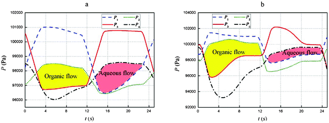 | ||
| Fig. 2 Pressure in the four syringes. (a) The flow ratio of the organic and aqueous phases was 1:1. (b) The flow ratio of the organic and aqueous phases was 5:1. The reciprocation frequency was 0.043 s−1, and the stroke of the aqueous phase syringes was 80 μL. The yellow area denotes the driving force of the organic flow, and the pink area denotes the driving force of the aqueous flow. | ||
The extraction performance of the setup shown in Fig. 1f was characterized by the extraction of Zr4+ from a HNO3–water solution to 30% tributyl phosphate (TBP)–kerosene. The HNO3–water/TBP–kerosene system is a widely-used system in nuclear reprocessing and ore processing. The aqueous feed was prepared by dissolving 1.2 g L−1 Zr(NO3)4 in 7.5 mol L−1 HNO3 solution. The solvent, 30% TBP–kerosene, was equilibrated with 7.5 mol L−1 HNO3 solution before extraction. The concentration of Zr(IV) was measured by inductively-coupled plasma–atomic absorption spectroscopy, and the extraction and recovery efficiencies were calculated from the measurements. Fig. 3a shows the extraction efficiency under various operating conditions. The extraction efficiency is defined as the ratio between the actual and theoretical extraction quantities. Over a wide range of flow rates (with reciprocation frequencies varying from 0.04 to 0.8 s−1), the extraction efficiency was no less than 95% at an organic to aqueous phase flow ratio of 1:1 and was no less than 90% at a flow ratio of 2:1. Reaching such a high extraction efficiency, the resident time was just several seconds. Comparatively, the resident time of a mixer-settler is tens of minutes to reach a similar efficiency. The relatively high extraction efficiency of our system is due to the short mass transfer distances and inter-recirculation within the segmented fluid, as we mentioned above. The Zr4+ recovery efficiency, which is defined as the percentage of the extracted quantity in the total quantity of Zr4+, is shown in Fig. 3b, comparing the single-stage extraction and four-stage countercurrent extraction. The recovery efficiency increased from 67.7 to 94.3% when the flow ratio (or phase ratio) was 1:1 and from 80.8 to 94.8% when the flow ratio (or phase ratio) was 2:1. Recovery efficiency was greatly increased when the multi-stage countercurrent extraction was carried out. This is the reason why multi-stage countercurrent extraction is required in real production. Higher recovery efficiencies can be further attained by increasing the number of stages.
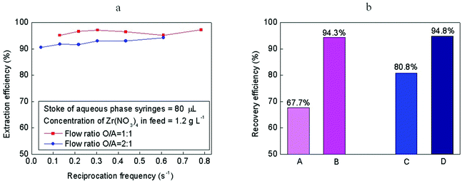 | ||
| Fig. 3 Extraction performance. (a) Extraction efficiency vs. reciprocation frequency. (b) Recovery efficiency comparison. A: Single-stage contact extraction, phase ratio = 1:1. B: Four-stage countercurrent micro-extraction, flow ratio = 1:1, reciprocation frequency = 0.6, stroke of aqueous phase syringes = 80 μL. C: Single-stage contact extraction, phase ratio = 2:1. D: Four-stage countercurrent micro-extraction, flow ratio = 2:1, reciprocation frequency = 0.6, stroke of aqueous phase syringes = 80 μL. | ||
Countercurrent extraction is an indispensable operation unit in chemical processes. We have developed a bionic system to achieve countercurrent operation during micro-extraction, with both high mass transfer efficiency and high recovery efficiency. Scale-up can be easily achieved by increasing the number of channels in the micro-contactor. The micro-contactor is not limited to the multi-channel configuration described in this work, thus enabling a wide range of variations. The approach described here overcomes a key problem to achieve a “factory on a table” and has many potential applications in a wide variety of chemical processes involving separation.
Acknowledgements
This work was supported by the National Natural Science Foundation of China (21106077) and Beijing Natural Science Foundation (2113047).References
- W. Ehrfeld, V. Hessel and H. Löwe, Microreactors: New Technology for Modern Chemistry. Wiley-VCH, Weinheim, 2000 Search PubMed.
- A. Günther and K. F. Jensen, Lab Chip, 2006, 6, 1487–1503 RSC.
- T. Thorsen, R. W. Roberts, F. H. Arnold and S. R. Quake, Phys. Rev. Lett., 2001, 86, 4163–4166 CrossRef CAS.
- J. R. Burns and C. Ramshaw, Lab Chip, 2001, 1, 10–15 RSC.
- K. K. R. Tetala, J. W. Swarts, B. Chen, A. E. M. Janssen and T. A. van Beek, Lab Chip, 2009, 9, 2085–2092 RSC.
- T. Maruyama, et al. , Analyst, 2004, 129, 1008–1013 RSC.
- P. Žnidaršič-Plazl and I. Plazl, Lab Chip, 2007, 7, 883–889 RSC.
- J. Korkisch, Nature, 1966, 210, 626–627 CrossRef CAS.
- H. A. C. Mckay and J. H. Miles, Nature, 1963, 199, 65–66 CrossRef CAS.
- J. M. Fletcher, Nature, 1963, 197, 957–958 CrossRef.
- J. Danon and A. A. L. Zamit, Nature, 1956, 177, 746–747 CrossRef CAS.
- J. B. Rosenbaum, Science, 1976, 191, 720–723 CAS.
- D. P. Neves and Y. Tavares, Science, 1955, 121, 313–314 CAS.
- H. M. Irving, F. J. C. Rossotti and J. G. Drysdale, Nature, 1952, 169, 619–620 CrossRef CAS.
- M. Tokeshi, T. Minagawa and T. Kitamori, Anal. Chem., 2000, 72, 1711–1714 CrossRef CAS.
- A. Smirnova, K. Mawatari, A. Hibara, M. A. Proskurnin and T. Kitamori, Anal. Chim. Acta, 2006, 558, 69–74 CrossRef CAS.
- T. Honda, M. Miyazaki, Y. Yamaguchi, H. Nakamura and H. Maeda, Lab Chip, 2007, 7, 366–372 RSC.
- Y. S. Huh, C.-M. Jeong, H. N. Chang, S. Y. Lee, W. H. Hong and T. J. Park, Biomicrofluidics, 2010, 4, 014103 CrossRef.
- Y. Ito and R. L. Bowman, Science, 1971, 173, 420–422 CAS.
- T. Tanimura, J. J. Pisano, Y. Ito and R. L. Bowman, Science, 1970, 169, 54–56 CAS.
- Y. Ito and R. L. Bowman, Science, 1970, 167, 281–283 CAS.
- P. P. Minieri and A. G. Mistretta, Science, 1955, 122, 1234–1234 CAS.
- J. Atencia and D. J. Beebe, Nature, 2005, 437, 648–655 CrossRef CAS.
- A. Hibara, et al. , Anal. Chem., 2002, 74, 1724–1728 CrossRef CAS.
- A. Aota, M. Nonaka, A. Hibara and T. Kitamori, Angew. Chem., Int. Ed., 2007, 46, 878–880 CrossRef CAS.
- A. Aota, A. Hibara and T. Kitamori, Anal. Chem., 2007, 79, 3919–3924 CrossRef CAS.
- K. L. Helton and P. Yager, Lab Chip, 2007, 7, 1581–1588 RSC.
- A. Günther, M. Jhunjhunwala, M. Thalmann, M. A. Schmidt and K. F. Jensen, Langmuir, 2005, 21, 1547–1555 CrossRef.
| This journal is © The Royal Society of Chemistry 2012 |