High color rendering white light-emitting diodes based on a green silicate phosphor mixed with a red dye-bridged hybrid
Seung-Yeon
Kwak
a,
Na
Ree Kim
a,
Jae
Hong Kim
b and
Byeong-Soo
Bae
*a
aLaboratory of Optical Materials and Coating (LOMC), Department of Materials Science and Engineering, Korea Advanced Institute of Science and Technology (KAIST), Daejeon 305-701, Republic of Korea. E-mail: bsbae@kaist.ac.kr; Fax: +82 42 350 3310; Tel: +82 42 350 4119
bDepartment of Chemical Engineering, Yeungnam University, Gyeongsan 712-749, Republic of Korea. E-mail: jaehkim@ynu.ac.kr; Fax: +82 53 810 4631; Tel: +82 53 810 2521
First published on 19th October 2012
Abstract
White light-emitting diodes (LEDs) using a wavelength converter composed of a red dye-bridged hybrid (DBH) mixed with a green silicate phosphor are fabricated. The red DBH is synthesized by chemically bonding epoxy functional oligosiloxane and red fluorescent dye for application in a red wavelength converter of white LEDs. To date, inorganic phosphors and quantum dots have been reported as red emitters. In this report, we suggest a dye based red wavelength converter for high color rendering white LEDs. The structural and optical properties of the DBH are evaluated. The fabricated white LEDs have a high color rendering index up to 90. They show facile color temperature tunability, a broad color gamut, and sufficient efficacy of 33.3 lm W−1 for applications in lighting technology. Also, both forward-bias current stability and long-term thermal stability are achieved for solid-state lighting applications.
Introduction
Solid-state lighting has the potential to reduce energy consumption and provide eco-friendly illuminations and displays. Among many solid-state lighting technologies, light-emitting diodes (LEDs) are dominant devices in both lighting research and market share, on the basis of their energy efficiency, reliability, environmentally friendly characteristics, and wide application range. The most common method to produce white light is by combining a blue LED with a yellow wavelength converter such as Y3Al5O12:Ce3+ (YAG:Ce).1 Although this is an efficient and cost-effective method, it provides a poor color rendering index (CRI) and insufficient color temperature for use in room lighting and displays. Recently, this type of di-chromatic (yellow-blue) white LED has been evolved to a tri-chromatic white LED using a blue LED incorporating green and red phosphors2–4 to achieve a high CRI and color tuning. However, it is difficult to find an adequate red inorganic phosphor for tri-chromatic white LEDs, because common red inorganic phosphors have disadvantages related to absorption, stability, and cost. The research on red phosphors for white LEDs has focused on oxide and sulfide based phosphors.5–7 However, most oxide-based phosphors suffer high thermal quenching at elevated temperatures.8 Sulfide red phosphors are moisture sensitive and they show fluorescence saturation when the blue emission from LED becomes intense by increasing forward-bias current.9 Nitride phosphors have attracted interest for their high stability as a red phosphor, but they are expensive due to the demanding synthesis conditions such as high temperature and high nitrogen pressure, which limit the synthesis method.10,11 Thus, the problem of obtaining a sufficiently high CRI has limited the use of inorganic phosphors.Recently, quantum dots (QDs) have been explored as a potential fluorescent material on the basis of their color tunability, narrow emission, and high luminescence efficiency.12–14 It was reported that incorporating red CdSe QDs with a green inorganic phosphor increases the CRI of a white LED up to 90.1.15 It was also reported that silica-coated InP/ZnS QDs together with a green phosphor and YAG showed a CRI value as high as 86.16 However, QDs are hazardous and expensive due to their difficult synthesis method, and their long-term stability has not been verified.
Organic dyes are inexpensive and can be used as an alternate fluorescent material in LEDs. The broad absorption band of these dyes allows for high efficiency and it is easy to modify their molecular structure to generate red fluorescence. However, they have poor stability as they can be degraded by oxygen, moisture, heat, and external light. Recently, we reported on a dye-bridged hybrid (DBH), a one-body system of a dye and matrix consisting of a sol–gel derived nano-sized oligosiloxane employed to overcome the poor stability of the dye.17–19 In a DBH, dyes are chemically bridged to oligosiloxane, and thereby the dyes are seized and caged in the dense siloxane network, leading to more stable characteristics. Molecular stacking of the dye molecules is prevented by the covalently bridged structure, and the concentration stability is thus enhanced and the dye is homogeneously dispersed in the matrix. We demonstrated that the photoluminescence characteristics were not degraded under 120 °C heat during hundreds of hours. Also, the photoluminescence intensity of the DBH is less sensitive to temperature, and thus its initial characteristics are preserved upon elevated temperature, since the internal molecular rotation is restricted by the chemical structure.
In this study, a red fluorescent DBH is synthesized using an epoxy functional oligosiloxane and red fluorescent dye for a red wavelength converter of a white LED. Scheme 1 presents the schematic procedure to synthesize a dye-bridged oligosiloxane (DBO) resin by a sol–gel process and a DBH by curing a DBO resin. First, the red dye is covalently bridged with alkoxysilane, forming an epoxy functional oligosiloxane, via a sol–gel process. Finally, this DBO resin becomes a solid-state DBH through epoxy curing. We have fabricated white LEDs using the DBH and a green silicate phosphor mixture and the characteristics of white LEDs are investigated. Exhibiting a high color rendering index of up to 90 and stability under forward-bias current and thermal stress, these LEDs offer potential as a solid-state lighting source.
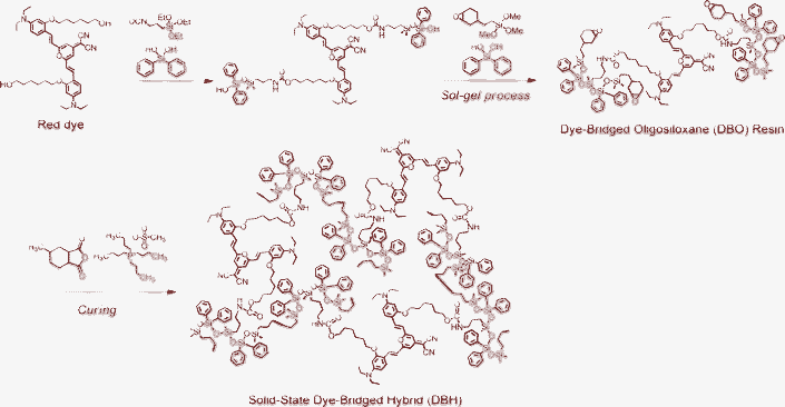 | ||
| Scheme 1 Fabrication scheme of dye-bridged oligosiloxane (DBO) resin by a sol–gel process and dye-bridged hybrid (DBH) by curing of DBO. | ||
Experimental
Synthesis of dye-bridged oligosiloxane (DBO) resin
The red dye derivative of 4-(dicyanomethylene)-2-methyl-6-(4-dimethylaminostyryl)-4H-pyran (DCM) was synthesized using 4-diethylamino-2-(6-hydroxy-hexyloxy)-benzaldehyde, (2,6-dimethyl-4H-pyran-4-ylidene)malononitrile. We followed the same synthesis procedure as reported in ref. 17 for red dye. Synthesized red dye (0.656 mmol) and 3-(triethoxysilyl)propyl isocyanate (1.968 mmol) were mixed and reacted at 80 °C for 6 h. 1.968 mmol of diphenylsilanediol powder and 0.56 mmol of barium hydroxide monohydrate were added to the solution in the presence of 5 mL of chloroform. The mixture was reacted at 80 °C for 2 h. Then [2-(3,4-epoxycyclohexyl)ethyl] trimethoxysilane (0.708 mol) and diphenylsilanediol (0.706 mol) were added to the mixture to initiate a condensation reaction via a non-hydrolytic sol–gel process. The diphenylsilanediol was gradually added during 30 min to prevent self-condensation. The reaction was allowed to proceed for 4 h at 80 °C and barium hydroxide monohydrate (6.56 mmol) was used as a catalyst. During the reaction, nitrogen was purged to blow out alcohol, a by-product of the sol–gel process. Finally, we obtained a red DBO resin. The concentration of red dye in the DBO resin was 2 mmol L−1 and other DBOs with different concentrations were synthesized by the same method.Characterization of DBO resin and DBH
A 600 MHz NMR spectrometer (DMX 600, Bruker) was used for a 29Si NMR analysis. DBO resin was dissolved in chloroform-d with chromium(III) acetylacetonate as a relaxation agent of silicon for the measurement. The molecular weight distribution of the DBO resin was analyzed using a matrix-assisted laser desorption and ionization time-of-flight mass spectrometry (MALDI-TOF MS) analyzer (Voyager DE-STR, Applied Biosystems). For mass spectrometry measurement, we used 2,5-dihydroxybenzoic acid and acetone as a matrix and a solvent of the DBO resin, respectively. Fourier transform infrared (FT-IR) spectra were measured to obtain the conversion degree of the DBO resin using a FT-IR spectrometer (FT/IR-680 Plus, Jasco). The scanning resolution was 4 cm−1 in a wavenumber range 650–4000 cm−1. For the 13C NMR analysis, the DBO resin was dissolved in chloroform-d with 30 vol% and chromium(III) acetylacetonate with a concentration of 30 mg L−1 was added with and the resultant solution was analyzed by a FT 500 MHz NMR spectrometer (AMX500, Bruker). The cured DBH was ground to a powder and analyzed with a 400 MHz solid-state 13C NMR (Avance 400WB, Bruker) using the cross polarization-magic angle spinning (CP-MAS) method. The refractive index of the DBH was measured using a prism coupler (Model 2010/M, Metricon) at 632.8 nm. Absorption and emission spectra of the DBH were measured using an ultraviolet-visible (UV/Vis) spectra analyzer (UV-3101 PC Spectrophotometer, Shimadzu) and photoluminescence spectroscopy (DARSA PRO 5100 PL System, PSI trading Co., Ltd) at room temperature using a xenon lamp as an excitation source.Fabrication and characterization of white LED
Red DBO resin and green phosphor are combined to be used as a wavelength converter for a white LED. For the green phosphor, we used a silicate phosphor (EG2762™, Intematix) consisting of Eu doped silicate, the main emission peak of which is at 525 nm. It is known that silicate phosphor has high efficiency but is sensitive to temperature and moisture. To make a white LED, the green phosphor was homogeneously dispersed in a DBO resin using a magnetic stirrer. For thermal curing, hexahydro-4-methylphthalic anhydride and tetrabutylphosphonium methanesulfonate were used as a hardener and initiator, respectively. The DBO resin and green phosphor mixture were dispensed on top of bare blue LED chips and thermally cured at 150 °C for 2 h. Characterization of the encapsulated white LED on the basis of electroluminescence spectra, color temperature, CRI, and color coordinates was carried out using a photoluminescence spectroscope (DARSA PRO 5100 PL System, PSI trading Co., Ltd) and integrating sphere under forward bias current of 20 mA at room temperature.Results and discussion
Characteristics of DBO resin and DBH
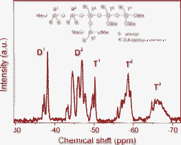
29Si NMR spectroscopy was conducted to characterize the oligosiloxane formation and to confirm the existence of unreacted precursors in the red DBO resin (Fig. 1). Dimeric species (Dn) originate from diphenylsilanediol, which has two siloxane bonding sites, and trimeric species (Tn) is originated from [2-(3,4-epoxycyclohexyl)ethyl]trimethoxysilane, which have a maximum of three siloxane bonds during the sol–gel reaction. The superscript ‘n’ represents the number of oxygen molecules bridged to a Si atom. In the DBO resin, D0 and T0 species are not observed at −34 ppm and −41 ppm, respectively, indicating that there is no unreacted monomeric precursor and the entire precursor participated in the formation of the siloxane network. The area ratio of Dn/Tn is 1.01, because the molar ratio of dimeric species and trimeric species is one to one in DBO resin. The peak area of D2 (−42 to −47 ppm) is larger than that of D1 (−36 to −38 ppm) and the area of T2 (−57 to −61 ppm) and T3 (−65 to −69 ppm) is dominant over T1 (−49 to −51 ppm), indicating abundant formation of siloxane bonds. The condensation degree of the DBO resin, calculated by eqn (1) using the peak area of 29Si NMR, is 82%. | (1) |
We examined the MALDI-TOF MS of the DBO resin to analyze the molecular weight distribution of oligosiloxane, which falls in the range of 630–3000 m/z. The calculated molecular weight and experimental molecular weight of each peak are summarized in Table 1, where it is seen that each peak position of the practical molecular weight matches that of the calculated molecular weight. Through a comparison of the two peaks, we confirmed that the oligosiloxane of the DBO resin has a well-defined structure with oligomer size.
| Calculated (m/z) | Practical (m/z) | |
|---|---|---|
| Trimer | 640–648 | 629–661 |
| Tetramer | 840–850 | 827–851 |
| Pentamer | 1038–1050 | 1013–1055 |
| Hexamer | 1236–1250 | 1211–1255 |
| Heptamer | 1434–1450 | 1404–1453 |
| Octamer | 1632–1650 | 1600–1652 |
The DBH is cured through epoxy polymerization with an anhydride hardener under quaternary phosphonium salts.20 The cured DBH was examined by FT-IR and 13C NMR to determine if it is fully cured. If the DBH was not fully polymerized, DBH would be degraded during thermal aging due to the existence of unreacted organic species and would show unreliable performance. Fig. 2 presents FT-IR spectra analysis results of the DBO resin and the cured DBH. A broad absorption spectrum of siloxane stretching is observed between 1130 cm−1 and 1020 cm−1 in the FT-IR spectra. Vibration of the epoxy group appears at 883 cm−1 and a C![[double bond, length as m-dash]](https://www.rsc.org/images/entities/char_e001.gif) C band of phenyl groups originating from diphenylsilanediol is observed at 1592 cm−1. As the thermal curing proceeds, the band of the epoxy group decreases but the amount of phenyl groups remains uniform in the matrix. Thus, the conversion degree of epoxy, which represents how much epoxy participates in the polymerization, can be calculated by comparing the area of epoxy groups and phenyl groups before and after thermal curing. The conversion degree of epoxy calculated using eqn (2) is 97%.
C band of phenyl groups originating from diphenylsilanediol is observed at 1592 cm−1. As the thermal curing proceeds, the band of the epoxy group decreases but the amount of phenyl groups remains uniform in the matrix. Thus, the conversion degree of epoxy, which represents how much epoxy participates in the polymerization, can be calculated by comparing the area of epoxy groups and phenyl groups before and after thermal curing. The conversion degree of epoxy calculated using eqn (2) is 97%.
 | (2) |
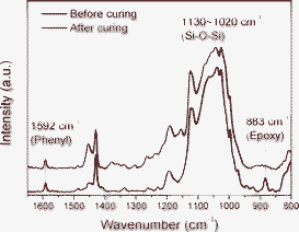 | ||
| Fig. 2 FT-IR spectra of before and after curing of DBO resin. | ||
13C NMR of the DBO resin and solid-state 13C NMR of DBH were measured to verify epoxy ring opening during the curing to form DBH. Fig. 3 shows 13C NMR analysis results of the DBO resin and DBH. Before curing, carbon beside the oxygen of cycloaliphatic epoxy (1a, 2a) is detected at 51–53 ppm in the 13C NMR spectra. For the solid-state 13C NMR, the carbon of cycloaliphatic epoxy at 51–53 ppm is chemically shifted to 60–80 ppm (1b, 2b), since the epoxy ring is opened during the polymerization. These results indicate that the DBO resin is cured, leading to the realization of the DBH.
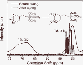 | ||
| Fig. 3 13C NMR and solid-state 13C NMR spectra of before and after curing of DBO resin. (Inset molecular structure represents ring opening of epoxy). | ||
The refractive index is an important factor for high efficiency white LEDs, because a high refractive index encapsulant allows light to be efficiently extracted from the LED. The refractive index of the DBH is measured by a prism coupler at a wavelength of 632.8 nm. The measured value is as high as 1.536 due to the presence of the phenyl group with high electronic polarizability.
Characteristics of DBH/silicate phosphor encapsulated white LEDs
DBO resin mixed with a green silicate phosphor is used as wavelength converter for a white LED. The main emission of the DBO resin with dye concentration of 1 mmol L−1 is 662 nm and the full width at half maximum (FWHM) is 98 nm. As the dye concentration decreases, the main emission is blue shifted so that it has a main peak at 644 nm and 632 nm when the dye concentration is 0.1 mmol L−1 and 0.05 mmol L−1, respectively. The first main absorption peak is at 496 nm and the second peak is at 378 nm, extending broadly in the spectrum range of 320 nm to 600 nm. The green phosphor of Eu2+ doped silicate has a main emission peak at 525 nm and its FWHM is 70 nm. The absorption spectrum range is 200 nm to 490 nm, which matches the emission of a blue LED chip at 450 nm. And the quantum yield of red DBO resin and green silicate phosphor are 80 and 88, respectively. The mixture was encapsulated on top of a bare blue LED package which has luminous efficacy of 9.2 lm W−1 and thermally cured at 150 °C for 2 h using hexahydro-4-methylphthalic anhydride and tetrabutylphosphonium methanesulfonate. The DBH/silicate phosphor encapsulated white LED has a large color gamut, because each primary color has distinguished color. RGB color coordinates of DBH, silicate phosphor, and blue LED chip on Commission Internationale de l'Eclairage (CIE) 1931 color space are (0.7052, 0.2921), (0.2750, 0.6224), and (0.1552, 0.0221), respectively. The area of the RGB color space covers 132.9% of the sRGB color space, which is the most common RGB color space used on monitors and HDTVs. The color coordinates of sRGB are (0.64, 0.33), (0.30, 0.60), and (0.15, 0.06), respectively. Thus, the white LED can express wider color space for use in display applications.The dye concentration and the quantity of silicate phosphor in the resin mixture are controlled to optimize the white color of the encapsulated LED. The concentration of the red dye in the DBO resin is controlled from 0.01 mmol L−1 to 2 mmol L−1. It shows yellow emission when 10 wt% of silicate phosphor is dispersed in the DBO resin and the dye concentration is between 0.02 mmol L−1 and 0.1 mmol L−1. The color coordinates (x, y) on CIE 1931 color space are (0.3905, 0.5443), (0.4547, 0.5033), and (0.5167, 0.4483) for dye concentration of 0.02 mmol L−1, 0.05 mmol L−1, and 0.1 mmol L−1, respectively. The tri-chromatic white LEDs show various white emissions depending on the dye concentration in the DBO resin. Characteristics of the DBH/silicate phosphor encapsulated white LEDs such as color coordinates, CRI, and color temperature depending on the dye concentration are listed in Table 2. Their color space coordinates and the electroluminescence (EL) spectra are presented in Fig. 4. The DBH/silicate phosphor mixture provides advantages in controlling color temperature and CRI by varying the dye concentration in the DBH. It is known that color temperature over 5000 K is cool white and less than 4000 K is warm white. Color temperature can be easily turned from cool white to warm white in the white LED for many lighting applications.
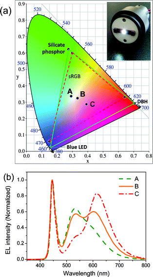 | ||
| Fig. 4 (a) Commission Internationale de l'Eclairage (CIE) color coordinates of the DBH/silicate phosphor encapsulated white LEDs. The dashed triangle is the color gamut of sRGB color space and the solid triangle represents the color gamut of DBH/silicate phosphor encapsulated white LED. (b) EL spectra of various DBH/silicate phosphor encapsulated white LEDs. | ||
| Point | Dye concentration (mmol L−1) | CIE x | CIE y | Ra | TC (K) | Luminous efficacy (lm W−1) |
|---|---|---|---|---|---|---|
| A | 0.02 | 0.2921 | 0.336 | 75 | 7637 | 43.4 |
| B | 0.05 | 0.3341 | 0.3237 | 90 | 5410 | 33.3 |
| C | 0.1 | 0.3917 | 0.2877 | 82 | 2689 | 23.1 |
DBH has main emission at 635 nm when its dye concentration is 0.05 mmol L−1. After red DBH is mixed with green silicate phosphor, a main red emission peak is seen around 610 nm. We consider that this is because of the energy transfer occurring from green silicate phosphor to red dye when their distance is near enough. In other words, the main emission around 610 nm is an overlapped state of green silicate and red DBH in which energy transfer occurs. Interestingly, if we fabricate a white LED with layer-by-layer structure (blue LED/green phosphor/0.05 mmol L−1 red DBH), the white LED has red emission around 635 nm, which is the emission of 0.05 mmol L−1 DBH. That is, it shows their own emissions if energy transfer does not occur by splitting red and green emitters.
When the dye concentration is 0.05 mmol L−1 (point B, Fig. 4), the DBH/silicate phosphor encapsulated white LED has ideal properties of a white point at (0.3341, 0.3237) and a very high CRI up to 90. The general CRI (Ra) is the average of eight components and is related to the color difference between the test colors and original test color samples.21 We fabricated a YAG:Ce phosphor encapsulated white LED using the same blue LED package and epoxy functional oligosiloxane to compare color rendering with DBH/silicate phosphor encapsulated white LED. The amount of YAG:Ce in the white LED was controlled to have similar color coordinates of DBH/silicate phosphor white LED at (0.33, 0.3461). The CRI values of the DBH/silicate phosphor encapsulated white LED and a YAG:Ce phosphor white LED depending on the eight color components were compared (Fig. 5). CRI of the YAG:Ce phosphor white LED which has a di-chromatic source of 73. As presented in Fig. 5, color rendering at 7.5R and 10P, which represent light greyish red and light reddish purple has increased by 26 and 29 points, respectively. These results indicate that the red emission of the DBH/silicate phosphor encapsulated white LED is stronger than that of the YAG:Ce phosphor based white LED. Also color rendering at 2.5G and 10BG which are related to green emission, are increased by 18 and 26 points due to the green silicate phosphor.
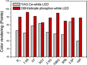 | ||
| Fig. 5 Color rendering index comparison of YAG:Ce encapsulated white LED and DBH/silicate phosphor encapsulated white LED (point B). | ||
The measured luminous efficacy of the DBH/silicate phosphor encapsulated white LED is between 23.1 and 43.4 lm W−1 using blue LED package with luminous efficacy of 9.2 lm W−1 at 20 mA. It was reported that the luminous efficacy of tri-chromatic white LEDs lies between 17–35 lm W−1 and luminous efficacy of tri-chromatic (green α-sialon:Yb2+ and red Sr2Si5N8:Eu2+) white LEDs was between 17–23 lm W−1.11 Another study on a green SrSi2O2N2:Eu and red CaSiN2:Ce based white LED showed luminous efficacy of 30 lm W−1.22 A white LED using CdSe red quantum dots with a green Sr3SiO5:Ce3+, Li+ showed efficiency of 14.0 lm W−1.15 The luminous efficacy of a green and red CdSe–ZnSe based white LED was 7.2 lm W−1.23 Thus, the present DBH/silicate phosphor encapsulated white LED has sufficient luminous efficacy compared to other reported tri-chromatic white LEDs.
The operation current has been increased from 20 mA to 80 mA at an interval of 20 mA to ensure stability under forward-bias current (Fig. 6). The number of photons emitted from the blue LED increases as the forward-bias current increases. If the red dye and silicate phosphor are not capable of accepting photons, the fluorescence intensity will be saturated. As seen in Fig. 6, the EL spectra show that the fluorescent intensity of the DBH and silicate phosphor is not saturated at high bias current. When the DBH/silicate phosphor encapsulated white LED is operated at 20 mA, it has color coordinates of (0.3341, 0.3237) and Ra is 90. After the forward current is increased to 80 mA, the white LED shows a CRI of 89 and the color coordinate is changed to (0.3395, 0.3303) that the changing range is (0.0054, 0.0066). The color temperature is changed from 5410 K to 5158 K. In a study by Jang et al., the color coordinates of a Sr3SiO5:Ce3+, Li+ and CdSe quantum dot based white LED varied from (0.2904, 0.2900) to (0.2914, 0.3017) and the CRI was changed from 90.1 to 88.9 when the forward-bias current was increased from 20 mA to 70 mA.15 With an increase of current from 10 mA to 60 mA, the color coordinates of a Tb3Al5O12:Ce3+ (TAG:Ce) based white LED varied from (0.3449, 0.3478) to (0.3408, 0.3349). In addition, a YAG:Ce based white LED showed color coordinate variation of (0.2923, 0.3281) to (0.2903, 0.3171) under the same conditions.24 It was reported that the fluorescent intensity of a red phosphor composed of Ca1−xSrxS:Eu2+ was saturated at current over 30 mA and a phosphor based white LED showed a decrease of Ra (92 → 88) and large variation of color coordinates.9 We can thus conclude that the present wavelength converter composed of a DBH and silicate phosphor has low photo-saturation and similar or higher stability under forward-bias current compared to quantum dot and inorganic phosphor based converters.
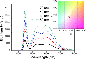 | ||
| Fig. 6 EL spectra and color coordinate shift of DBH/silicate phosphor encapsulated white LED under various forward-bias current. | ||
The DBH/silicate phosphor encapsulated white LED was thermally aged at 120 °C in an air atmosphere for 800 h to confirm its thermal stability. Fig. 7 shows EL spectra of the fabricated white LED before and after thermal aging. The EL spectrum of the white LED was largely maintained over 800 h. If they are expressed as color coordinates, the initial point was (0.3619, 0.3351) and it shifted to (0.3595, 0.3338) after 800 h aging. The change of color coordinates is at the third decimal place, which could be within a reasonable error range. Dye molecules are chemically bonded to the robust siloxane structure and internal molecular rotation is restricted, thereby preventing thermal decomposition. Furthermore, the silicate phosphor is protected by the dense siloxane network, which has low gas permeability25 from moisture, leading to more stable characteristics. These results indicate that the DBH/silicate phosphor encapsulated white LED can properly operate at elevated temperature.
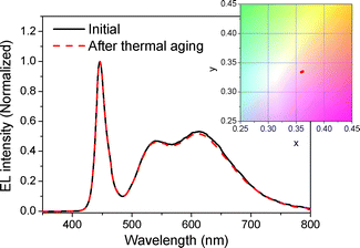 | ||
| Fig. 7 EL spectra and color coordinate shift of DBH/silicate phosphor encapsulated white LED before and after thermal aging at 120 °C for 800 h. | ||
Conclusions
A red dye-bridged hybrid (DBH) has been synthesized via a non-hydrolytic sol–gel reaction and combined with a silicate phosphor to use as a wavelength converter of white LEDs. Oligosiloxane formation of a fluorescent oligosiloxane and the curing behavior were investigated. We fabricated various white LEDs applying DBH and silicate phosphor on a blue LED. The fabricated DBH/silicate phosphor encapsulated white LED has a high CRI of up to 90 and shows large color temperature exchange from cool white to warm white depending on the dye concentration. It has a broad color gamut that it covers all of sRGB color space. The measured luminous efficacy is 33.3 lm W−1 at 20 mA. It has high stability under forward-bias current that the white emission is not that changed when the forward-bias current is increased from 20 mA to 80 mA. It also shows high thermal stability at 120 °C for 800 h. These characteristics indicate that the red DBH mixed with silicate phosphor has strong potential as a wavelength converter for high color rendering white LEDs.Acknowledgements
This work was supported by the National Research Foundation of Korea (NRF) grant funded by the Korea government (MEST) (No. 2012-0004992), and by grant No.EEWS-2012-N01110026 from EEWS Research Project of the office of KAIST EEWS initiative.References
- S. Nakamura, Proc. SPIE–Int. Soc. Opt. Eng., 1997, 3002, 26 CAS.
- R. Mueller-Mach, G. O. Mueller, M. R. Krames, H. A. Höppe, F. Stadler, W. Schnick, T. Juestel and P. Schmidt, Phys. Status Solidi A, 2005, 202, 1727 CrossRef CAS.
- R. Mueller-Mach, G. O. Mueller, M. R. Krames and T. Trottier, IEEE J. Sel. Top. Quantum Electron., 2002, 8, 339 CrossRef CAS.
- K. Sakuma, N. Hirosaki, N. Kimura, M. Ohashi, Y. Yamamoto, R.-J. Xie, T. Suehiro, K. Asano and D. Tanaka, IEICE Trans. Electron., 2005, E88–C, 2057 Search PubMed.
- S. Neeraj, N. Kijima and A. K. Cheetham, Chem. Phys. Lett., 2004, 387, 2 CrossRef CAS.
- D. Jia and D. N. Hunter, J. Appl. Phys., 2006, 100, 113125 Search PubMed.
- R.-J. Xie and N. Hirosaki, Sci. Technol. Adv. Mater., 2007, 8, 588 CrossRef CAS.
- A. A. Setlur, Electrochem. Soc. Interface, 2009, 18, 32 Search PubMed.
- H. Wu, X. Zhang, C. Guo, J. Xu, M. Wu and Q. Su, IEEE Photonics Technol. Lett., 2005, 17, 1160 CrossRef CAS.
- R.-J. Xie, N. Hirosaki, M. Mitomo, K. Sakuma and N. Kiumra, Appl. Phys. Lett., 2006, 89, 241103 CrossRef.
- R.-J. Xie, N. Hirosaki, N. Kimura, K. Sakuma and M. Mitomo, Appl. Phys. Lett., 2007, 90, 191101 CrossRef.
- M. J. Bruchez, M. Moronne, P. Gin, S. Weiss and A. P. Alivisatos, Science, 1998, 281, 2013 CrossRef CAS.
- B. O. Dabbousi, J. Rodríguez-Viejo, F. V. Mikulec, J. R. Heine, H. Mattoussi, R. Ober, K. F. Jensen and M. G. Bawendi, J. Phys. Chem. B, 1997, 101, 9463 CrossRef CAS.
- L. Li, T. J. Daou, I. Texier, T. T. Kim Chi, N. Q. Liem and P. Reiss, Chem. Mater., 2009, 21, 2422 CrossRef CAS.
- H. S. Jang, H. Yang, S. W. Kim, J. Y. Han, S.-G. Lee and D. Y. Jeon, Adv. Mater., 2008, 20, 2696 CrossRef CAS.
- J. Ziegler, S. Xu, E. Kucur, F. Meister, M. Batenschuk, F. Gindele and T. Nann, Adv. Mater., 2008, 20, 4068 CrossRef CAS.
- S. Y. Kwak, S. C. Yang, N. R. Kim, J. H. Kim and B. S. Bae, Adv. Mater., 2011, 23, 5767 CrossRef CAS.
- S. Y. Kwak, N. R. Kim, K. Lee, J. Yi, J. H. Kim and B. S. Bae, J. Sol-Gel Sci. Technol., 2011, 60, 137 Search PubMed.
- S. Y. Kwak, S. C. Yang, N. R. Kim, J. H. Kim and B. S. Bae, J. Sol-Gel Sci. Technol., 2012 DOI:10.1007/s10971-012-2676-z.
- B. Ellis, in Chemistry and Technology of Epoxy Resins, Blackie Academic, London, 1993 Search PubMed.
- CIE, in Method of Measuring and Specifying Color Rendering Properties of Light Sources, CIE publication, Vienna, Austria, 1995 Search PubMed.
- C.-C. Yang, C.-M. Lin, Y.-J. Chen, Y.-T. Wu, S.-R. Chuang, R.-S. Liu and S.-F. Hu, Appl. Phys. Lett., 2007, 90, 123503 CrossRef.
- H. Chen, C. Hsu and H. Hong, IEEE Photonics Technol. Lett., 2006, 18, 193 CrossRef CAS.
- H. S. Jang, Y.-H. Won and D. Y. Jeon, Appl. Phys. B: Lasers Opt., 2009, 95, 715 CrossRef CAS.
- K. H. Jung, J. Y. Bae, S. J. Park, S. Yoo and B. S. Bae, J. Mater. Chem., 2011, 21, 1977 RSC.
| This journal is © The Royal Society of Chemistry 2012 |

