Singlet oxygen photogeneration and 2,4,6-TCP photodegradation at Pt/TiO2 under visible light illumination†
Xuefeng
Hu
*a,
Huanhuan
Ji
ab and
Lei
Wu
ab
aKey Laboratory of Coastal Zone Environmental Processes, Yantai Institute of Coastal Zone Research, Chinese Academy of Sciences, Yantai Shandong 264003, P. R. China. E-mail: xfhu@yic.ac.cn; Fax: +86-535-2109000; Tel: +86-535-2109157
bUniversity of Chinese Academy of Sciences, Beijing 100049, PR China
First published on 22nd October 2012
Abstract
Pure and Pt nanoparticle-modified rutile TiO2 were synthesized via hydrolysis of TiCl4 in the absence or presence of Pt nanoparticles. HRTEM, XRD, and SEM were used to characterize the structure of the prepared catalysts. The resulting modified TiO2 catalysts show extended visible light absorbance. Photodegradation of 2,4,6-trichlorophenol (2,4,6-TCP) over these photocatalysts was investigated under visible light illumination. The Pt nanoparticles facilitate the separation of photogenerated electron–hole pairs at low Pt content, then enhances the photodegradation rate of 2,4,6-TCP. 0.18Pt–TiO2 achieved the best photocatalytic activity among the tested catalysts. It was found that singlet oxygen rather than ˙OH acts as the main oxidative species for the degradation of 2,4,6-TCP according to the experimental results. The degradation intermediates of 2,4,6-TCP were identified and the degradation pathway was proposed. Pt nanoparticles on TiO2 significantly enhance O2 adsorption and the formation of ˙O2−. The rutile surface is a favorable condition for stabilizing ˙O2−. These properties of the Pt nanoparticle-modified rutile TiO2 facilitate the formation of 1O2via the reaction of superoxide anions with holes.
Introduction
Many nanomaterials are able to sensitize the formation of singlet oxygen (1O2) upon photoexcitation.1 Photogeneration of 1O2 is known to play important roles in the photooxidation of organic compounds and the photodynamic therapy treatment of cancer. 1O2 photogeneration at a TiO2 surface under UV light illumination has been reported.2 However, the TiO2 photocatalytic degradation of organic pollutants proceeds mainly from the exertions of ˙OH produced by the oxidation of water and ˙O2− produced by the reduction of oxygen in air.3,4 The roles of 1O2 were often ignored in the TiO2 catalyzed organic pollutants photodegradation although 1O2 has been reviewed as a strong oxidizing reagent for organic pollutant degradation.5,6 The photodegradation of organic pollutants via the 1O2 mechanism conventionally requires organic photosensitizers.7,8 However, these organic photosensitizers are prone to photodegradation under photoillumination, which reduces the efficiency of the 1O2 generation.7–9 Janczyk et al. reported the surface modification of TiO2 with F− and silyl groups leading to the photodegradation of cyanuric acid.101O2 was thought to be responsible for the first steps of cyanuric acid structure destruction. However, the photogeneration of the 1O2 occurred only under UV light illumination because of the wide band gap of TiO2 (3.0 eV for the rutile phase and 3.2 eV for the anatase phase), which limits its application range.Considering mechanisms of photocatalytic oxidation at excited TiO2, the formation of singlet oxygen on TiO2 was proposed to occur via two possible pathways: electron transfer pathway or energy transfer pathway. Nosaka et al. proposed that the generation of 1O2 is probably caused by an electron transfer process via two steps.2 The first step is the reduction of O2 to ˙O2− by photogenerated conduction band electrons. The second step is the oxidation of ˙O2− to 1O2 by photogenerated holes. Janczyk et al. claimed that the 1O2 formation is based on energy transfer instead of the electron transfer mechanism.10 They explained this as a result of the surface modification of TiO2 with F− and silyl groups, which suppressed the interfacial electron transfer pathway and enhanced the energy transfer pathway. Many investigations have indicated that the noble metal (Ag, Au, Pt) in TiO2/noble metal heterostructures can obviously promote an interfacial charge transfer process and also extend the light response to the visible region.11 The noble metal modified TiO2, used for organic pollutant photodegradation, usually exists in the anatase phase and the active species for the organic pollutant oxidation was ˙OH.12,13
Chlorinated phenols are used in the pesticide field as fungicides and disinfectants and are also important chemicals in a number of industrial processes. 2,4,6-TCP was used as a model pollutant because it is an anticipated human carcinogen and there are sufficient cases of carcinogenicity. In this study, Pt nanoparticle-modified rutile TiO2 catalysts were prepared and used for the photodegradation of 2,4,6-TCP under visible light illumination. In contrast to previous studies, the results indicate that 1O2, rather than ˙OH, acts as the main oxidative species for the platinized rutile TiO2 photocatalyzed degradation of 2,4,6-TCP. The Pt nanoparticle-modified TiO2 sensitized formation of 1O2 under visible light illumination shows its potential application in photodynamic therapy and the selective photooxidation of organic compounds (such as the peroxidation of olefins).
Materials and methods
Chemicals
Chloroplatinic acid hexahydrate (99.9%), sodium borohydride (98%), methanol (99.9%), 1,4-benzoquinone(99%), 2,6-dichloro-1,4-benzoquinone (>98%) and 2,2,6,6-tetramethyl piperidine were purchased from Acros Organics. Titanium tetrachloride (TiCl4) was obtained from Shanghai Meixing Chemistry CO. Ltd., NaN3 and 2,4,6-TCP were supplied by Aladdin Chemistry Co. Ltd. All reagents were used as received without further purification. Deionized water was used throughout this study.Photocatalyst preparation
The synthesis of the Pt colloidal solution was performed by following the reported method with slight modification.14 2.5 mL 0.02 M H2PtCl6 and 12.5 mL 0.4 M cetyltrimethylammonium bromide (CTAB) were mixed with 29.5 mL deionized water in a 100 mL round bottom flask at room temperature. The mixture was stirred at room temperature for 10 min and was heated to 50 °C for another 10 min. Then, 3 mL of 0.5 M ice-cooled NaBH4 solution was added. The gas evolved inside the flask was released by inserting a needle through the septum. Pt colloidal solution solutions were obtained after a reaction time of 15 h. The Pt nanoparticle-modified TiO2 was synthesized by hydrolysis of TiCl4 in the Pt colloidal solution. The typical procedure was as follows: an amount of TiCl4 was added to ice-cooled concentrated HCl, stirred for 30 min. The mixture was then dropped to the prepared Pt colloidal. After stirring for 1 h, the solution was heated to 75 °C for 12 h. After that, the products were cooled to room temperature and separated by centrifugation at 12![[thin space (1/6-em)]](https://www.rsc.org/images/entities/char_2009.gif) 000 rpm for 10 min The products were then washed 5 times with hot distilled water. The final samples were dried at 80 °C and then collected. The actual Pt molar content on the prepared catalysts was 0.06%, 0.12%, 0.18%, 0.29%, 0.40% according to the ICP-MS data, and these catalysts were denoted as 0.06Pt–TiO2, 0.12Pt–TiO2, 0.18Pt–TiO2, 0.29Pt–TiO2 and 0.40Pt–TiO2 accordingly. The pure TiO2, synthesized using the same procedure but with deionized water instead of the Pt colloidal solution. All the prepared TiO2 catalysts were then heated in a muffle furnace at 450 °C for 3 h.
000 rpm for 10 min The products were then washed 5 times with hot distilled water. The final samples were dried at 80 °C and then collected. The actual Pt molar content on the prepared catalysts was 0.06%, 0.12%, 0.18%, 0.29%, 0.40% according to the ICP-MS data, and these catalysts were denoted as 0.06Pt–TiO2, 0.12Pt–TiO2, 0.18Pt–TiO2, 0.29Pt–TiO2 and 0.40Pt–TiO2 accordingly. The pure TiO2, synthesized using the same procedure but with deionized water instead of the Pt colloidal solution. All the prepared TiO2 catalysts were then heated in a muffle furnace at 450 °C for 3 h.
Measurements and analysis
X-ray diffraction (XRD) measurements were performed on a Shimadzu XRD-6100 diffractometer with Cu-Kα radiation (1.5406 Å). X-ray photoelectron spectroscopy (XPS) was conducted on a Perkin–Elmer PHI 5000C ESCA system to determine the surface electronic states of the catalysts. All the binding energy values were calibrated using C 1s = 284.8 eV as a reference. The Pt molar content of the catalysts were detected using a Perkin Elmer ICP-MS (ELAN DRC II) after digestion. A high-resolution transmission electron microscope (HRTEM) image was obtained on a JEOL JEM-2100 at 200 KV. The electron spin resonance (ESR) signals of the singlet oxygen (1O2) trapped by 2,2,6,6-tetramethyl piperidine (TEMP) were detected at ambient temperature on a Bruker (ESP 300E) spectrometer. The catalyst was excited with a Nd:YAG laser at 532 nm and 355 nm. Scanning electron microscopy characterizations of the catalysts were performed with a Hitachi S4800 instrument. A Hitachi U-3100 was used to record the UV-VIS diffuse reflectance absorption spectra of the catalysts. UV-VIS absorption spectra of the solution were measured on a Beckman DU-800 UV spectrometer. The photodegradation of 2,4,6-TCP was analyzed by Waters 2695e high performance liquid chromatography (HPLC) with a SunFire C18 5 μm column. HPLC-MS (Thermo Fisher Scientific, LCQ Fleet ion trap spectrometer) was used to identify the degradation intermediates. Changes in total organic carbon (TOC) were determined using a total organic carbon analyzer (Shimadzu TOC 5000).Photocatalytic reactions
The light source used in this study was a 300 W Xe lamp (CEL-HXUV300, Beijing Changtuo Lighting Corporation, China) equipped with a glass filter restricting the transmission of wavelength below 400 nm. The original spectrum of the lamp is shown in Fig. S1, ESI.† In a typical photocatalytic reaction, 30 mg catalyst was dispersed in 30 mL aqueous solution of 10−4 M 2,4,6-TCP. Prior to illumination, the suspension was magnetically stirred in the dark for 30 min to ensure the establishment of an adsorption/desorption equilibrium. At a given time, the reaction suspension samples were collected, centrifuged, and then filtered to remove the catalyst. The filtrates were analyzed with HPLC, TOC and UV-VIS absorption spectra.Results and discussion
Characterization of the prepared photocatalyst
Fig. 1 shows the XRD patterns of the as-prepared TiO2 and 0.18Pt–TiO2 samples. These patterns can be well indexed to tetragonal rutile (JCPDS No. 21-1276). No peaks of anatase or brookite phases are detected, indicating the high purity of the rutile TiO2. It was reported that the XRD diffractions of cubic phase platinum locate at about 39.8°, 46.3°, 67.5°, and 81.3° (JCPDS No. 04-0802), which would not overlap with the diffractions of rutile TiO2 and would be easily detected. However, no diffraction peak of crystalline Pt was observed at this low concentration, showing good agreement with the previous studies.15,16 The particle size calculated from the diffraction peak of (110) are 19.2 nm for TiO2 and 13.9 nm for 0.18Pt–TiO2. The Pt nanoparticles significantly decreased the crystallite size of the catalyst, which is also observed in the literature.15 The existence of Pt nanoparticles during TiO2 preparation does not affect the XRD pattern of TiO2. However, the diffraction peak of TiO2 (101) broadened and shifted to high angle in the presence of Pt nanoparticles. According to Bragg's law, nλ = 2dsinθ, the lower the value of θ, the larger the spacing. So, we can conclude that the presence of Pt decreased the value of the d-spacing. XPS was used to investigate the chemical status of Pt in the prepared Pt/TiO2 catalyst. The broad Pt (4f)-spectrum (Fig. S2, ESI†) may tentatively be deconvoluted into three components: Pt0 (4f7/2) at a binding energy of 70.8, PtO (4f7/2) and PtO2 (4f7/2) at binding energies of 73.0 and 75.0 respectively. It is reported that the heat treatment of Pt nanoparticles supported on oxides (such as TiO2, SiO2, CeO2) results in the formation of oxidized Pt species, which show higher binding energies and indicate strong interactions between the Pt and oxides.17,18 The modified catalyst showed an increase of absorption over the entire visible region after Pt nanoparticle modification (Fig. S3, ESI†). Similar absorption spectra for Pt–TiO2 were obtained and discussed in other work.19,20 Belloni et al. reported that the absorption properties of platinized TiO2 depend on the optical properties of the metal, the matrix and the volume fraction of the metal in the nanocomposite.19 In their work, the absorption in the visible region of Pt–TiO2, with 1% Pt, reached more than 30% of the intensity at the maximum. The absorption of 0.18Pt–TiO2 in the visible region was ca. 10% of the intensity at the maximum in our study.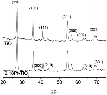 | ||
| Fig. 1 XRD patterns of the prepared TiO2 and 0.18 mol% Pt modified TiO2 (0.18Pt–TiO2). | ||
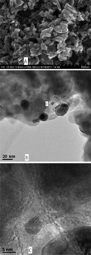
Fig. 2A shows the SEM images of the 0.18Pt–TiO2 sample. A lot of short nanorods were observed in the sample, which is similar to the pure rutile TiO2 (not shown). These nanorods were of 30–60 nm in diameter and less than 350 nm in length. The size and morphology of the sample were further analyzed by HRTEM. Pt nanoparticles were embedded in the TiO2 matrix, as shown in Fig. 2B. The Pt nanoparticles with sizes between 5 nm to 30 nm exhibited an uneven dispersion. The average size of 20 Pt nanoparticles in the TEM image was calculated to be 11 nm. Fig. 2C reveals the local crystal structure of the boundary between TiO2 and a Pt particle (the circle part at Fig. 2B). The TiO2 crystal lattice have a d-spacing of 0.32 nm, attributed to the (110) plane of the rutile-type TiO2 crystals. In the Pt particles, lattice fringes with a d-spacing of 0.22 nm are observed, which correspond to the (111) spacing of a f.c.c. Pt structure (JCPDS No. 65-2868). The distinguished interface and the continuity of the lattice fringes between the TiO2 and Pt nanoparticles confirms their strong interaction.21 It has been reported that the (110) facets of rutile TiO2 are prone to collect electrons,22 which greatly facilitates the transfer of electrons from the TiO2 to the Pt nanoparticles, and enhances the separation of holes and electrons.
Photocatalytic activity for the degradation of 2,4,6-TCP
Fig. 3A compares the kinetics of the photodegradation of 2,4,6-TCP under visible illumination in the presence of different catalysts. Negligible reaction was observed in the presence of pure rutile TiO2. Upon modification with Pt nanoparticles, the degradation rate of 2,4,6-TCP was markedly enhanced. It can be found that the degradation rate of 2,4,6-TCP is increased with increasing of the Pt content when it was below 0.18 mol%, and decreased with the increase of the Pt content when it was higher than 0.18 mol%. The rutile structure of TiO2 is known for the low photodegradation activity of organic species in aqueous solutions. This feature may be related to its ineffective oxygen reduction and efficient electron–hole pair recombination.23 For the Pt modified catalysts, photogenerated electrons are transferred from the rutile TiO2 conduction band to the Pt nanoparticles and the holes accumulate in the TiO2 valence band. O2 can be reduced by electrons at the Pt nanoparticles to ˙O2−, and in turn the reactive oxygen species form in the aqueous suspension.24,25 However, the Pt nanoparticle is itself an electron–hole recombination center.26 Thus, at high Pt nanoparticle concentration the increased electron–hole recombination rate on Pt has a larger deleterious effect than the increased oxygen reduction on Pt, which enhances photoactivity. This results in an optimum content of Pt being ∼0.18 mol%, where a higher content of Pt was detrimental to the enhancement of the photoactivity. Total organic carbon (TOC) experiments were performed to evaluate the mineralization ratio of 2,4,6-TCP in the presence of the 0.18Pt–TiO2 catalyst. The removal of TOC of 2,4,6-TCP was about 50% after 2.5 h illumination, and the TOC continued to decline afterwards, as observed in Fig. 3B. This means that 2,4,6-TCP and its organic degradation intermediates can be oxidized to harmless CO2, H2O and inorganic ions in this reaction system.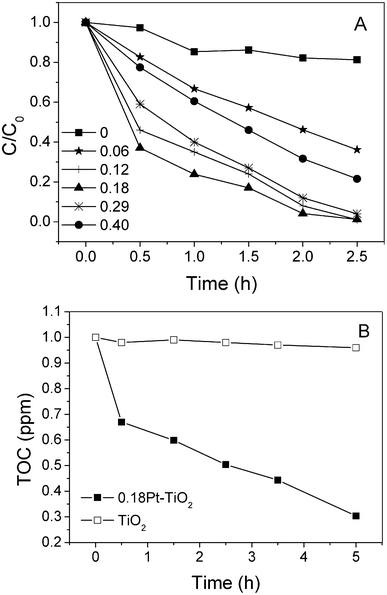 | ||
| Fig. 3 A) Photodegradation of 2,4,6-TCP in the presence of different Pt content catalysts. B) TOC removal of 2,4,6-TCP in the presence of 0.18Pt–TiO2 and pure TiO2 under visible light irradiation. | ||
The reaction solution was initially colorless, but it turned pink and decayed finally as the oxidation proceed in the presence of Pt nanoparticle-modified rutile TiO2. In the previously proposed mechanism for the TiO2-mediated photodegradation of aromatic organic pollutants, ˙OH was thought to be the main oxidative species for the degradation. Hydroquinones or catechols were the initial and main products formed by ˙OH attack on the para or ortho positions of the aromatic ring.27,28 These intermediates, produced from ˙OH attack, do not display a pink color in aqueous solution. The formation of a pink colored intermediate indicates that another oxidative species different from ˙OH is responsible for the photodegradation of 2,4,6-TCP.
Identification of the oxidative species and degradation intermediates
To study the main oxidative species for the degradation of 2,4,6-TCP, different oxidative species scavengers were added to the catalytic system, as shown in Fig. 4. The photodegradation of 2,4,6-TCP showed an insignificant decrease when ethanol, the ˙OH scavenger, was added in the presence of 0.18Pt–TiO2. This indicates that ˙OH is not the main oxidative species for the degradation of 2,4,6–TCP. It was observed that the addition of benzoquinone (BQ, a very efficient scavenger of ˙O2−) and Na2EDTA (a hole scavenger) both hindered the degradation of 2,4,6-TCP almost completely. The existence of a hole or electron scavenger would suppress their recombination and increase the lifetime of the separated electron and hole. The photodegadation should not be inhibited completely when BQ or Na2EDTA are added, if hole or ˙O2− act as the main oxidative species. This means that ˙O2− and the hole are involved in the formation of the reactive oxidative species, but they are not the direct oxidant for 2,4,6-TCP degradation. It was also observed that the degradation was inhibited by the addition of NaN3, an efficient quencher for ˙OH and 1O2. Rate constants for the hydroxyl radical and the singlet oxygen scavenging by NaN3 are 7.5 × 10⁹ and 5 × 10⁸ M−1 s−1,10 respectively. For comparison, in the case of ethanol these numbers are 1.5 × 10⁹ and ca. 103 M−1 s−1,10 respectively. The different effects of added NaN3 and ethanol on 2,4,6-TCP degradation indicated that 1O2 should be the main oxidative species.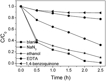 | ||
| Fig. 4 0.18Pt–TiO2 photocatalyzed degradation of 2,4,6-TCP in the presence of scavengers. | ||
The oxidation of chlorophenols by 1O2 was reported to result in the formation of hydroperoxides that dehydrated to form p-benzoquinone derivatives.29 The p-benzoquinone derivative of the photooxidation of 2,4,6-TCP should be 2,6-dichloro-1,4-benzoquinon (DCQ). The aqueous photoreaction of DCQ produced 2,6-dichlorohydroquinone and 2,6-dichloro-3-hydroxy-1,4-benzoquinone (DCHB) as reported earlier.30 DCQ, DCHQ and DCHB intermediates were observed in our experiments. 2,6-Dichloro-1,4-benzoquinon (DCQ) was identified by HPLC after comparison with authentic sample. 2,6-dichlorohydroquinone (DCHQ) and 2,6-dichloro-3-hydroxy-1,4-benzoquinone (DCHB) were identified by high performance liquid chromatography mass spectrometry (HPLC-MS) (Fig. S4, ESI†). UV-VIS absorbance at 524 nm, the source of the pink color, was observed during the photoreaction due to the formation of DCHB (Fig. S5, ESI†). It is reasonable to assume that the oxidation of 2,4,6-TCP by 1O2 in this way, Fig. 5. It was previously demonstrated that ˙N3 was generated during the quenching of 1O2 by NaN3.31 ˙N3 is a rather active oxidant that can react with 2,4,6-TCP, which lead to the photodegradation reaction of 2,4,6-TCP not being completely inhibited in the presence of NaN3.
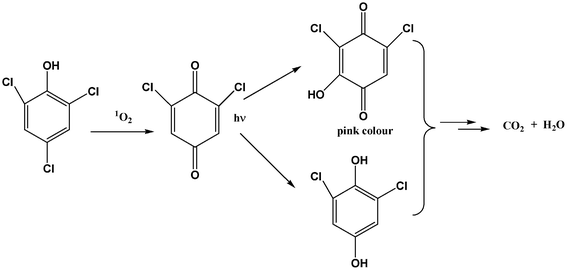 | ||
| Fig. 5 Oxidation pathway of 2,4,6-TCP by 1O2. | ||
We have further employed an ESR technique to detect the photogeneration of 1O2 by Pt–TiO2 using 2,2,6,6-tetramethyl piperidine (TEMP) as the spin trap under 355 nm and 532 nm laser illumination. As shown in Fig. 6A and 6B, the characteristic ESR spectra, containing three equal-intensity lines from nitrooxide radical (TEMPO), were successful determined during UV and visible illumination, and the signal intensity increased with the illumination time. The intensity of ESR signals illuminated at 355 nm is stronger than that illuminated at 532 nm after the same illumination time. This can be attributed to the strong absorbance of the catalyst at 355 nm that enhanced the formation of excited electrons, and then the formation of 1O2. Control experiments showed that the nitrooxide radical signal can not be observed in the presence of NaN3 after illumination at 355 nm for 180 s (Fig. S6, ESI†).
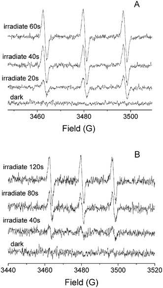 | ||
| Fig. 6 ESR spectra of TEMP-1O2 adducts in aqueous solution. A) 0.18Pt–TiO2 illuminated with 355 nm laser; B) 0.18Pt–TiO2 illuminated with 532 nm laser. | ||
Mechanism of singlet oxygen photogeneration
Hwang et al. reported recently that 1O2 can be formed through direct sensitization by PVP dispersed Pt nanoparticles.32 The formation of 1O2 on Pt/TiO2 was proposed to take place via the following possible mechanisms: 1) direct sensitization of Pt nanoparticles; 2) energy transfer as a result of electron–hole recombination; and 3) electron transfer process, reaction of superoxide anion with hole. The hole and ˙O2− scavenger would not affect the formation of 1O2 if it was generated by the sensitization of Pt nanoparticles embedded on TiO2. CTAB dispersed Pt nanoparticles in aqueous solution (1 g L−1) cannot catalyze the degradation of 2,4,6-TCP under photoexcitation in this research. So, the photodegradation of 2,4,6-TCP can not be explained by the direct photosensitization of Pt nanoparticles. It has been reported that Pt nanoparticles on TiO2 significantly enhance O2 adsorption and the formation of ˙O2−.26 The rutile surface is a favorable condition to stabilize ˙O2−.33 These properties of Pt nanoparticle-modified TiO2 facilitate the formation of 1O2via reaction of superoxide anions with holes, Fig. 7.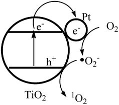 | ||
| Fig. 7 Formation mechanism of 1O2 on Pt nanoparticles modified rutile TiO2. | ||
The present work demonstrates the photogeneration of 1O2 and photodegradation of 2,4,6-TCP in the presence of Pt nanoparticle-modified rutile TiO2 under visible illumination. The Pt nanoparticles contribute to separating distinctly the charges of electrons and holes generated in TiO2 by visible illumination. O2 can be reduced by the conduction band electron to ·O2−, which is oxidized by a hole to 1O2. The formed 1O2 is then involved in the primary oxidation reaction of 2,4,6-TCP. The presented results may shine some light on the mechanism of 1O2 generation at the modified rutile TiO2 surface and chlorophenols oxidation. On the other hand, the visible photogeneration of 1O2 by the catalyst shows its potential application in photodynamic therapy and photooxidation of organic compounds.
Acknowledgements
The generous supports by the National Natural Science Foundation of China (No. 41076040, No. 20807036), the Chinese Academy of Sciences (KZCX2-YW-JS208) and the Yantai Science & Technology Bureau (Project 2010160) are acknowledged.References
- S. Z. Wang, R. M. Gao, F. M. Zhou and M. Selke, J. Mater. Chem., 2004, 14, 487–493 RSC.
- Y. Nosaka, T. Daimon, A. Y. Nosaka and Y. Murakami, Phys. Chem. Chem. Phys., 2004, 6, 2917–2918 RSC.
- M. R. Hoffmann, S. T. Martin, W. Choi and D. W. Bahnemann, Chem. Rev., 1995, 95, 69–96 CrossRef CAS.
- C. C. Chen, W. H. Ma and J. C. Zhao, Chem. Soc. Rev., 2010, 39, 4206–4219 RSC.
- M. C. DeRosa and R. J. Crutchley, Coord. Chem. Rev., 2002, 233–234, 351–371 CrossRef CAS.
- A. H. Dwivedi and U. C. Pande, Sci. Revs. Chem. Commun., 2012, 2, 41–65 Search PubMed.
- X. Z. Li, W. Zhao and J. C. Zhao, Sci. China, Ser. B: Chem., 2002, 45, 421–425 CrossRef CAS.
- M. Stylidi, D. I. Kondarides and X. E. Verykios, Appl. Catal., B, 2004, 47, 189–201 CrossRef CAS.
- T. Nyokong, Coord. Chem. Rev., 2007, 251, 1707–1722 CrossRef CAS.
- A. Janczyk, E. Krakowska, G. Stochel and W. Macyk, J. Am. Chem. Soc., 2006, 128, 15574–15575 CrossRef CAS.
- X. B. Chen and S. S. Mao, Chem. Rev., 2007, 107, 2891–2959 CrossRef CAS.
- H. Haick and Y. Paz, J. Phys. Chem. B, 2003, 107, 2319–2326 CrossRef CAS.
- C. Quinones, J. Ayala and W. Vallejo, Appl. Surf. Sci., 2010, 257, 367–371 CrossRef CAS.
- S. H. Joo, J. Y. Park, C. K. Tsung, Y. Yamada, P. D. Yang and G. A. Somorjai, Nat. Mater., 2008, 8, 126–131 CrossRef.
- M. Moonsiri, P. Rangsunvigit, S. Chavadej and E. Gulari, Chem. Eng. J., 2004, 97, 241–248 CrossRef CAS.
- C. B. Zhang, H. He and K. Tanaka, Catal. Commun., 2005, 6, 211–214 CrossRef CAS.
- J. R. Croy, S. Mostafa, J. Liu, Y. Sohn, H. Heinrich and B. R. Cuenya, Catal. Lett., 2007, 119, 209–216 CrossRef CAS.
- U. K. Kirner, K. D. Schierbaum and W. Göpel, Fresenius' J. Anal. Chem., 1991, 341, 416–420 CrossRef CAS.
- E. Kowalska, H. Remita, C. Colbeau, J. Hupka and J. Belloni, J. Phys. Chem. C, 2008, 112, 1124–1131 CAS.
- M. D. Driessen and V. H. Grassian, J. Phys. Chem. B, 1998, 102, 1418 CrossRef CAS.
- J. K. Lim, S. A. Majetich and R. D. Tilton, Langmuir, 2009, 25, 13384–13393 CrossRef CAS.
- E. Bae and T. Ohno, Appl. Catal., B, 2009, 91, 634–639 CrossRef CAS.
- T. Ohno, K. Sarukawa and M. Matsumura, J. Phys. Chem. B, 2001, 105, 2417–2420 CrossRef CAS.
- C. S. Turchi and D. F. Ollis, J. Catal., 1990, 122, 178–192 CrossRef CAS.
- L. Davydov and P. G. Smirniotis, J. Catal., 2000, 191, 105–115 CrossRef CAS.
- C. L. Muhich, Y. Zhou, A. M. Holder, A. W. Weimer and C. B. Musgrave, J. Phys. Chem. C, 2012, 116, 10138–10149 CAS.
- Y. Hou, X. Y. Li, Q. D. Zhao, X. Quan and G. H. Chen, Environ. Sci. Technol., 2010, 44, 5098–5103 CrossRef CAS.
- D. Zhao, C. C. Chen, Y. F. Wang, H. W. Ji, W. H. Ma, L. Zang and J. C. Zhao, J. Phys. Chem. C, 2008, 112, 5993–6001 CAS.
- K. Ozoemena, N. Kuznetsova and T. Nyokong, J. Mol. Catal. A: Chem., 2001, 176, 29–40 CrossRef CAS.
- G. Lente and J. H. Espenson, J. Photochem. Photobiol., A, 2004, 163, 249–258 CrossRef CAS.
- J. R. Harbour and S. L. Issler, J. Am. Chem. Soc., 1982, 104, 903–905 CrossRef CAS.
- R. Vankayala, A. Sagadevan, P. Vijayaraghavan, C. L. Kuo and K. C. Hwang, Angew. Chem., Int. Ed., 2011, 50, 10640–10644 CrossRef CAS.
- T. Hirakawa, K. Yawata and Y. Nosaka, Appl. Catal., A, 2007, 325, 105–111 CrossRef CAS.
Footnote |
| † Electronic Supplementary Information (ESI) available. See DOI: 10.1039/c2ra21661b |
| This journal is © The Royal Society of Chemistry 2012 |

