Ce–Ni mixed oxide as efficient catalyst for H2 production and nanofibrous carbon material from ethanol in the presence of water
Wenhao
Fang
ab,
Cyril
Pirez
ab,
Mickaël
Capron
ab,
Sébastien
Paul
abc,
Thirumalaiswamy
Raja
d,
Paresh L.
Dhepe
d,
Franck
Dumeignil
abe and
Louise
Jalowiecki-Duhamel
*ab
aUniv. Lille Nord de France, F-59000, Lille, France. E-mail: louise.duhamel@univ-lille1.fr
bCNRS UMR8181, Unité de Catalyse et Chimie du Solide, UCCS, F-59655, Villeneuve d'Ascq, France
cECLille, F-59655, Villeneuve d'Ascq, France
dNational Chemical Laboratory, Catalysis Division, Pune, Maharashtra 411008, India
eInstitut Universitaire de France, Maison des Universités, 103 Boulevard Saint-Michel, Paris, 75005, France
First published on 15th August 2012
Abstract
Hydrogen production from ethanol steam reforming (H2O/C2H5OH = 3) was studied over Ce–Ni based catalysts issued from different preparation methods (co-precipitation (CP), impregnation (IMP) and incipient wetness impregnation (IWI)). Catalysts prepared by the CP method exhibit higher activity and much better stability compared to the other two types of catalysts. The Ni1CeOY–CP catalyst is able to completely convert ethanol at 450 °C to H2, CO2 and CH4 (almost no CO is observed), with a H2 yield of 3 moles of hydrogen produced per mole of ethanol converted. A very high H2 yield of 4.6 mol molEtOH−1 is achieved over the Ni1CeOY–CP mixed oxide at 650 °C. Correlations between the preparation method, catalytic activity and stability, and type of carbon deposition are discussed. The CP method forms very active small sized NiO (15 nm) and CeO2 (4 nm) nanoparticles, leading to the formation of a lower amount of carbon deposition in the form of nanofibrous carbon materials, the size of which depends on the Ni related nanoparticles. For CP catalysts, the graphitic filaments obtained correspond to carbon nanofibers (CNFs) and carbon nanotubes (CNTs) with a much smaller and homogenous size compared to the filamentous carbon formed over the catalysts issued from the other preparation methods, in relation to the active particles size. The catalytic stability is attributed to the type of carbon formed.
Introduction
In the 21st century, human beings are not able to evade the expanding problems coming from fossil fuels. As non-renewable energy sources, the exploitation and utilization of fossil fuels have caused a series of social and environmental issues. Therefore, developing renewable and clean energy sources to substitute conventional energy resources has become the mainstream development strategy in the present world.Hydrogen is regarded as one of the most energy-efficient fuel sources based on its high efficiency and cleaness.1–5 Hydrogen, which can be used directly as a fuel in internal combustion engines or indirectly supply electricity via fuel cells, is environmentally benign. Producing hydrogen in a sustainable way from environmentally friendly and promising renewable sources has become an exciting research area on both laboratory and industrial scales. Bio-ethanol, mainly a mixture of water and ethanol largely obtained from biomass via a fermentation process, is proposed to be one of the most interesting H-containing carriers among all the candidates derived from biomass.6–14 Thus, the steam reforming of ethanol (SRE) is a very desirable route to produce hydrogen (eqn (1)).
| C2H5OH + 3H2O → 6H2 + 2CO2 | (1) |
However, SRE actually involves a complicated reaction network, accompanied by many possible byproducts, related mainly to the catalyst used. In such a context, it is a major challenge today to develop a highly active, selective, stable and low-cost catalyst which is able to efficiently break the C–C bond of bio-ethanol. Noble metal catalysts, such as Pd, Ru, Rh and Pt, have been well studied and exhibit good activity in SRE at 500–600 °C.12–14 However, it is obviously not an ideal and sustainable option due to the high price of the noble metals and their availability.
To avoid these problems non-noble metals have also been largely studied.12–17 Among them nickel-based catalysts have been extensively and widely employed in the steam reforming of ethanol because of their good capability towards C–C bond rupture.18–24 However, it has often been reported that nickel favors coke deposition, leading to the deactivation of the catalyst. Meanwhile, carbon can exist in different forms and carbon nano-materials are strategic materials in nano-technologies. Recently, it has been shown that the chemical decomposition of biomass materials like ethanol is another way to produce hydrogen and several papers have reported the production of carbon nanotubes (CNTs) accompanied by hydrogen production during ethanol decomposition.25,26
Better catalytic performances with high stability and high hydrogen selectivity can be expected over a support such as CeO2, which is able to maintain smaller metal catalyst particles by strong metal–support bonding.27 Ceria, a fluorite-type oxide, has been applied to various reactions in order to take advantage of its oxygen storage and/or oxygen diffusion properties. The release and uptake of oxygen by ceria allows it to participate in redox reactions and the enhancement of the formation of oxygen vacancies due to the reduction of cerium cations has been shown to be important for catalytic activity.28,29,33 It is well known that the metal–support interactions play an important role during the preparation step and the thermal treatment, since both of them are able to define the properties of the final catalysts: reducibility, resistance to thermal sintering of the active sites or metallic dispersion. Moreover, the reducibility, catalytic activity and coking resistant behaviors of catalysts are affected by their surface and structural properties, so that the methodology involved in the preparation step can lead to the obtainment of materials with important properties for applications in catalytic processes, such as the steam reforming of ethanol. The effects of the catalyst synthesis method on the characteristics and performance of Ni/Al2O3 catalysts were evaluated for the reforming of crude ethanol for H2 production. Catalysts with a 15% Ni loading gave the best crude ethanol conversions for each synthesis method but in terms of the H2 yield, CP15 was the optimum catalyst because of its higher H2 selectivity.30 There are few reports on the preparation methodology of Ce–Ni materials for hydrogen production from ethanol reforming.
In our laboratory, Ce–Ni mixed oxides have been largely studied due to the strong interactions which exist between the nickel and cerium species inside the solid.31–33 In the present study, Ce–Ni based catalysts are synthesized using different preparation methods to explore the factors which benefit the reaction process. We report Ce–Ni mixed oxides as highly efficient and stable catalysts for the production of hydrogen and carbon nano-materials from the steam reforming of ethanol. It is shown that tuning the catalyst allows us to obtain not only a very active catalyst for hydrogen production but also the formation of carbon nano-materials, as an added bonus. To our knowledge, the production of carbon nanofibers (CNFs) and carbon nanotubes (CNTs) accompanied by high hydrogen production during ethanol steam reforming has not been reported under mild conditions. Compared to ethanol decomposition, working in presence of water allows for the use of bio-ethanol and avoids some of the costly steps involved in purification.
Experimental
Catalyst preparation
The catalyst samples denoted as NiXCeOY–CP, x-NiCeO2–IMP and x-NiCeO2–IWI (where X corresponds to the Ni/Ce molar ratio and x corresponds to the Ni wt%) were prepared by co-precipitation (CP), impregnation (IMP) and incipient wetness impregnation (IWI) methods, respectively. The NiXCeOY–CP mixed oxides were prepared by the co-precipitation of the corresponding hydroxides from mixtures of nickel and cerium nitrates, using triethylamine (TEA) as a precipitating agent. After filtration, the solids were dried at 100 °C and calcined in air at 500 °C for 4 h. The x-NiCeO2–IMP catalysts were prepared by adding the CeO2 support into the corresponding nickel nitrate solution (20 cm3) and after stirring overnight, the slurry was dried under vacuum and calcined in air at 500 °C for 4 h. For the x-NiCeO2–IWI catalyst, a very small quantity of the corresponding nickel nitrate solution was slowly added into the CeO2 support, followed by standing overnight. The wet support was then dried under vacuum and calcined in air at 500 °C for 4 h. The CeO2 support comes from commercial samples (S.d Fine Chem LTD-Mumbai).Catalytic reaction
The catalytic performance of the steam reforming of ethanol was conducted under atmospheric pressure in a fixed-bed flow quartz reactor (inner diameter of 8 mm or 4 mm). The heating of the reactor was provided by a programmable oven. The catalyst (200, 50 or 8 mg) was previously treated in situ in H2 at 250 °C for 10 h. The water–ethanol mixture, with a stoichiometric molar ratio of 3 (42 mol% of H2O and 14 mol% of C2H5OH or, in highly diluted conditions, 9 mol% of H2O and 3 mol% of C2H5OH), was injected into a heating chamber by an HPLC pump and then the vaporized steam was fed into the reactor, using N2 as a carrier, with a total flow rate of 60 cm3 min−1. The feed and product outlet gases were analyzed online by gas chromatography (TRACE GC ULTRA) equipped with a thermal-conductivity detector (TCD) and a flame ionization detector (FID).The catalytic performance is reported based on the ethanol conversion ( ), product composition (Ci) and H2 yield (
 ), which are calculated by the following equations (eqn (2)–(4)).
 | (2) |
 is the molar flow rate of ethanol at the inlet/outlet of the reactor respectively.
  | (3) |
 | (4) |
Catalyst characterization
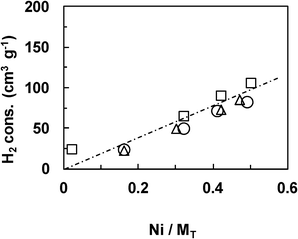
The Ni loading was analyzed by the ICP-MS technique (Centre d'analyses CNRS Vernaison). For the NiXCeOY–CP mixed oxides, the Ni/MT ratio is the nickel molar proportion among all the metals (MT = X + 1, Ni/MT = X/(X + 1)).The BET specific surface areas were measured by N2 physisorption using a TriStar II 3020 surface-area and porosimetry analyzer. Samples were previously out-gassed under vacuum at 150 °C for 3 h.
X-ray powder diffraction (XRD) analysis was carried out with a D 5000 Siemens diffractometer using a copper target and a secondary beam monochromator. The XRD patterns were registered in the 2θ domain (20–90°) with a measured step of 0.02° and the time integration was fixed to 0.3 s. The crystallite size was calculated using the Scherrer equation.
Temperature-programmed reduction (H2–TPR) was performed with a Micromeritics Autochem 2920 analyzer and the hydrogen consumption was measured by a TCD detector. 50 mg of the sample was treated in 5 vol% H2–95 vol% Ar mixtures with a flow rate of 30 cm3 min−1. The temperature was increased to 1000 °C at a heating rate of 10 °C min−1.
Temperature-programmed oxidation (O2–TPO) was performed with a Micromeritics Autochem 2920 analyzer. 50 mg of the sample was treated in 5 vol% O2–95 vol% He mixtures with a flow rate of 50 cm3 min−1. The temperature was increased to 950 °C at a heating rate of 5 °C min−1. The desorption species from the sample were detected using a OmniStar GSD 300 O mass spectrometer.
Transmission electron microscopy (TEM) images were obtained by a Philips CM30 transmission electron microscope at an acceleration voltage of 300 kV. The sample was previously ultrasonically dispersed in acetone and drops of the suspension were then applied onto a copper grid-supported transparent carbon film.
Raman spectra of the carbonaceous species were carried out on a Labram Infinity HORIBA JOBIN YVON Raman spectrometer. The patterns were recorded at a wavelength of 532 nm.
Results and discussion
Characterizations on the Ce–Ni based catalysts prepared by different methods
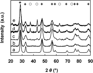 | ||
Fig. 1 XRD patterns of the NiXCeOY–CP catalysts. a) X = 0 (CeO2), b) X = 0.02, c) X = 0.5, d) X = 0.72, e) X = 1. ( : CeO2, ○: NiO). : CeO2, ○: NiO). | ||
| Catalyst | S. A. /m2 g−1 | NiO /nm | CeO2 /nm |
|---|---|---|---|
| Ni0.5CeOY–CP (x = 13) | 109 | 8 | 5 |
| Ni0.72CeOY–CP (x = 18) | 109 | 12 | 5 |
| Ni1CeOY–CP (x = 24) | 119 | 15 | 4 |
| 6-NiCeO2–IMP | 6 | 20 | 35 |
| 13-NiCeO2–IMP | 7 | 30 | 37 |
| 18-NiCeO2–IMP | 8 | 34 | 37 |
| 23-NiCeO2–IMP | 6 | 38 | 38 |
| 6-NiCeO2–IWI | 6 | 19 | 37 |
| 12-NiCeO2–IWI | 7 | 27 | 36 |
| 18-NiCeO2–IWI | 7 | 26 | 38 |
| 22-NiCeO2–IWI | 7 | 38 | 36 |
The diffraction patterns become much more intense when the impregnation method is employed (Fig. 2), which indicates that very well-crystallized materials are formed, in relation to the well-crystallized ceria used. Peaks assigned to the CeO2 phase are detected in each sample and the characteristic diffractions of the NiO phase emerge when x≥13 wt%. The given XRD patterns are likely to be characteristic of a mixture of NiO and CeO2 phases in various proportions depending on the Ni loading. Almost the same XRD results are obtained over the x-NiCeO2–IWI and IMP samples.
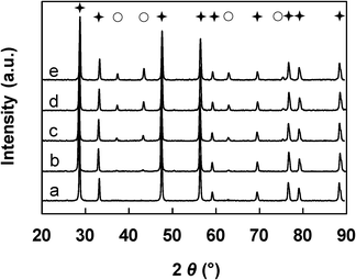 | ||
Fig. 2 XRD patterns of the x-NiCeO2–IMP catalysts. a) x = 0 (CeO2), b) x = 6, c) x = 13, d) x = 18, e) x = 23. ( : CeO2, ○: NiO). : CeO2, ○: NiO). | ||
In a similar manner as previously established, the crystallite sizes of both NiO and CeO2 were estimated from the diffraction lines, taking into account the (111), (200) and (220) peaks. The average dimensions for the Ce–Ni based catalysts prepared by various methods are summarized in Table 1. The average crystallite size of the CeO2 particles from the same preparation method does not have a large variation, while the NiO average particle size becomes larger in the same series with higher Ni content. The IMP and IWI methods lead to materials with NiO particles ranging from 20 nm up to 40 nm and CeO2 particles of around 37 nm. Compared to those two types of catalysts, the CP method leads to mixed oxides with much smaller NiO and CeO2 nanoparticle sizes. The size of the nanoparticles are between 8 and 15 nm depending on the Ni content and the CeO2 nanoparticle sizes are consistently less than 5 nm. It is necessary to recall that crystallites with a size which is less than 2 nm can not be detected by XRD due to the limits of detection. However, such small NiO nanoparticles have been shown to be present in the CP mixed oxides.34,35
The surface areas are also listed in Table 1. The NiXCeOY–CP mixed oxides present much larger specific surface areas (about 110 m2 g−1) compared to the samples from the IMP and IWI methods (7 m2 g−1) whatever the Ni loading. The surface areas of the IMP and IWI compounds are related to the surface area of commercial CeO2.
| Ni2+ + O2− + H2 → Ni0 + H2O + □ (□: anionic vacancy) | (5) |
| 2Ce4+ + Ni0 ↔ 2Ce3+ + Ni2+ | (6) |
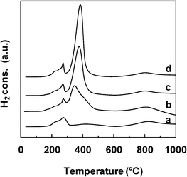 | ||
| Fig. 3 TPR profiles of the NiXCeOY–CP catalysts. a) X = 0.1 b) X = 0.5, c) X = 0.7, d) X = 1. | ||
 | ||
| Fig. 4 TPR in H2 of the Ce–Ni based catalysts. (CP: □, IMP: ○, IWI: △). | ||
The reductive properties of the Ce–Ni based catalysts prepared by various methods but with a similar Ni content are compared in Fig. 5. The main reduction peak is found at about 400 °C for all catalyst types and this peak shifts slightly towards lower temperatures over the Ni1CeOY–CP sample. More interestingly, the small peak at around 270 °C, clearly present on the Ni1CeOY–CP mixed oxide, is not observed on the 23-NiCeO2–IMP and the 22-NiCeO2–IWI catalysts, confirming the attribution of this TPR peak to the presence of the nickel species in small NiO nanoparticles and/or solid solutions.35 It has to be remarked upon that this phenomenon has been verified for different Ni contents. Therefore, the CP method produces mixed oxides with much smaller NiO and CeO2 particle sizes, increasing the number of strong interactions between the Ni and Ce species and leading to compounds that can be easily and reversibly reduced and reoxidized.28,35 Furthermore, it is commonly reported that a TPR analysis of CeO2 presents two peaks at about 500 °C and 820 °C and thus the reduction peak obtained at around 820 °C is ascribed to the reduction of bulk Ce4+ to Ce3+.
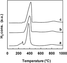 | ||
| Fig. 5 TPR profiles of the Ce–Ni based catalysts prepared by various methods. a) Ni1CeOY–CP, b) 23-NiCeO2–IMP, c) 22-NiCeO2–IWI. | ||
Catalytic performances of the Ce–Ni based catalysts prepared by different methods
To investigate the effect of the Ni content, a series of NiXCeOY–CP mixed oxides with various Ni contents were evaluated at 450 °C using 50 mg of the solid. Meanwhile, the results from the IMP and IWI catalysts with different Ni loadings were also compared to the curve obtained for the NiXCeOY–CP mixed oxides. It is clearly shown in Fig. 6 that the catalytic activity depends mainly on the Ni content of the catalysts, no matter what preparation method is employed. Ethanol conversion increases with Ni content and reaches 100% when the Ni/MT molar ratio is higher or equal to 0.5 (around 20 wt% Ni). H2 formation decreases from about 70% (in mol.) to around 45% when increasing the Ni/MT molar ratio. This can be due to the high conversion of ethanol that is injected in high concentrations and so leads to a high production of gases. The gas phase product distribution follows relatively similar evolutions, as shown in Fig. 7. Acetone and acetaldehyde are only formed over catalysts with low Ni content and disappear when Ni/MT≥0.5. CO2 formation shows a gradual increase with the Ni content, whereas the CO and CH4 formation present a maximum at Ni/MT = 0.5, where the CO2 and CO products do not fit to the curve. This phenomenon is certainly due to the very high conversion of ethanol over the Ni1CeOY–CP catalyst, leading to a higher concentration of CO2.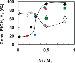 | ||
Fig. 6 SRE at 450 °C over Ce–Ni based catalysts versus Ni content. Ethanol conversion (♦) and H2 production (⋄) over 50 mg of the catalyst (CP: black, IMP: red, IWI: blue) and over 8 mg of the CP catalyst: ( ) conversion and (△) H2. ) conversion and (△) H2. | ||
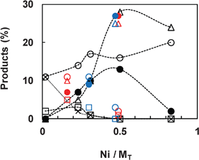 | ||
| Fig. 7 Product composition versus Ni content over the Ce–Ni based catalysts (50 mg) in SRE at 450 °C. (○: CO2, •: CO, △: CH4, , □: acetaldehyde, ×: acetone; CP: black, IMP: red, IWI: blue). | ||
It must be noted that all the results reported over the NiXCeOY–CP catalysts are obtained after 5 h of reaction. Carbon deposition is observed, as expected, but nevertheless no deactivation is detected. On the contrary, when testing the IMP and IWI catalysts, a dramatic increase of the pressure inside the catalytic system takes place, requiring a discontinuation of the catalytic test after 1 h. This phenomenon is observed independently of the Ni loading, indicating that the NiXCeOY–CP mixed oxides are far more stable than the other two types of catalysts. It can be expected that different types of carbon or carbonaceous species are formed.
Due to the difficulty in comparing the catalytic results with the total conversion of ethanol, two CP catalysts with Ni/MT≥0.5 were also analyzed using 8 mg of the catalyst (Fig. 6). It appears that the ethanol conversion increases with Ni content and H2 is found at about 64%. The distribution of the other products is also influenced (Table 2). When increasing the Ni content, CO increases while acetaldehyde decreases. In such conditions, even if the highest H2 formation of 7 g h−1 gcat−1 can be reported over the Ni5CeOY–CP catalyst, the carbon deposit is very high and the reaction has to be stopped for this compound after one hour of testing due to an increase in the pressure in the catalytic test.
Over a high catalytic mass (200 mg), very similar results are obtained regardless of the preparation method (Table 3). It is obvious that there is almost no difference between the catalysts prepared by various methods but with approximately the same Ni content of 23 wt%. Ethanol conversions all reach 100% at 450 °C over 200 mg of the catalysts. Carbon deposition is formed but not reported under these conditions. It is important to note that in such conditions, the activity exhibits stability after a reaction time of 5 h for all the catalysts. It seems that when the catalytic mass is higher than what is required for the total conversion of ethanol, a part of the catalyst can be used to remove or help to remove carbon. However, it is impossible to analyze the influence of the preparation method with the total conversion of ethanol.
| Catalyst | Conv. /% | Products /% | Carbon formation /g h−1 gcat−1 | |||
|---|---|---|---|---|---|---|
| H2 | CO2 | CO | CH4 | |||
| a 200 mg of catalyst, time: 5 h. b 50 mg of catalyst. c Time: 1 h. d Not determined. | ||||||
| Ni1CeOY–CPa | 100 | 47 | 20 | 2 | 31 | n.d.d |
| 23-NiCeO2–IMPa | 100 | 49 | 23 | 2 | 26 | n.d.d |
| 22-NiCeO2–IWIa | 100 | 49 | 23 | 2 | 26 | n.d.d |
| Ni1CeOY–CPb | 95 | 43 | 16 | 13 | 28 | 1.1 |
| 23-NiCeO2–IMPb | 83c | 45 | 2 | 28 | 25 | 2.1 |
| 22-NiCeO2–IWIb | 87c | 45 | 3 | 27 | 25 | 2.1 |
When 50 mg of the catalyst is evaluated, the Ni1CeOY–CP mixed oxide presents a very high activity which attracted our interest. Ethanol is almost completely converted at 450 °C (Table 3), while the catalysts prepared by the IMP and IWI methods show a relatively low ethanol conversion, although it is still very high at 85%. H2, CO2, CO and CH4 are the main products detected in the gas phase. The same product distribution is observed over the 23-NiCeO2–IMP and the 22-NiCeO2–IWI catalysts, whereas the Ni1CeOY–CP mixed oxide gives a higher CO2 formation and a lower CO formation. Carbon deposition is found after the reaction and precisely measured. The carbon deposit, with a formation rate of 1.1 g h−1 gcat−1, is generated over the Ni1CeOY–CP mixed oxide (measured after a reaction time of 5 h ), but no deactivation is detected. Over the 23-NiCeO2–IMP and the 22-NiCeO2–IWI catalysts, a much higher carbon formation rate of 2.1 g h−1 gcat−1 is observed. The CP method leads to the best results found for the Ni/Al2O3 catalysts, even though a 15 wt% Ni loading gave the highest H2 yield in the studied series.30
The efficiency of the Ni1CeOY–CP catalyst was thoroughly studied by its capacity to produce hydrogen from SRE. Fig. 8 reports the ethanol conversion and the gas phase products with the time on the stream in diluted conditions (to avoid any problems due to volume variation when a high concentration of gases are produced). At 450 °C, the Ni1CeOY–CP catalyst is able to completely convert ethanol to H2, CO2 and CH4 (almost no CO is observed), with a H2 yield of 3 mol molEtOH−1. By increasing the reaction temperature from 450 °C up to 650 °C, CH4 formation gradually decreases from 20% down to zero, while CO formation starts rising to about 13%, in agreement with methane reforming at high temperatures and CO transformation by a water gas shift at low temperatures. As a result, the yield of hydrogen significantly increases up to 4.6 mol molEtOH−1 at 650 °C (Fig. 8), while the catalyst exhibits considerable stability. It has to be noted that a carbon formation of 15 mg h−1 gcat−1 is measured over the Ni1CeOY–CP catalyst after a reaction time of 10 h at 650 °C in such conditions. The catalytic performance is also reported over only 8 mg of the catalyst and a H2 production of 2.8 g h−1 gcat−1 is obtained at 450 °C over the Ni1CeOY–CP catalyst at a relatively stable state after 5 h (Table 4). However, in such cases, some CO and acetaldehyde are also formed, certainly due to the low amount of catalyst used.
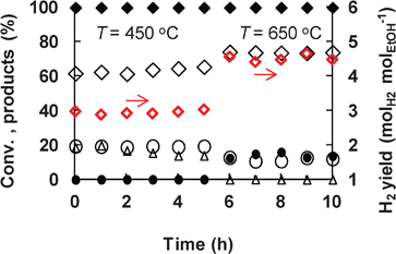 | ||
Fig. 8 SRE over the Ni1CeOY–CP catalyst (50 mg). ( H2 yield, ♦ ethanol conversion, ⋄: H2, ○: CO2, •: CO, △: CH4). Reaction conditions: H2O: 9 mol%; C2H5OH: 3 mol%. H2 yield, ♦ ethanol conversion, ⋄: H2, ○: CO2, •: CO, △: CH4). Reaction conditions: H2O: 9 mol%; C2H5OH: 3 mol%. | ||
To the best of our knowledge, this is the best hydrogen yield that has ever been reported under such relatively mild conditions in steam reforming of ethanol.13,14 The value of 4.6 mol molEtOH−1 with the present Ni1CeOY–CP catalyst is better than those measured with other nickel-based catalysts, such as Ce–NiMgAl (≈4.0 over 150 mg of catalyst), Ni50ZnAl (≈5.0 with H2O/C2H5OH = 6) and Ni/Mg2Al (≈5.1 with H2O/C2H5OH = 8.4), when taking into account the reaction conditions.36–38 It must be emphasized that the hydrogen production can be promoted by increasing the water partial pressure and the H2O/C2H5OH molar ratio.39
Characterizations on the spent Ce–Ni catalysts prepared by different methods
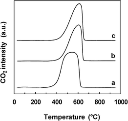 | ||
| Fig. 9 TPO profiles of the spent Ce–Ni based catalysts prepared by different methods. a) Ni1CeOY–CP, b) 23-NiCeO2–IMP, c) 22-NiCeO2–IWI. | ||
In the literature, temperatures around 510 °C were assigned to the combustion of single walled carbon nanotubes (SWNTs) and around 610 °C to multiwalled carbon nanotubes (MWNTs). Carbon nanofibers (CNFs) were supposed to burn off at lower temperatures than SWNTs.40 However, it is important to note that the carbon formed in the present study was analyzed without further purification and this step can also influence the results.
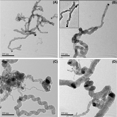 | ||
| Fig. 10 TEM micrographs for the spent Ce–Ni based catalysts prepared by different methods. (A) and (B) Ni1CeOY–CP catalyst after a reaction time of 5 h at 450 °C, within (B) a magnification of a CNT, (C) 23-NiCeO2–IMP catalyst after a reaction time of 1 h at 450 °C, (D) 22-NiCeO2–IWI catalyst after a reaction time of 1 h at 450 °C. | ||
The particles related to the Ni species in the IMP and IWI catalysts are no doubt much bigger in size compared to those in the Ni1CeOY–CP catalyst. The mean particle size is around 40 nm, in accordance with the value calculated from the XRD analysis over the fresh catalysts. A few small sized Ni particles are also observed, which could explain the relatively high activity of the 23-NiCeO2–IMP and the 22-NiCeO2–IWI catalysts. It has to be noted that almost all the big Ni related particles are observed to be blocked inside the spiral carbon, revealing the different growth mechanisms of the filamentous carbon. As a matter of fact, it is demonstrated that the growth rate of filamentous carbon increases with increasing nickel particle sizes.
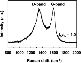 | ||
| Fig. 11 Raman spectra of the carbon deposition formed over the Ni1CeOY–CP catalyst in SRE. | ||
Red'kin et al. showed that during pyrolysis on a nickel catalyst, the ethanol molecules led to a sequence of chemical transformations, eventually decomposing into hydrogen, methane and carbon monoxide. It has been proposed that in the temperature range of 400–600 °C, the last gas disproportionates to give solid nanofibrous carbon material (nanotubes and nanofibers).45 Varying the process conditions, one can obtain carbon nanofibers of various thicknesses or carbon nanotubes,46 and the diameter of filamentous carbon is related to the metal particle size.42,47 Nano-sized carbon filaments were also grown on polycrystalline nickel foam, using the catalytic decomposition of ethanol (i.e. in the absence of water).48 It is generally accepted that carbon growth takes place on the nickel particle.49 The nickel nanoparticles formed on the surface of the nickel foam acted as catalytic sites where the filamentous carbons started to grow. These nanoparticles were mostly observed at the tip of the filaments. It has been observed that most filaments were CNFs and CNTs were formed at higher synthesis temperatures. Nanoparticles less than 50 nm in diameter led to the formation of filamentous carbon of the same size. After the catalytic decomposition of ethanol on a NiAl catalyst, heterogeneous filaments were formed. CNFs were present at 500 °C but when the reaction was conducted at 700 °C, MWCNTs were formed.25
As CNFs and CNTs are observed in the present study, it can be proposed that ethanol can also be decomposed in the presence of water. It can therefore be expected that varying the experimental conditions will also lead to different filamentous carbon, but this was not the aim of the present study.
The small sized NiO and CeO2 nanoparticles are confirmed to enhance the strong interactions between the nickel and cerium species. This not only leads to very high activities but also means the stability can be maintained due to the formation of filamentous carbon, the size of which is directly related to the size of the active particles. The interactions of the nickel and cerium species are enhanced due to the small NiO and CeO2 nanoparticles in the Ni1CeOY–CP mixed oxide, giving rise to a type of filamentous carbon which contributes to the catalytic stability.
Conclusions
We have successfully developed a simple co-precipitation method to fabricate highly efficient NiXCeOY mixed oxides as heterogeneous catalysts for H2 production from the steam reforming of bio-ethanol. At the same time, the impregnation and incipient wetness impregnation methods were also employed to synthesize Ce–Ni based catalysts for comparison. The Ni content exhibits a significant influence on the activity, no matter what kind of preparation method is involved. More importantly, the size of the NiO and CeO2 particles and the interactions of the nickel and cerium species, both of which are defined by the methodology of preparation, play key roles in determining the catalytic activity and stability. The co-precipitation method produces NiXCeOY mixed oxides with a much higher proportion of very active small NiO nanoparticles which can be reduced and reoxidized easily and reversibly due to the existence of strong interactions between the nickel and cerium species. At 450 °C, the Ni1CeOY–CP catalyst achieves a H2 yield of 2.8 g h−1 gcat−1 and/or 3 mol molEtOH−1 in different optimized conditions and on increasing the reaction temperature to 650 °C, this value increases up to 4.6 mol molEtOH−1. This is one of the best values ever reported under mild conditions and involving a low cost catalyst. Furthermore, the type of carbon formed during the reaction is strongly associated with the catalytic stability. The graphitic filamentous carbon, small and homogeneous in size and generated over the Ni1CeOY–CP catalyst explains the catalytic stability.Acknowledgements
This work is carried out as a part of collaboration under International Associated Laboratory programme between UCCS (CNRS) and NCL (CSIR). W. Fang gratefully acknowledges a grant from Erasmus Mundus Tandem. C. Pirez gratefully acknowledges a grant from the French Ministry. The authors would like to thank Ms. L. Burylo (XRD), Mr. O. Gardoll (TPR, TPO) and Mr. J. C. Morin (Raman) from UCCS and Mr A. Addad (TEM) from the “Centre Commun de Microscopie” (CCM) of the University of Lille, “plateau technique de la Fédération Chevreul CNRS FR 2638”, for their valued technical help. The “Fonds Européen de Développement Régional (FEDER)”, “CNRS”, “Région Nord Pas-de-Calais” and “Ministère de l'Education Nationale de l'Enseignement Supérieur et de la Recherche” are also acknowledged for the funding of XRD.References
- G. A. Deluga, J. R. Salge, L. D. Schmidt and X. E. Verykios, Science, 2004, 303, 993 CrossRef CAS.
- A. Midilli, M. Ay, I. Dincer and M. A. Rosen, Renewable Sustainable Energy Rev., 2005, 9, 273 CrossRef.
- A. Haryanto, S. Fernando, N. Murali and S. Adhikari, Energy Fuels, 2005, 19, 2098 CrossRef CAS.
- M. Momirlan and T. N. Veziroglu, Int. J. Hydrogen Energy, 2005, 30, 795 CrossRef CAS.
- M. Ni, D. Y. C. Leung and M. K. H. Leung, Int. J. Hydrogen Energy, 2007, 32, 3238 CrossRef CAS.
- L. De Rogatis, T. Montini, B. Lorenzut and P. Fornasiero, Energy Environ. Sci., 2008, 1, 501 CAS.
- R. M. Navarro, M. C. Sanchez- Sanchez, M. C. Alvarez-Galvan, F. del Valle and J. L. G. Fierro, Energy Environ. Sci., 2009, 2, 35 CAS.
- P. Leung, A. Tsolakis, J. Rodrıguez-Fernandez and S. Golunski, Energy Environ. Sci., 2010, 3, 780 CAS.
- P. K. Seelam, M. Huuhtanen, A. Sápi, M. Szabó, K. Kordás, E. Turpeinen, G. Tóth and R. L. Keiski, Int. J. Hydrogen Energy, 2010, 35, 12588 CrossRef CAS.
- X. Wu and S. Kawi, Energy Environ. Sci., 2010, 3, 334 CAS.
- G. P. Szijjártó, A. Tompos and J. L. Margitfavi, Appl. Catal., A, 2011, 391, 417 CrossRef.
- A. Iulianelli and A. Basile, Catal. Sci. Technol., 2011, 1, 366 CAS.
- N. Bion, D. Duprez and F. Epron, ChemSusChem, 2012, 5, 76 CrossRef CAS.
- L. V. Mattos, G. Jacobs, B. H. Davis and F. B. Noronha, Chem. Rev., 2012, 112, 4094 CrossRef CAS.
- J. Llorca, P. Ramírez de la Piscina, J. Sales and N. Homs, Chem. Commun., 2001, 641 RSC.
- M. Domínguez, E. Taboad, H. Idriss, E. Molins and J. Llorca, J. Mater. Chem., 2010, 20, 4875 RSC.
- R. Espinal, E. Taboada, E. Molins, R. J. Chimentao, F. Medina and J. Llorca, RSC Adv., 2012, 2, 2946 RSC.
- A. N. Fatsikostas, D. I. Kondarides and X. E. Verykios, Chem. Commun., 2001, 851 RSC.
- F. Mariño, M. Boveri, G. Baronetti and M. Laborde, Int. J. Hydrogen Energy, 2001, 26, 665 CrossRef.
- V. Fierro, V. Klouz, O. Akdim and C. Mirodatos, Catal. Today, 2002, 75, 141 CrossRef CAS.
- V. Fierro, O. Akdim and C. Mirodatos, Green Chem., 2003, 5, 20 RSC.
- G. Zhou, L. Barrio, S. Agnoli, S. D. Senanayake, J. Evans, A. Kubacka, M. Estrella, J. C. Hanson, A. Martínez-Arias, M. Fernández-García and J. A. Rodriguez, Angew. Chem., Int. Ed., 2010, 49, 9680 CrossRef CAS.
- N. Zhu, X. Dong, Z. Liu, G. Zhang, W. Jin and N. Xu, Chem. Commun., 2012, 48, 7137 RSC.
- C. Zhang, P. Zhang, S. Li, G. Wu, X. Ma and J. Gong, Phys. Chem. Chem. Phys., 2012, 14, 3295 RSC.
- D. Z. Mezalira, L. D. Probst, S. Pronier, Y. Batonneau and C. Batiot-Dupeyrat, J. Mol. Catal. A: Chem., 2011, 340, 15 CrossRef CAS.
- G. Wang, H. Wang, W. Li and J. Bai, RSC Adv., 2011, 1, 1585 RSC.
- J. A. Farmer and C. T. Campbell, Science, 2010, 329, 933 CrossRef CAS.
- C. Lamonier, A. Ponchel, A. D'Huysser and L. Jalowiecki-Duhamel, Catal. Today, 1999, 50, 247 CrossRef CAS.
- M. Nolan, J. Mater. Chem., 2011, 21, 9160 RSC.
- A. J. Akande, R. O. Idem and A. K. Dalai, Appl. Catal., A, 2005, 287, 159 CrossRef CAS.
- L. Jalowiecki-Duhamel, C. Pirez, M. Capron, F. Dumeignil and E. Payen, Catal. Today, 2010, 157, 456 CrossRef CAS.
- L. Jalowiecki-Duhamel, C. Pirez, M. Capron, F. Dumeignil and E. Payen, Int. J. Hydrogen Energy, 2010, 35, 12741 CrossRef CAS.
- C. Pirez, M. Capron, H. Jobic, F. Dumeignil and L. Jalowiecki-Duhamel, Angew. Chem., Int. Ed., 2011, 50, 10193 CrossRef CAS.
- A. Ponchel, A. Huysser, C. Lamonier and L. Jalowiecki-Duhamel, Phys. Chem. Chem. Phys., 2000, 2, 303 RSC.
- L. Jalowiecki-Duhamel, H. Zarrou and A. D'Huysser, Int. J. Hydrogen Energy, 2008, 33, 5527 CrossRef CAS.
- A. F. Lucrédio, J. D. A. Bellido and E. M. Assaf, Appl. Catal., A, 2010, 388, 77 CrossRef.
- C. Resini, T. Montanari, L. Barattini, G. Ramis, G. Busca, S. Presto, P. Riani, R. Marazza, M. Sisani, F. Marmottini and U. Costantino, Appl. Catal., A, 2009, 355, 83 CrossRef CAS.
- L. J. I. Coleman, W. Epling, R. R. Hudgins and E. Croiset, Appl. Catal., A, 2009, 363, 52 CrossRef CAS.
- V. V. Galvita, G. L. Semin, V. D. Belyaev, V. A. Semikolenov, P. Tsiakaras and V. A. Sobyanin, Appl. Catal., A, 2001, 220, 123 CrossRef CAS.
- A. W. Musumeci, G. G. Silva, W. N. Martens, E. R. Waclawik and R. L. Frost, J. Therm. Anal. Calorim., 2007, 88, 885 CrossRef CAS.
- M. Pérez-Cabero, I. Rodríguez-Ramos and A. Guerrero-Ruíz, J. Catal., 2003, 215, 305 CrossRef.
- A. Carrero, J. A. Calles and A. J. Vizcaíno, Chem. Eng. J., 2010, 163, 395 CrossRef CAS.
- G. Wang, H. Wang, W. Li, Z. Ren, J. Bai and J. Bai, Fuel Process. Technol., 2011, 92, 531 CrossRef CAS.
- G. Wang, H. Wang, Z. Tang, W. Li and J. Bai, Appl. Catal., B, 2009, 88, 142 CrossRef CAS.
- A. N. Red'kin and V. A. Kipin, Inorg. Mater., 2009, 45, 982 CrossRef CAS.
- A. N. Red'kin, V. A. Kipin and L. V. Malyarevich, Inorg. Mater., 2006, 42, 242 CrossRef CAS.
- G. Zeng, Q. Liu, R. Gu, L. Zhang and Y. Li, Catal. Today, 2011, 178, 206 CrossRef CAS.
- N. Jeong and J. Lee, J. Catal., 2008, 260, 217 CrossRef CAS.
- J. Rostrup-Nielsen and D. L. Trimm, J. Catal., 1977, 48, 155 CrossRef CAS.
| This journal is © The Royal Society of Chemistry 2012 |