DOI:
10.1039/C2RA21033A
(Paper)
RSC Adv., 2012,
2, 9619-9625
Molten salt synthesis and energy storage studies on CuCo2O4 and CuO·Co3O4
Received
24th May 2012
, Accepted 10th August 2012
First published on 13th August 2012
Abstract
CuCo2O4 and CuO·Co3O4 compounds were prepared by a one-pot simple molten salt method (MSM) at 280 °C to 750 °C. Changes in morphology, crystal structure and electrochemical properties of CuCo2O4 as a function of preparation temperatures were investigated using X-Ray Diffraction (XRD), Scanning Electron Microscopy (SEM) and Brunauer–Emmett–Teller absorption isotherm. XRD patterns of the sample prepared at 280 °C show a crystalline cubic structure with a lattice parameter value of a = 8.131 Å and a surface area value of 9.8 m2 g−1. The sample prepared at temperatures >510 °C shows the presence of CuO·Co3O4 phases. Energy storage properties are evaluated using cyclic voltammetry (CV) and galvanostatic cycling studies. CV studies show a main anodic peak at ∼2.1 V and cathodic peak at ∼1.2 V. At a current rate of 60 mA g−1 and in the voltage range of 0.005–3.0 V vs. Li, CuCo2O4 composite prepared at 510 °C shows a high and stable capacity of ∼680 (quenched) and 740 (slow cooling) mAh g−1 at the end of the 40th cycle.
Introduction
Lithium-ion batteries (LIBs) are one of the most important inventions today; they have a wide range of usage, for example in cell phones to hybrid vehicles.1,2 The commercially used LIBs use graphite as the anode material.3 However, graphite has a low theoretical capacity of 374 mAh g−1 and poor cycling at a higher current rate. Therefore, various studies are being conducted to find a replacement for graphite as the anode material of LIBs with high theoretical capacity. As early as year 1997, Guymord et al.4 studied Li-cycling properties of series of V-based oxide materials, LiMVO4 (M = Ni, Co, Zn and Cd) and among all of these LiNiVO4 was studied as a thin film electrode for micro batteries application.5,6 Later in 2000, Pizot et al.7 studied the conversion reaction mechanism of simple binary oxides, MO (M = Co, Ni, Fe, Cu) and Co3O4. Extensive studies on materials synthesized by a wide variety of nanotechnology methods, different morphologies and their energy storage properties of various binary, ternary and complex oxides were summarized in excellent recent reviews by Cabana et al.8 and Reddy et al.9 Among them, Co3O4 has been widely studied as an anode material for LIBs owing to its high reversible capacity and easy preparation in comparison to CoO or Co2O39 and CoN.10,11 However, cobalt is toxic and expensive. Therefore, there is an increasing interest to replace Co (partial) with other low-cost and eco-friendly elements to form a spinel structure compound MCo2O4 (M = Zn, Ni, Fe, Mn etc.)12–15 and other eco-friendly materials and they have been reported in recent reviews.8,9
In previous work, our group reported on Li-cycling studies of CuCo2O4 prepared using a urea combustion method at 400 °C for 6 h in air.16 CuCo2O4 has a theoretical capacity of ∼874 mAh g−1. Among many methods of preparation,8,9 the molten salt method (MSM) is one of the simplest and the most low-cost methods used to synthesize simple and complex oxides.17–23 Recently, our group studied the preparation of binary and ternary spinel oxides and their electrochemical properties.24,25 In this paper, we prepared CuCo2O4 and CuO·Co3O4 compounds using LiNO3:LiCl MSM in the temperature range of 280–750 °C and studied their morphologies and electrochemical properties. To our knowledge, we are reporting for the first time the molten synthesis of the above oxides.
Experimental
CuCo2O4 powders were prepared by mixing 1 M of CuSO4·5H2O (Sigma, purity 99%), 2 M of CoSO4·7H2O (Fluka, purity 98%) and 0.88 M LiNO3:0.12 M LiCl composition (LiNO3: Alfa Aesar, purity 99%; LiCl: Merck, purity 99%). The ratio of metal ions to molten salt is 1![[thin space (1/6-em)]](https://www.rsc.org/images/entities/char_2009.gif) :10. In this reaction, LiNO3 acted as an oxidizing flux and LiCl acted as a mineralizing agent, thus a crystalline and single material could be easily formed. The mixture was placed in an alumina crucible and then heated at 750 °C (heating rate 3 °C min−1) for 3 h in air in a box furnace (Carbolyte, UK). After the mixture was slowly cooled down (cooling rate 3 °C min−1) to room temperature 25 °C, it was washed with distilled water to remove excess soluble Li-salts and filtered. Afterwards, the remaining powder was dried in an air oven at 70 °C overnight. 3–5 g of final CuCo2O4 sample was prepared and stored in a desiccator for further characterization. The duplicate batches were prepared using the same salts and the same procedures, but were heated at 280 °C and 510 °C instead of 750 °C, for 3 h. Another batch was prepared by being heated at 510 °C, but quenched to room temperature instead of slowly cooling. Since the prepared powder contained some traces of moisture due to the washing step, we degassed a small amount of the sample prepared at 280 °C by heating it at 200 °C for 2 h in flowing N2 gas so that any traces of moisture could be removed.
:10. In this reaction, LiNO3 acted as an oxidizing flux and LiCl acted as a mineralizing agent, thus a crystalline and single material could be easily formed. The mixture was placed in an alumina crucible and then heated at 750 °C (heating rate 3 °C min−1) for 3 h in air in a box furnace (Carbolyte, UK). After the mixture was slowly cooled down (cooling rate 3 °C min−1) to room temperature 25 °C, it was washed with distilled water to remove excess soluble Li-salts and filtered. Afterwards, the remaining powder was dried in an air oven at 70 °C overnight. 3–5 g of final CuCo2O4 sample was prepared and stored in a desiccator for further characterization. The duplicate batches were prepared using the same salts and the same procedures, but were heated at 280 °C and 510 °C instead of 750 °C, for 3 h. Another batch was prepared by being heated at 510 °C, but quenched to room temperature instead of slowly cooling. Since the prepared powder contained some traces of moisture due to the washing step, we degassed a small amount of the sample prepared at 280 °C by heating it at 200 °C for 2 h in flowing N2 gas so that any traces of moisture could be removed.
Powder X-ray diffraction (XRD), scanning electron microscopy (SEM), transmission electron microscopy (TEM) and the Brunauer–Emmett–Teller (BET) surface area method were used to determine the physical characterization of our prepared samples. The Rietveld refinement of the XRD patterns of our samples were done using software TOPAS (version 2.1). The instrumentation details of above methods are given in our previous reports.26,27 The electrodes were fabricated by mixing metal oxide powder as the active material, super P carbon black (ENSACO, MMM Super P, 230 m2g−1) and PVDF Polymer Kynar 2801 as the binder with a weight ratio of 70:15:15. The mixture was then dispersed in N-methyl pyrrolidone (NMP, Alfa Aesar) solvent to form a uniform viscous slurry. Afterwards, the slurry was coated onto etched copper foil (Shenzhen Vanlead Tech. Co. Ltd, China) using a doctor-blade technique and then dried in an air oven at 70 °C for 12 h. The composite material coated on the copper foil was pressed between a pair of twin rollers and cut into circular disks with a diameter of 16 mm (geometric area 2.0 cm2) and the weight of the final active material was 4–6 mg. Those electrodes were then dried in a vacuum oven at 80 °C for 12 h. The coin-type test cells (size 2016) were fabricated by assembling the composite electrode, 1 M solution of LiPF6 in ethylene carbonate (EC), dimethyl carbonate (DMC) (1:1 by volume, Merck) as the electrolyte, Glass micro fiber filter paper (GF/F, Whatman, Aldrich Cat No 1825-047) as a separator, Li-metal foil (16 mm in diameter, 0.595 mm thick, Kyokuto Metal Co. Ltd., Japan) as the counter and reference electrode using coin cell crimper (Hosen, Japan) in an argon-filled glove box. In order to test the electrochemical performance of CuCo2O4, and CuO·Co3O4 materials, galvanostatic cycling and cyclic voltammetry were carried out at room temperature 25 °C.11,28
Results and discussion
Structure and morphology
The synthesized CuCo2O4 and its composite oxides, CuO·Co3O4 are black powders. The Rietveld refined XRD pattern of CuCo2O4 prepared at temperature 280 °C is shown in Fig. 1a. The peaks of the experimental XRD pattern are in good agreement with the standard CuCo2O4 XRD pattern. The crystal structure of CuCo2O4 prepared at 280 °C is in a cubic structure and the fitted lattice parameter of 8.131(5) Å is very close to JCPDS card no. 78-2177 (a = 8.133 Å) and also agrees closely with the reported value of a = 8.129 Å for the sample prepared using the urea combustion method.16 However, the experimental XRD patterns of the sample prepared at 510 °C (both quenched and slow cooling) and 750 °C are different from that prepared at 280 °C, as shown in Fig. 1b. The peaks due to CuO and Co3O4 (hkl) lines can be clearly seen in the XRD patterns in Fig. 1b and c . For clarity, (hkl) peaks due to CuO and Co3O4 phases obtained at 510 °C being quenched are shown in Fig. 1c. The obtained lattice parameter values of CuO and Co3O4 are a = 4.689(2) Å, b = 3.42(2) Å, c = 5.13(2) Å (JCPDS card no. #89-5899) and a = 8.085 Å (JCPDS card no. #78-1970), respectively. The lattice parameter value of Co3O4 was close to our previous report.24 A slight difference in the lattice parameter values of Co3O4 (Co2+Co3+2O4) and (Cu2+Co3+2O4) is due to differences in the ionic radius of Co2+ = 0.65, Cu2+ = 0.73 Å. We proposed the formation of CuO and Co3O4 phase based on observed lattice parameter values. The probable reason is due to nitrate decomposition occurring at 510 °C and 750 °C, which leads to CuO and Co3O4 phases. Further complementary in situ structural, microscopy and thermal studies are needed to explain the above formation mechanism.
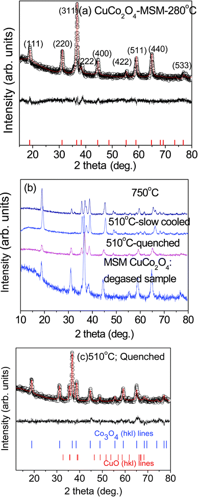 |
| | Fig. 1 XRD patterns: (a) the Rietveld refined XRD pattern and the lattice structure of CuCo2O4 prepared at 280 °C. The continuous line is fitted data and symbols are experimental data and the difference pattern are shown. Vertical lines are (hkl) lines. (b) XRD patterns of degassed CuCo2O4 and CuO·Co3O4 prepared at different temperatures. (hkl) lines and temperature are labelled. (c) The Rietveld refined XRD pattern of CuCo2O4 sample quenched at 510 °C. The miller indices (hkl) lines of Co3O4 and CuO phases are shown as vertical lines for clarity. | |
SEM images of CuCo2O4 prepared under different temperatures are shown in Fig. 2a–f. Particle sizes of the prepared samples range from 100–500 nm. As shown in the figures, CuCo2O4 prepared at 280 °C (Fig. 2a and b) and 750 °C (Fig. 2e and f) show an irregular cauliflower-like shape, and the sample prepared at 510 °C then quenched to room temperature (Fig. 2c and d) shows a regular cubic shape. BET surface areas of CuCo2O4 prepared at 280 °C and degassed, 510 °C-quenched, slow cooled and 750 °C are 9.8, 8.3, 3.0, 3.81 and 1.3 (±0.2) m2 g−1, respectively, and pore diameters of the samples range from 7.4–24 nm. We observed a clear trend in the BET surface area of the prepared samples as expected. That is, the surface area increases with a decrease in the preparation temperature. The HR-TEM images of CuCo2O4 prepared at 280 °C and 510 °C (quenched) are shown in Fig. 3a–h. The selected area electron diffraction (SAED) patterns in Fig. 3d–h show concentric rings composed of bright spots. The (hkl) lines (miller indices) according to d-spacing of different rings are also indicated in Fig. 3d and h and they match well with the XRD patterns of CuCo2O4 prepared at 280 °C and 510 °C (quenched), respectively.
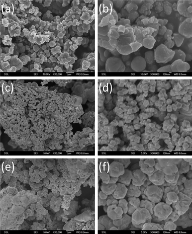 |
| | Fig. 2 SEM images of CuCo2O4 or CuO·Co3O4 composites under different temperatures. (a) 280 °C; 10K magnification; bar scale, 1 μm (b) 280 °C; 30 K magnification; bar scale, 100 nm, (c) 510 °C (quenched); 10 K magnification; bar scale, 1 μm, (d) 510 °C (quenched); 30K magnification; bar scale, 100 nm (e) 750 °C; 10 K magnification; bar scale, 1 μm (f) 750 °C; 30K magnification; bar scale, 100 nm. | |
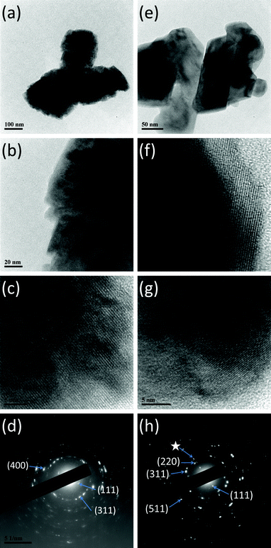 |
| | Fig. 3 HR-TEM images of CuCo2O4. (a) MSM-280 °C; bar scale, 100 nm, (b) MSM-280 °C; bar scale, 20 nm, (c) MSM-280 °C; bar scale, 5 nm, d-valve corresponds to (111) line, (d) MSM-280 °C; SAED pattern and (e) 510 °C (quenched); bar scale, 50 nm, (f) 510 °C (quenched); bar scale, 5 nm, d-values corresponds to Co3O4 (hkl) line, (g) 510 °C (quenched); bar scale, 5 nm, d-value corresponds to CuO (hkl) line, (h) 510 °C (quenched); SAED pattern (☆ CuO line) | |
Electrochemical studies
Galvanostatic cycling
In order to determine the electrochemical properties of the CuCo2O4, galvanostatic cycling of the fabricated cells was carried out. Li-cycling in the voltage range of 0.005–3.0 V vs. Li and the current rate of 60 mA g−1 are shown in Fig. 4a–f. Fig. 4a and b present the graphs of voltage versus capacity plots of Li/CuCo2O4 cells fabricated using samples prepared at MSM-280 °C and degassed, respectively, of selected cycles. For clarity, we selected the 1st and 2nd cycles of all of the compounds and they are shown separately in Fig. 4e and f, respectively. From galvanostatic cycling of CuCo2O4 prepared at 280 °C (Fig. 4a), we observed an intercalation region around 1.75 V, a structure destruction/amorphization at ∼1.35 V and a solid electrolyte interface (SEI) at low voltages (below 0.5 V) in the first discharge process. These features are common to most of the transition metal oxides undergoing conversion reactions.9 Cycling profiles of first charge process and subsequent cycles are different from that of the 1st discharge process (Fig. 4a and e). The 1st discharge capacity is 1237 (±10) mAh g−1 and the 1st charge capacity is 850(±5) mAh g−1, which gives an irreversible capacity loss of 390 mAh g−1 (about ∼31%). Our observed reversible capacity values are very close to theoretical capacity of 873 mAh g−1 (for 8 moles of Li). From the 2nd cycle onwards, it shows a capacity fading of ∼30% up to the 40th cycle and an average capacity loss of ∼7 mAh g−1 per cycle, as shown in Fig. 5. The 1st discharge–charge cycling profiles of MSM CuCo2O4-280 °C degassed sample at 200 °C are shown in Fig. 4b and they are almost similar to bare sample. Improved capacity values are noted with initial cycles (Table 1) and the capacity fading was 28% between 2–40 cycles.
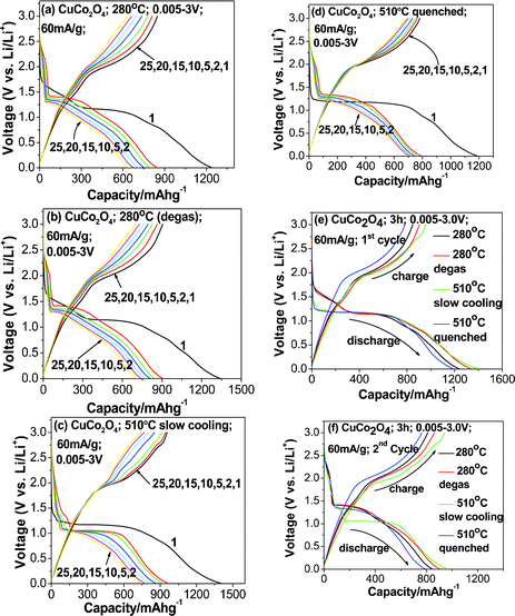 |
| | Fig. 4 Galvanostatic discharge–charge cycling curves of (a) CuCo2O4-280 °C, (b) CuCo2O4-280 °C (degassed at 200 °C in the presence of N2 gas), (c) CuCo2O4-510 °C (CuO·Co3O4), (c) slow cooling, (d) quenched, (e) 1st cycle plots of CuCo2O4-280 °C, CuCo2O4-280 °C (degassed at 200 °C), CuCo2O4-510 °C-quenched and slow cooling, (f) 2nd cycle plots of CuCo2O4-280 °C, CuCo2O4-280 °C (degassed at 200 °C), CuCo2O4-510 °C (CuO·Co3O4), quenched and slow cooling ; voltage window: 0.005–3.0 V, current rate: 60 mA g−1. | |
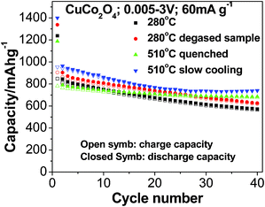 |
| | Fig. 5 Capacity vs. cycle number plots of CuCo2O4 prepared at 280 °C, CuCo2O4 280 °C (degassed at 200 °C), CuCo2O4 510 °C (slow cooling) (CuO·Co3O4) and CuCo2O4 510 °C (quenched) (CuO·Co3O4). Closed and open symbols correspond to discharge and charge capacity, respectively. Voltage range: 0.005–3.0 V, current rate: 60 mA g−1. | |
Table 1 Capacity values of CuCo2O4 prepared at different temperatures. Voltage range: 0.005–3.0 V, current rate: 60 mA g−1
| |
CuCo2O4 |
CuO.Co3O4 |
| Preparation temperature |
280 °C |
280 °C degassed |
510 °C quenched |
510 °C slow cooling |
| 1st discharge capacity (±20 mAh g−1) |
1238 |
1338 |
1187 |
1400 |
| 1st charge capacity (±10 mAh g−1) |
848 |
904 |
781 |
942 |
| 2nd charge capacity (±10 mAh g−1) |
810 |
863 |
764 |
930 |
| 40th charge capacity (±10 mAh g−1) |
565 |
619 |
678 |
742 |
| Capacity fading (2–40 cycles)% |
30 |
28 |
11 |
20 |
We proposed a reaction mechanism that is similar to previous studies reported by our group.16 We noticed an additional intercalation reaction around 1.75 V vs. Li:
| | | Cu2+Co3+2O4 + 8Li+ + 8e− ↔ LixCuCo2O4 → Cu + 2Co + 4Li2O | (1) |
| | | Cu + Li2O ↔ CuO + 2Li+ + 2e− | (2) |
| | | 2Co + 2Li2O ↔ 2 CoO+4Li+ +4e− | (3) |
| | | 2CoO + 2/3Li2O ↔ 2/3Co3O4 + 4/3Li + 4/3e− | (4) |
We can expect a reversible capacity corresponding to 6 mol of Li per mole of CuCo2O4 (eqn (2) and (3)) and in the most favourable case with the contribution from eqn (4), a capacity of 7.33 and 8.23 mol of Li for CuCo2O4 samples prepared at 280 °C and degassed samples, respectively. A slight excess capacity in the latter compound is due to differences in sample preparation or slight errors in the weight of the active material.
The voltage vs. capacity curves of (CuO·Co3O4 composites) prepared at 510 °C under slow cooled and quenched conditions are shown in Fig. 4c and d. We observed voltage plateaux at ∼1.25 V for all of the discharge curves, which is quite different from that sample prepared at 280 °C, especially in terms of the 1st discharge process. However, all of the charge curves are generally smooth. The discharge and charge capacity of 1st cycle are 1187 mAh g−1 and 780 mAh g−1, respectively (Fig. 4c, e and f). The 1st discharge–charge capacity vs. voltage profiles of the slow cooled sample prepared at 510 °C are shown in Fig. 4e and cycling profiles of the quenched sample are shown in (Fig. 4d,f). The 1st discharge profiles of samples prepared at 510 °C by slow cooling and quenching are almost similar (Fig. 4e), whereas slight differences in the 2nd discharge profiles are seen with Fig. 4f, which is partially due to more intense peaks of CuO lines, which are clearly reflected in the XRD pattern (Fig. 1b) and also due to differences in the crystal structure and surface area of the samples. The electrochemical mechanism of CuO and Co3O4 composites are similar to previous studies.8,9
The capacity vs. cycle number data of all compounds (CuCo2O4 and CuO·Co3O4) are shown in Fig. 5. For clarity, discharge–charge capacity and capacity fading values are summarized in Table 1. From the information above, the irreversible capacity loss that occurred during the 1st discharge–charge cycles CuCo2O4 prepared at 280 °C , 280 °C (degassed), 510 °C (quenched) and 510 °C (slow cooled) are 32%, 32%, 34% and 33%, and corresponding capacity fading from the 2nd to 40th cycles are 30%, 28%, 11% and 20%, respectively. From the above information, the samples prepared at 510 °C had higher and more stable capacity than those at 280 °C. It clearly indicates that composites of CuO·Co3O4 play an important role in Li-cycling as the higher preparation temperature could break CuCo2O4 into CuO and Co3O4 phases (Fig. 1b and c). Notably, 510 °C (slow cooling) sample had a high capacity of ∼750 (±10) mAh g−1 and stabilized from the 25th cycle, and the average capacity fading of 510 °C (quenched) sample in between the 2nd to 40th cycles is 2 mAh g−1 per cycle. Those results are close to and even better than the results reported by our group when using the urea combustion method (discharge and charge capacity at the 20th cycle; 755 (±10) and 745 (±10) mAh g−1, respectively, and average capacity fading of 2 mAh g−1 per cycle).16 Further improvement in capacity retention is possible by proper selection of molten salts.
Cyclic voltammetry
Cyclic voltammetry was carried out within the potential range of 0.005–3.0 V vs. Li/Li+ at a scan rate of 58 μV s−1. The results of cyclic voltammetry curves are shown in Fig. 6a–d. For clarity, only selected cycles are shown. During the first cathodic scan (for reduction refer to eqn (1)) there are sharp peaks that occur at 0.9–1.0 V with onsets at ∼1.25 V (Fig. 6a and b). The relatively weaker peak of the 280 °C sample as compared to the 280 °C degassed sample can be attributed to the presence of moisture in the sample or a variation of the surface oxidation state of metal oxides or a slight difference in the weight of active material. It is well-known that CV peak currents are sensitive to mass or thickness of the active material29 and annealing temperature.30 During the first anodic scan (for oxidation refer to forward reaction in eqn (2–4)), there are peaks at ∼2.1 V. From the second cycle onwards, the anodic peaks move to a higher potential of 2.1–2.2 V, and the cathodic peaks move to a higher potential of ∼1.1–1.2 V with onsets of ∼1.5 V. This indicates that after the structure destruction of CuCo2O4 in the first cycle, Cu and Co particles are formed (eqn (1)), and Cu and Co oxides are also formed during oxidation (forward reaction of eqn (2–4)). These oxides are being reduced at the second cycle and onwards (backward reaction of eqn (2–4)). The broad peaks in the second and subsequent cycles observed are due to structure destruction or amorphization of the crystal lattice. CV of subsequent cycles shows a slight change in potential and diminishing peak current intensity, which indicates the capacity fading of CuCo2O4. The main cathodic and anodic potentials fit well with the Co3O4 prepared by MSM24 and urea combustion method CuCo2O416 and slightly differs from alloying and conversion-based spinel oxide ZnCo2O4.25
 |
| | Fig. 6 Cyclic voltammetry studies (a) CuCo2O4-280 °C, (b) CuCo2O4-280 °C (degassed at 200 °C in N2 gas), (c) CuCo2O4 (CuO·Co3O4) composites prepared at 510 °C, (c) quenched and (d) slow cooling. Scan rate: 0.058 mV s−1, voltage window: 0.005–3.0 V vs. Li. Li-metal as a counter and reference electrode. | |
Minor additional peaks are seen with CuCo2O4 samples prepared at different temperatures by the molten salt method, which is due to differences in the reaction temperature, initial salts, preparation method and composite nature of the oxide materials. The main cathodic potentials of CuCo2O4-510 °C slow-cooled sample showed a peak around 0.92 V (Fig. 6d), which is similar to the peak obtained from galvanostatic cycling profiles (Fig. 4f). Additional minor peaks during cathodic and anodic scan arise from the CuO phase.9 Further detailed studies on the temperature dependence of molten salt synthesis and electrochemical studies of the properties of CuO are in progress.
Conclusions
We have successfully synthesized nano/submicron size CuCo2O4 and CuO·Co3O4 composites using MSM at different temperatures. Galvanostatic cycling of CuCo2O4 prepared at 510 °C at the current rate of 60 mA g−1 in the voltage range 0.005–3.0 V. At the end of the 40th cycle, it exhibits a reversible capacity of 700 (quenched) and 740 (slow cooling) (±5) mAh g−1 and an average capacity fading of around 2 mAh g−1. The average discharge/charge reaction plateau potential is ∼1.25 V and ∼2.0 V vs. Li/Li+. CV studies showed the main cathodic and anodic potentials at ∼1.2 V and ∼2.1 V. The performance of CuCo2O4 anode for LiBs could be further optimized further. In addition, CuCo2O4 could be used for other promising applications, like bifunctional electrocatalysts in fuel cell applications.
Acknowledgements
The authors thank National Research Foundation (NRF) Singapore NRF-CRP Grant No R-144-000-295-281 (“Novel 2D Materials with Tailored Properties: Beyond Graphene”) and also Grant No.: R-143-000-360-281 (Graphene Related Materials and Devices). Thanks to Ms Chong Ai Lin and Mr. Chiam Shier Yi from NUS High School and Faculty of Science for the grant WBS: N-144-000-005-001 (SCIENTIA 2011 project).
References
- M. J. Duncan, F. Leroux, J. M. Corbett and L. F. Nazar, J. Electrochem. Soc., 1998, 145, 3746–3757 CrossRef CAS.
- , K. E. Alifantis, S. A. Hackney and R. Vasant Kumar ed.High Energy density Lithium batteries: MaterialsEngineering, Applications, Wiley VCH, 2010 Search PubMed.
-
G.-A. Nazri and G. Pistoiaed.Lithium Batteries: Science and Technology, Kluwer Acad Publ., New York, USA., 2003 Search PubMed.
- D. Guyomard, C. Sigala, A. L. G. La Salle and S. Y. Piffard, J. Power Sources, 1997, 68, 692–697 CrossRef CAS.
- M. V. Reddy, B. Pecquenard, P. Vinatier and A. Levasseur, J. Phys. Chem. B, 2006, 110, 4301–4306 CrossRef CAS.
- M. V. Reddy, C. Wannek, B. Pecquenard, P. Vinatier and A. Levasseur, J. Power Sources, 2003, 119, 101–105 CrossRef.
- P. Poizot, S. Laruelle, S. Grugeon, L. Dupont and J. M. Tarascon, Nature, 2000, 407, 496–499 CrossRef CAS.
- J. Cabana, L. Monconduit, D. Larcher and M. R. Palacin, Adv. Mater., 2010, 22, E170–E192 CrossRef CAS.
- M. V. Reddy, G. V. Subba Rao and B. V. R. Chowdari, Chem. Rev., 2012 Search PubMed , revisions submitted.
- B. Das, M. V. Reddy, P. Malar, T. Osipowicz, G. V. Subba Rao and B. V. R. Chowdari, Solid State Ionics, 2009, 180, 1061–1068 CrossRef CAS.
- B. Das, M. V. Reddy and B. V. R. Chowdari, J. Mater. Chem., 2012, 22, 17505–17510 RSC.
- Y. Sharma, N. Sharma, G. V. Subba Rao and B. V. R. Chowdari, Adv. Funct. Mater., 2007, 17, 2855–2861 CrossRef CAS.
- R. Alcantara, M. Jaraba, P. Lavela and J. L. Tirado, Chem. Mater., 2002, 14, 2847–2848 CrossRef CAS.
- Y. Sharma, N. Sharma, G. V. Subba Rao and B. V. R. Chowdari, Solid State Ionics, 2008, 179, 587–597 CrossRef CAS.
- H. Kim, D. H. Seo, I. Park, J. Hong, K. Y. Park and K. Kang, Chem. Mater., 2012, 24, 720–725 CrossRef CAS.
- Y. Sharma, N. Sharma, G. V. Subba Rao and B. V. R. Chowdari, J. Power Sources, 2007, 173, 495–501 CrossRef CAS.
- P. Afanasiev and C. Geantet, Coord. Chem. Rev., 1998, 178, 1725–1752 CrossRef.
- M. V. Reddy, G. V. Subba Rao and B. V. R. Chowdari, J. Power Sources, 2006, 159, 263–267 CrossRef CAS.
- M. V. Reddy, G. V. Subba Rao and B. V. R. Chowdari, J. Phys. Chem. C, 2007, 111, 11712–11720 CAS.
- M. V. Reddy, G. V. Subba Rao and B. V. R. Chowdari, J. Power Sources, 2006, 160, 1369–1374 CrossRef CAS.
- X. Zhao, M. V. Reddy, H. X. Liu, S. Ramakrishna, G. V. Subba Rao and B. V. R. Chowdari, RSC Adv., 2012, 2, 7462–7469 RSC.
- Z. Peining, W. Yongzhi, M. V. Reddy, A. Sreekumaran Nair, P. Shengjie, N. Sharma, V. K. Peterson, B. V. R. Chowdari and S. Ramakrishna, RSC Adv., 2012, 2, 5123–5126 RSC.
- M. V. Reddy, B. D. Tung, L. Yang, N. D. Quang Minh, K. P. Loh and B. V. R. Chowdari, J. Power Sources, 2012 DOI:10.1016/j.jpowsour.2012.07.009.
- M. V. Reddy, Z. Beichen, L. J. Nicholette, Z. Kaimeng and B. V. R. Chowdari, Electrochem. Solid-State Lett., 2011, 14, A79–A82 CrossRef CAS.
- M. V. Reddy, K. Y. H. Kenrick, T. Y. Wei, G. Y. Chong, G. H. Leong and B. V. R. Chowdari, J. Electrochem. Soc., 2011, 158, A1423–A1430 CrossRef CAS.
- M. V. Reddy, G. V. Subba Rao and B. V. R. Chowdari, J. Mater. Chem., 2011, 21, 10003–10011 RSC.
- C. T. Cherian, J. Sundaramurthy, M. Kalaivani, P. Ragupathy, P. S. Kumar, V. Thavasi, M. V. Reddy, C. H. Sow, S. G. Mhaisalkar, S. Ramakrishna and B. V. R. Chowdari, J. Mater. Chem., 2012, 22, 12198–12204 RSC.
- A. Sakunthala, M. V. Reddy, S. Selvasekarapandian, B. V. R. Chowdari and P. C. Selvin, Energy Environ. Sci., 2011, 4, 1712–1725 CAS.
- M. V. Reddy, B. Pecquenard, P. Vinatier and A. Levasseur, Electrochem. Commun., 2007, 9, 409–415 CrossRef CAS.
- M. V. Reddy, B. Pecquenard, P. Vinatier and A. Levasseur, J. Power Sources, 2007, 163, 1040–1046 CrossRef CAS.
|
| This journal is © The Royal Society of Chemistry 2012 |
Click here to see how this site uses Cookies. View our privacy policy here.