Effects of SiO2 and P2O5 on structural, thermal and conductivity properties of inorganic materials doped with PVDF
Uma
Thanganathan
*a and
Masayuki
Nogami
b
aResearch Core for Interdisciplinary Sciences (RCIS), Okayama University, Tsushima-Naka Kita-Ku, Okayama, 700-8530, Japan. E-mail: umthan09@cc.okayama-u.ac.jp; Fax: +81 86 251 8705; Tel: +81 86 251 8706
bDepartment of Materials Science and Engineering, Nagoya Institute of Technology, Showa, Nagoya, 466-8555, Japan
First published on 15th August 2012
Abstract
Poly(vinylidene fluoride) (PVDF) doped hybrid glass membranes were prepared with various concentrations of tetraethoxysilane (TEOS), trimethylphosphate and PVDF. The proton conductivities of composites were measured at room temperature under dry conditions. The significant properties of these membranes were their thermal stability, up to 350 °C, and mechanical stability. These properties are adequate for the usage of the membranes in low and intermediate fuel cells. The objective of this work was to improve the conductivity and stability of a class of hybrid composites through optimization of the inorganic compounds and PVDF. The composites were examined using various analytical techniques: XRD, FTIR, ATR, TGA, DSC, proton conductivity and SEM. The H2/O2 fuel cells with the hybrid glass membrane show a maximum current density of about 320 mA cm−2 under the conditions of 60 and 80 °C with a relative humidity of 100%. The results were discussed and compared with the commercially available membranes for fuel cells.
1. Introduction
Proton exchange membrane fuel cells (PEMFCs) are receiving special attention as practical fuel cell candidates because of their low and high operating temperatures, low emissions, and suitability for use in portable electronics, electric vehicles, and stationary applications. The research work was focused on increasing the power density, reducing costs, and improving the reliability and durability of the PEMFCs. In this regard, we considered development of more efficient proton-conducting electrolytes as an effective way to improve the performance of fuel cells. The proton-conducting membrane used in PEMFC systems should be an electrical insulator and a good conductor for hydrogen ions (protons).1,2The most common and established types of membranes are the perfluorinated membranes, of which Nafion is a typical example.3 Nafion and related perfluorinated polymers are still the favorite electrolyte membranes for fuel cells applications in power sources for electric vehicles, in stationary applications, and in portable electronics. Despite having favorable properties, these perfluorinated membranes are not yet ideal because they have a few important drawbacks, such as high cost, low thermal stability, and low selectivity for the fuel permeability. Many attempts have been made to synthesize modified perfluorinated systems with improved thermal stability combined with high conductivity and low cost,3,4 but with limited success. Therefore, different and new concept approaches must be sought to obtain alternative types of proton-conducting membranes. One promising area of development is low cost non-fluorinated systems with high proton conductivity.
Many researchers have diverted their interest to the development of alternative proton-conducting membranes that can work at elevated temperatures or low humidity (dry) conditions.5–8 A partially fluorinated polymer electrolyte membrane is an interesting candidate for replacing Nafion® because of its easy preparation, good power, desirable methanol permeability and low costs along to the electrochemical properties comparable to the perfluorinated membranes.9–15 Moreover, partially fluorinated polymer electrolyte membranes possess unique properties, such as low surface energy, high chemical and thermal stabilities, and good mechanical properties.
Poly(vinylidene fluoride) (PVDF) [–CH2CF2–]n is a fluoro-polymer with a similar chemical structure to polyethylene, in which two hydrogen atoms are replaced by fluorine atoms. It is a chemically resistant polymer with good mechanical strength. PVDF is one of the most extensively used membrane materials in industry for its outstanding oxidation stability, superior thermal and hydrolytic stabilities, as well as good mechanical and membrane forming properties. However, its hydrophobic nature, which often results in severe membrane fouling, and impermeability have been barriers for their applications in water treatment.16 Many studies have been performed to improve the hydrophilicity of PVDF membranes by various methods, such as physical blending, chemical grafting, and surface modification.17 In this work, PVDF was chosen as a partially fluorinated polymer because of its lower cost compared to a fully fluorinated polymer, and sufficient resistance against the conditions in a fuel or electrolysis cell.
A combination of porous oxide materials, as hosts, and organic polymers, as guests, offers interesting possibilities for new types of hybrid materials. These materials need improvement of their mechanical stability for applications as hybrid materials. An inorganic network can be formed in the blend around the polymer, and a sol–gel process can be performed on the organic polymer solutions. In this case, two extremes of composite membranes could be observed; one in which an inorganic proton conductor acts as the only proton conducting element and is suspended in a non-interacting inert support, such as PVDF; or one in which a super-acidic inorganic proton conductor is intimately mixed with a strongly interacting ionomer to create a hybrid composite.
Some years ago, the preparation of hybrid organic–inorganic composites18–20 attracted much attention because such hybrids may provide controllable properties, such as optical, electrical, and mechanical behaviors, by combining the properties of both the organic polymer and inorganic compounds.21,22 Hybrid systems are usually prepared through a sol–gel process by incorporating organic polymers with alkoxysilanes, mainly tetramethoxysilane or tetraethoxysilane (TEOS). Hybrids of PVDF with SiO2 have been investigated for applications in electronic devices with a charge storage effect and electro-active stability23 because better electronic properties could be developed without losing the crystallization characteristics of the polymers.
Preparation and characterization of PVDF copolymers and SiO2 hybrids have been reported.24 Ciuffa et al.25 reported the ionic conductivity properties of membranes comprising of PVDF/SiO2/EC/PC/H3PO4 for applications in non-conventional polymer electrolyte fuel cells. In a similar way, other polymer hosts, like poly(silamine),26 poly(benzimidazole),27 and poly(methyl methacrylate)28 have also been explored. Croce et al.29 reported the ionic conductivity and current–voltage characteristics of copoly(vinylidene fluoride-chlorotrifluoroethylene) with dispersed ceramic filler. So far, to the best of our knowledge no attempt has been made on copoly(vinylidene fluoride-hexafluoropropylene) based membranes that possess amorphous domains capable of trapping large amounts of liquid electrolytes and crystalline phases with sufficient mechanical strength for the processing of free-standing films.
Nogami et al. reported the sol–gel preparation of inorganic glass membranes with a conductivity of ∼10 mS cm−1 at room temperature30,31. The conductivity of P2O5/SiO2 glass was ∼10 mS cm−1, ten times larger than that of the SiO2 glass, which is comparable to that of Nafion. The hybrid membrane heated to 200 °C exhibited a conductivity of ∼60 mS cm−1, approximately six times larger than that of the Nafion. The obtained hybrid membrane showed good thermal stability and mechanical flexibility, and was expected to find application as the electrolyte membrane in fuel cells.32 Using a sol–gel method, we succeeded in the preparation of P2O5-containing glasses exhibiting conductivities of 10−4 to 10−2 S cm−1 at room temperature.33,34 The POH strong hydrogen bonds with water molecules are appropriate for increasing the proton conduction, while the SiO2 is useful to increase the mechanical strength of the glass.
This paper reports the preparation of a class of hybrid glass membrane based on PVDF and SiO2/P2O5via sol–gel technique, and their characterizations by XRD, FTIR, TGA, and SEM techniques, and proton conductivity. To the best of our knowledge, no attempt has been made on the SiO2/P2O5/PVDF hybrid glass membranes that possess amorphous electrolytes with sufficient mechanical strength, thermal stability, and high proton conductivity. A schematic representation of the hybrid organic–inorganic composite membrane is presented in Fig. 1.
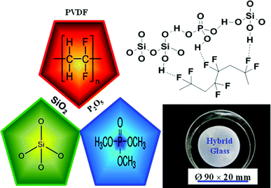 | ||
| Fig. 1 A profile of the SiO2/P2O5/PVDF hybrid glass composite membrane. | ||
2. Experimental
2.1. Preparation of hybrid glass composite membrane
Preparation of the hybrid glass composite membrane was conducted in few steps (Fig. 2) for three systems (A, B, and C). Here we explain for one sample (A-(a) 70/15/15 wt%). In the first step, a particular amount of PVDF (15 wt%) with a melt viscosity of 28,000–34,000 poise (Polyscience Inc.) was dissolved in dimethyl formamide (5 mL) (DMF, Nacalai, Japan) using a magnetic stirrer at 60 °C for 1 h. After dissolving, the transparent solution was cooled to room temperature. Next, TEOS (70 wt%), (Si(OC2H5)4, of 99.9% pure (Colcote, Japan) was hydrolyzed with ethanol and water in the presence of HCl (C2H5OH![[thin space (1/6-em)]](https://www.rsc.org/images/entities/char_2009.gif) :
:![[thin space (1/6-em)]](https://www.rsc.org/images/entities/char_2009.gif) H2O of 1
H2O of 1![[thin space (1/6-em)]](https://www.rsc.org/images/entities/char_2009.gif) :
:![[thin space (1/6-em)]](https://www.rsc.org/images/entities/char_2009.gif) 5 1 M HCl) using a stirrer at room temperature. Then, trimethylphosphate (15 wt%) (Nacalai Tesque, Japan) was added dropwise to the solution. The mixture was stirred for 1 day at 60 °C to become a viscous transparent solution. The resultant solution was poured into Petri dishes (φ 90 × 20 mm) and kept in closed drawers for few weeks to dry. The dried membranes were treated (twice) with water at 150 °C (Electric Drying Oven-DRN 620DB, Japan) for 24 h and heated at 600 °C (in a dry oven) for 6 h to get a glass product. The thickness of the transparent hybrid glass membrane was 0.5–1 mm (Fig. 1). Following a similar method, we prepared hybrid glass membranes by changing the chemical compositions of PVDF (10, 20, 30 wt%), SiO2 (65, 75, 85 wt%), and P2O5 (5, 10, 25 wt%). In the sol–gel process, for the preparation of the glass membranes, to reduce the stress of the glass membranes, the room atmosphere of the gelation process was kept saturated with water vapor.
5 1 M HCl) using a stirrer at room temperature. Then, trimethylphosphate (15 wt%) (Nacalai Tesque, Japan) was added dropwise to the solution. The mixture was stirred for 1 day at 60 °C to become a viscous transparent solution. The resultant solution was poured into Petri dishes (φ 90 × 20 mm) and kept in closed drawers for few weeks to dry. The dried membranes were treated (twice) with water at 150 °C (Electric Drying Oven-DRN 620DB, Japan) for 24 h and heated at 600 °C (in a dry oven) for 6 h to get a glass product. The thickness of the transparent hybrid glass membrane was 0.5–1 mm (Fig. 1). Following a similar method, we prepared hybrid glass membranes by changing the chemical compositions of PVDF (10, 20, 30 wt%), SiO2 (65, 75, 85 wt%), and P2O5 (5, 10, 25 wt%). In the sol–gel process, for the preparation of the glass membranes, to reduce the stress of the glass membranes, the room atmosphere of the gelation process was kept saturated with water vapor.
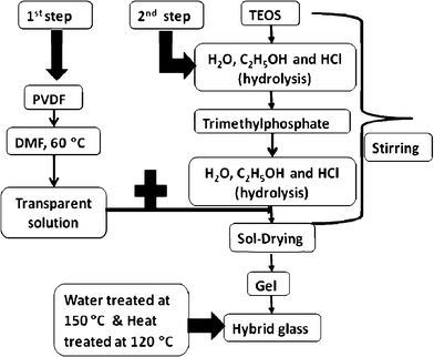 | ||
| Fig. 2 Preparation method for the SiO2/P2O5/PVDF hybrid glass composite membrane. | ||
In preparation of the membrane electrode assembly (MEA) with an active geometric area of 1 cm2, Pt/C electrodes were symmetrically deposited on both sides of the membrane with a loading of 0.2 mg cm−2. The polarization measurements were carried out using a Gas Supply System model RFC-1500 fuel cell test station. The gases were allowed to pass through stainless steel humidifiers before entering the fuel cell inlets, and the flow rates (20–80 mL min−1) were controlled using mass flow controllers. Pure hydrogen and oxygen gases were supplied, respectively, to the anode and cathode sides of the single cell.
2.2. Characterization techniques
For all the characterizations, we ground glass pieces using a planetary ball mill (Pulverisette 7, Fritsch) to obtain fine powders. X-ray powder diffraction patterns were recorded at room temperature using a Rigaku Multiflex X-ray diffractometer (Cu-Kα radiation, 2 kV/20 mA at a scan rate of 2° min−1). The diffraction patterns were recorded from 10 to 60° 2θ.Fourier transform infrared spectroscopy (FTIR) of the hybrid membranes were recorded between 4000 and 450 cm−1 using a JASCO FTIR-460 spectrometer. A minimum of 25 scans was signal averaged with a resolution of 4 cm−1 in the 4000–450 cm−1 range. Attenuated total reflectance FTIR (ATR-FTIR) spectroscopy examination was conducted in the 4000–600 cm−1 range using a JASCO FTIR-4100 spectrometer. Spectra were recorded using 25 scans at 4 cm−1 resolution.
The thermal stabilities were examined using a thermogravimetry analyzer (TGA) (Perkin-Elmer, DTG-50) performing under a dry nitrogen atmosphere over a temperature range of 30 to 600 °C at a heating rate of 10 °C min−1. The samples were ground into fine powder and heated at 60 °C in an oven for 1 h before starting the measurements. The measurements were performed on 3–5 mg samples. The relationship between the weight loss and temperature was recorded.
The proton conductivities were determined using a complex impedance method at room temperature under dry conditions. The samples were glass pieces. The active region (2Φ) selected on the surface of the glasses were coated with gold sputtering. The impedance measurements were carried out on a Solartron SI 1260 impedance/gain phase analyzer over the frequency range from 1 Hz to 1 MHz with a voltage amplitude of 10 mV. Samples thicknesses and widths were accurately measured using a Mitutoyo digital micrometer and calipers, respectively. Morphologies of the membranes were examined using a Hitachi S-2600H scanning electron microscope (SEM).
3. Results and discussion
3.1. XRD measurements
XRD analyses patterns for the SiO2/P2O5/PVDF hybrid glass composite membranes are shown in Fig. 3. The XRD patterns of the three kinds of composites (A, B, and C) with various ratios of the concentrations of SiO2, P2O5, and PVDF revealed that larger amounts of SiO2 increase the amorphous phase of all the composites. Peaks at 2θ = 18.3°, 20° and 26.6° correspond to the crystalline peaks of PVDF.35 The larger proportion of the inorganic component mixed with the crystalline polymer led to the phase changes in the hybrid matrix, which was confirmed by the appearance of a non-crystalline phase. The XRD pattern of pure PVDF (Fig. 3D) shows it as a semicrystalline polymer with several peaks centered at diffraction angles of 2θ = 18.2°, 20.2°, 26.5°, 32°, 35°, and 39°, referring to the diffractions in planes of (020), (021), and (002), respectively, all characteristic of the PVDF α phase.36,37 In addition, both of the patterns show a weak peak at 2θ = 20.2°, referring to the sum of the diffractions in planes (110) and (200), characteristic of the PVDF β phase. However, the peaks at 2θ = 20.2° and 39° are characteristics of the PVDF β and α phases respectively. The semicrystalline polymer incorporated with the inorganic SiO2, produced a molecular structure and physical network in the backbone of the hybrids, leading to a decrease in the crystalline peaks and an increase in the broad amorphous peak at 2θ = 23° for all the hybrid glass composite membranes. The intensities of the crystalline peaks further decreased, indicating the more amorphous type morphology of the composite membranes. The dynamic result was a “sol” composed of the hydrolyzed and condensed species that would eventually grow into a percolating network or gel.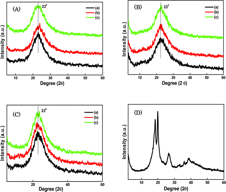 | ||
| Fig. 3 XRD curves for the SiO2/P2O5/PVDF hybrid glass composite membranes: A-(a) 70/15/15 wt%, (b) 70/10/20 wt% and (c) 70/5/25 wt%; B-(a) 85/5/10 wt%, (b) 75/5/20 wt% and (c) 65/5/30 wt%; C-(a) 85/5/10 wt%, (b) 75/15/10 wt% and (c) 65/25/10 wt%; D- pure PVDF. | ||
3.2. FTIR examinations
Infrared absorption spectra of SiO2/P2O5/PVDF hybrid composite glass membranes are shown in Fig. 4. FTIR spectroscopy was used to study the chemical structures of the hybrid composites containing various proportions of PVDF, SiO2, and P2O5. For the spectra of the samples, the main peaks at approximately 529, 840, 1479, 1645, 2436, and 2821 cm−1 wave numbers were observed (Fig. 4A). In this case, the concentration of SiO2 was constant and the amounts of P2O5 and PVDF were varied. In Fig. 4B, peaks at 563, 827, 982, 1487, 1632, 2446, and 2803 cm−1 were displayed for the hybrid glass composite containing a constant amount of P2O5 with the varied amounts of SiO2 and PVDF. The peaks were observed at 511, 793, 1329, 1473, 1664, 2433, and 2768 cm−1 in Fig. 4C, for samples with constant PVDF concentration. The peaks in the same wave number ranges confirm the formation of a composite in the hybrid glass network. The peak found at approximately 3600 cm−1, appearing as the strongest peak in Fig. 4A, B and C spectra, should be related to the chemical species derived from water, such as H3O+, in addition to water. The varied amounts of the three compounds in the hybrid matrix were subjected to the same treatments in the spectral region of interest. It was observed that the irradiation caused only minor spectral changes for all the composites. The weak bands at approximately 1645, 1632, and 1664 cm−1, were the characteristic features of the structural changes created in the hybrid network. The absorption band at 1150 cm−1 became prominent, which was due to the formation of Si–O–Si.38,39 The broad peak indicates that a significant number of O–H groups were left. These O–H groups provided the sites for the hydrogen bonding between PVDF and SiO2, resulting in a homogenous glass. The peak at 1050 cm−1, which corresponds to the –CF2– stretching vibration, decreased after the addition of the inorganic particles. The coordination and the interaction of the SiO2 with PVDF may reduce the peak intensity to give amorphous structure to the hybrid glass composites. These FTIR spectroscopic results strongly support the successful bridge formation of the organic backbone with the inorganic matrix and sol–gel reaction of polymer with TEOS.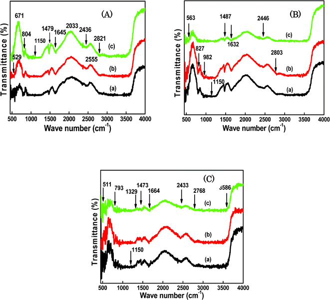 | ||
| Fig. 4 FTIR curves for the SiO2/P2O5/PVDF hybrid glass composite membranes: A-(a) 70/15/15 wt%, (b) 70/10/20 wt% and (c) 70/5/25 wt%; B-(a) 85/5/10 wt%, (b) 75/5/20 wt% and (c) 65/5/30 wt%; C-(a) 85/5/10 wt%, (b) 75/15/10 wt% and (c) 65/25/10 wt%. | ||
ATR-FTIR measurements were carried out in the range from 600 to 4000 cm−1 for all the hybrid glass composite membranes. The absorption spectra in Fig. 5 are characterized by a broad band at approximately 1000–1200 and 800 cm−1, indicating the presence of an extensive network structure of Si–O–Si groups. Furthermore, the bands at 1500 and 1650 cm−1 are assigned to stretching modes of the P![[double bond, length as m-dash]](https://www.rsc.org/images/entities/char_e001.gif) O and O
O and O![[double bond, length as m-dash]](https://www.rsc.org/images/entities/char_e001.gif) P–OH, respectively. The POH bonds are appropriate to increase the proton conduction, because of their strong hydrogen bonding with water molecules. In Fig. 5A, the main peaks at 783, 923, 1079, 1588, 2370, and 2921 cm−1 were observed and the strong absorption peaks at 775, 781, 965, 1080, 1587, and 2368 cm−1 were obtained in Fig. 5B. Similar peaks were observed at 789, 1065, 2335 and 2921 cm−1 in Fig. 5C. Overall observations reveal that the spectra of the hybrid glass composites contain peaks at wave numbers ranging from 700 to 1500 cm−1, which correspond to vinylidene, –CF3 groups, –CH2 wagging of the vinylidene band, out-of-plane C–H bending, –C–F– stretching, CF2 stretching, and scissoring vibration of the vinyl group.40,41
P–OH, respectively. The POH bonds are appropriate to increase the proton conduction, because of their strong hydrogen bonding with water molecules. In Fig. 5A, the main peaks at 783, 923, 1079, 1588, 2370, and 2921 cm−1 were observed and the strong absorption peaks at 775, 781, 965, 1080, 1587, and 2368 cm−1 were obtained in Fig. 5B. Similar peaks were observed at 789, 1065, 2335 and 2921 cm−1 in Fig. 5C. Overall observations reveal that the spectra of the hybrid glass composites contain peaks at wave numbers ranging from 700 to 1500 cm−1, which correspond to vinylidene, –CF3 groups, –CH2 wagging of the vinylidene band, out-of-plane C–H bending, –C–F– stretching, CF2 stretching, and scissoring vibration of the vinyl group.40,41
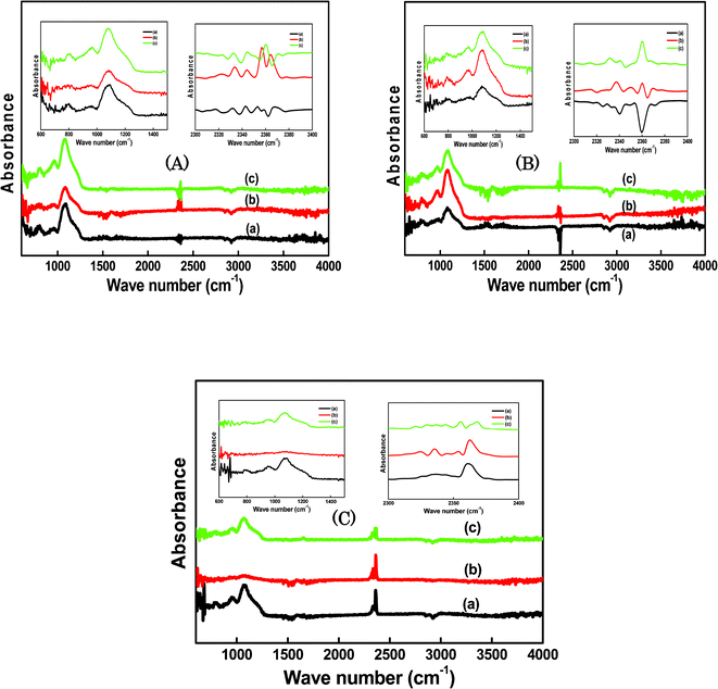 | ||
| Fig. 5 ATR spectra for the SiO2/P2O5/PVDF hybrid glass composite membrane: A-(a) 70/15/15 wt%, (b) 70/10/20 wt% and (c) 70/5/25 wt%; B-(a) 85/5/10 wt%, (b) 75/5/20 wt% and (c) 65/5/30 wt%; C-(a) 85/5/10 wt%, (b) 75/15/10 wt% and (c) 65/25/10 wt%. | ||
The spectra in the wave number ranges of 600–1500 cm−1 and 2300–2400 cm−1 are elaborated inside the Fig. 5A–C. The absorption bands peaks at ∼3600 cm−1 and ∼2921 cm−1 were observed in all composites, which both are assigned to the OH stretching. The positions of the OH absorption bands depend on the degree of the hydrogen bonding strength; they shift to smaller wave numbers with increasing the strength of the hydrogen bonding.42 Among the absorption bands, the band at 3600 cm−1 is assigned to the hydrogen-bonding of free SiOH bonds. On the other hand, the bands at 2921 cm−1, which were observed in the glasses containing P2O5 and their intensities increased with increasing the P2O5 content, are assigned to the POH bonds. The phosphorus ions are bound with the silica network consisting of the core structure. Therefore, pore surfaces of the obtained glasses are rich in POH groups. The proton in the POH group is strongly hydrogen bonded to the water molecules compared with that of the SiOH groups. Upon hydrolysis of the inorganic glass matrix with PVDF, the absorption band at 1080 cm−1 was clearly observed in the hybrid composites. The absorption bands at 600–1500 cm−1, mostly in all composites, correspond to the α phase of PVDF. The vibrational spectra of the three principal phases (α, β, and γ) of PVDF have been extensively investigated.43
3.3. Thermal stability
The TGA measurements were performed to characterize the thermal stabilities of the SiO2/P2O5/PVDF hybrid glass composite membranes. Generally, the thermal stabilities of the membranes are improved with the addition of SiO2. As shown in Fig. 6, all the hybrid glass composites showed good thermal stabilities up to 200 °C. For these hybrid glass composites, a three-step degradation pattern was observed. TGA curves show two weight losses from 50 °C to 380 °C. In Fig. 6A(a–c), the first weight loss (0.5–12.6%) started at 50 °C to 100 °C, which was mostly due to the loss of adsorbed water incorporated during sol–gel process. Continuous weight losses (17.2–14.7%) were measured up to 200–220 °C, presumably related to the thermal degradation of alkoxides in gels that completely hydrolyzed in the hybrid composites. Compared with Si–OH, the proton in the POH group was strongly attached to water molecules through hydrogen bonding, resulting in a higher temperature necessary to remove the water from POH. The third weight losses of 26.1–23.1% at 370–390 °C are indications of the decomposition of the polymer backbone. Similarly in Fig. 6B, we observed three weight losses at the same temperature ranges; the first ones of 1.6% and 12.6% up to 49–160 °C, the second one of 14.5% at approximately 200 °C, and the third one of 24.9% at 330 °C. In Fig. 6C, the TGA curves display the first weight losses from 0.9% to 10.1% at 45 and 105 °C, the second ones of 17.2% and 19.1% at 200–230 °C, and the third ones of 29.7% at 400 °C. The TGA curve in Fig. 6C(a) shows that, as the temperature rose from room temperature, a gradual weight loss occurred from 230 to 400 °C. That is, the residue weight of the composite at 400 °C increased with the increasing of the TEOS content. Based on this observation, the amounts of SiO2 formed in the composites can be determined. This result suggests that the sol–gel reaction and the introduction of SiO2 to PVDF clearly enhance the thermal stability of the hybrid composite membranes.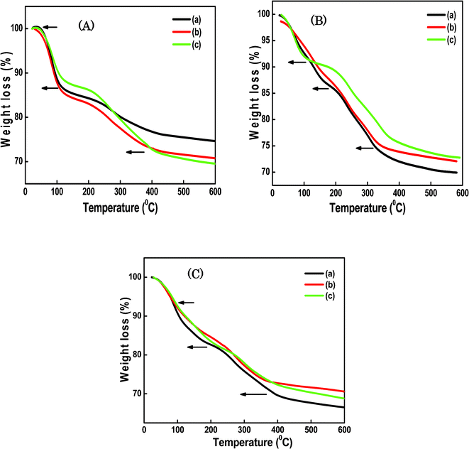 | ||
| Fig. 6 TGA curves for the SiO2/P2O5/PVDF hybrid glass composite membranes: A-(a) 70/15/15 wt%, (b) 70/10/20 wt% and (c) 70/5/25 wt%; B-(a) 85/5/10 wt%, (b) 75/5/20 wt% and (c) 65/5/30 wt%; C-(a) 85/5/10 wt%, (b) 75/15/10 wt% and (c) 65/25/10 wt%. | ||
3.4. Proton conductivity examinations
The proton conductivities of the hybrid glass composite membranes were determined at room temperature (Fig. 7). All the optimized SiO2/P2O5/PVDF hybrid composites exhibited conductivity values of 10−2 S cm−1 at room temperature. The conductivity values of 7.8, 6.3 and 9.5 × 10⁻² S cm−1 were found for SiO2/P2O5/PVDF hybrid glass composite membranes with molar ratios of 70/15/15, 85/5/10 and 65/25/10 wt%, respectively at room temperature. In comparison to Nafion, the conductivity of the hybrid glass composite membrane was quite large at low temperatures.44,45 However, it was comparable to that of the largest conductivity at room temperature, which was achieved by the P2O5–SiO2 glass electrolyte.46 The present conductivity values were compared with similar hybrid membranes for fuel cells, and the obtained values were larger than the reported values.47,48 These results reveal that the proton conductivities of the glass membranes increased with the increase in P2O5 content (20%) in the composite. The proton conductivity decreased with the increase of the TEOS concentration because the SiO2 nanoparticles did not contribute to the proton conduction. Proton conduction is associated with the proton hopping between hydroxyl groups and water molecules. Generally, the phosphate compounds are lacking in chemical durability and the absorbed water lowers the chemical stability of the glasses, despite the possibility of high conductivities. It is necessary to elucidate the effects of P2O5 content and adsorbed water on the proton conductivity for the development of the practical high-conducting glasses.49,50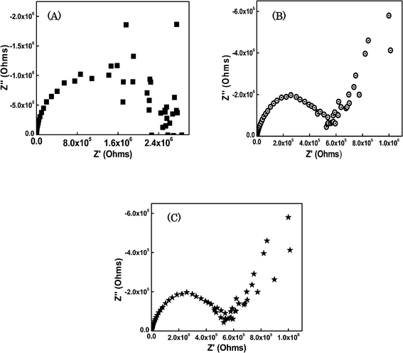 | ||
| Fig. 7 Conductivity of the SiO2/P2O5/PVDF hybrid glass composite membranes: (A) 70/15/15 wt%, (B) 85/5/10 wt% and (C) 65/25/10 wt%. | ||
The conductivity mechanism of these gel-type membranes is substantially different from that occurring in Nafion-type systems, where the presence of water is vital for assisting the proton transport. Two proton transport mechanisms exist in such membranes: (1) surface transport in which the protons are hopping on the surface of the pore channels, and (2) bulk transport in which the protons are hopping in the bulk of the pore channels. For the pore channels in an aqueous medium, protons can transport in different forms, such as H3O+ in the surface transport mechanism, and H5O2+ as well as H9O4+ in the case of the bulk transport mechanism.51–53 The sol–gel-derived hybrid glass membranes surfaces are terminated with hydroxyl bonds and absorb water in a humid atmosphere. The proposed mechanism for proton conduction in these glasses is the dissociation of protons from hydroxyl bonds and the proton hopping between hydroxyls and water molecules.
We have already reported the conductivity of SiO2/P2O5 glass as ∼10 mS cm−1, ten times larger than that of the SiO2 glass, which is comparable to that of Nafion.32 The pores sizes of Nafion and SiO2/P2O5 were approximately 5 nm and 2.8 nm, respectively. Nevertheless, it is easy to understand that the P2O5/SiO2 glasses exhibit much larger conductivities compared with SiO2 glasses.31 The present P2O5/SiO2 glass was prepared through reacting P2O5 with the hydrolyzed TEOS, where the phosphorus ions were bound to the silica network which is the core structure. Therefore, the POH bonds, which are preferred for proton conduction, are selectively bonded to the pore surface. Generally, the polymer does not affect the increase of the conductivity but contributes in the improvement of the chemical and mechanical stability. The conductivity values for PVDF-based proton-conducting membranes without SiO2 and P2O5 was 0.1 S cm−1 at 25 °C.54,55 Moreover, the results of the studies on the conductivity of the SiO2/P2O5/PVDF hybrid glass composite membranes at various temperatures and humidity conditions will be reported in the near future.
3.5. Morphology characterization
The surface morphology of the SiO2/P2O5/PVDF hybrid composite glass membranes were characterized using the SEM technique at various magnifications. Micrographs in Fig. 8 show that the hybrid systems were well homogeneously mixed via a sol–gel process and the organic polymer crystalline phase disappeared in the hybrid network. Results also showed that the interactions between PVDF and SiO2/P2O5 mainly happened at the surface of the hybrid glass composite, whereas interactions between SiO2 and PVDF mainly occurred in the amorphous phase. By the incorporation of the inorganic particles to the polymer matrix, the morphology of the composites showed a continuous phase structure with well-mixed homogeneous particles at the microscale level. Furthermore, the SiO2 particles and crystalline PVDF phases were not observed in the micrographs of the hybrid composites and no aggregation of SiO2 particles was observed, which means that SiO2 particles were homogeneously dispersed in the PVDF matrix. The reason could be the formation of a cross-linked structure of the SiO2 particles with polymeric chains after the sol–gel process.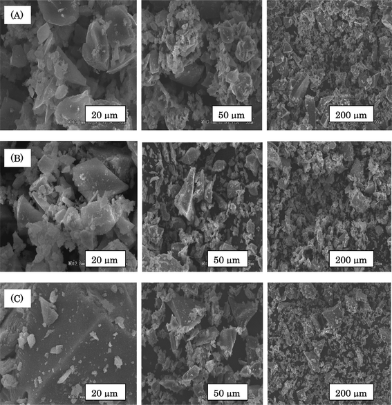 | ||
| Fig. 8 SEM images for the SiO2/P2O5/PVDF hybrid glass composite membranes: A-(a) 70/15/15 wt%, (b) 70/10/20 wt% and (c) 70/5/25 wt%; B-(a) 85/5/10 wt%, (b) 75/5/20 wt% and (c) 65/5/30 wt%; C-(a) 85/5/10 wt%, (b) 75/15/10 wt% and (c) 65/25/10 wt%. | ||
3.6. I–V profile
The polarization curves of the H2/O2 fuel were operated at 60 and 80 °C with humidification at 100% RH using MEA consisting of the SiO2/P2O5/PVDF (70/15/15 wt%) hybrid glass composite membrane and Pt/C electrodes are shown in Fig. 9. The active area of the cell was 1 cm2 and operation occurred under a feed of hydrogen and oxygen at the anode and cathode sides, respectively, at 1 atm pressure. The current density obtained was 320 mA cm−2 at a cell voltage of 0.98 V with a controlled cell temperature at 60 and 80 °C in the fabrication process. The performance strongly depends on the MEA preparation conditions. At low catalyst loading of 0.2 mg cm−2 Pt/C for both anode and cathode sides, and using air atmosphere, the single-cell performance with the hybrid membrane showed a high open circuit voltage of 0.98 V and a maximum current density of 320 mA cm−2. This value is larger than the reported value for similar hybrid membranes used for the fuel cell.56,57 But this result was smaller than standard commercial Nafion membranes.58,59 Then, we may conclude that the application of thin composite membranes to the H2/O2 system is effective to obtain a high performance. Such a study should help optimize the membrane electrode assembly.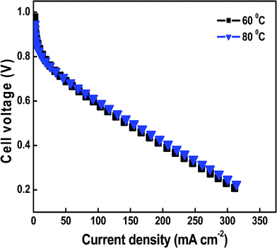 | ||
| Fig. 9 The polarization curves for H2/O2 fuel cells operating at 60 and 80 °C using MEAs containing SiO2/P2O5/PVDF (70/15/15 wt%) hybrid glass composite membranes as the electrolyte. | ||
4. Conclusions
In this work, hybrid glass composite membranes, prepared via sol–gel reaction, exhibited a high proton conductivity at room temperature and good thermal stability. XRD and FTIR spectroscopy examinations displayed amorphous phases and absorption peaks related to the Si–O–Si and Si–OH groups. This study confirmed that the interactions between SiO2, P2O5 and PVDF, form a porous structure and reduce the glass transition temperature and crystallinity, increasing the proton conductivity of the hybrid glass composites. The SEM micrographs clearly showed a homogeneous and smooth surface for the hybrid membranes. The larger amounts of SiO2 in the hybrid composites produced glasses with less flexibility. The cell performance of the membrane was displayed by a current density of about 320 mA cm−2 at 60 and 80 °C.We used the hybrid composite membrane and performed the fuel cell test at low temperatures. The performance was comparable to similar hybrid membrane performances at similar operating conditions.
In the next step, the amount of TEOS will be reduced to prepare composite film samples with high conductivity for the fuel cell applications.
Acknowledgements
We are grateful for the financial support by the Ministry of Education, Sport, Culture, Science and Technology (MEXT) and the Special Coordination Funds for Promoting Sciences and Technology of Japan. We thank Prof. Kishimoto, Graduate School of Natural Science of Technology and Prof. Kimura, Graduate School of Environmental Science, Okayama University, Japan, to allow us to use their laboratory equipment.References
- K. Kordesch and G. Simader, Fuel Cells and their Applications, VCH Verlagsgesellschaft, Germany, 1996 Search PubMed.
- P. Colomban, Ann. Chim. Sci. Mater., 1999, 24, 1–18 CrossRef CAS.
- O. Savadogo, J. New Mat. Elect. Syst., 1998, 1, 47–66 CAS.
- M. K. Daletoua, J. K. Kallitsis, G. Voyiatzis and S. G. Neophytides, J. Membr. Sci., 2009, 326, 76–83 CrossRef.
- D. K. Lee, J. T. Park, D. K. Roh, B. R. Min and J. H. Kim, Macromol. Res., 2009, 17, 325–331 CrossRef CAS.
- J. Reiter, J. Velicka and M. Mika, Electrochim. Acta, 2008, 53, 7769–7774 CrossRef CAS.
- D. S. Kim, M. D. Guiver, M. Y. Seo, H. I. Cho, D. H. Kim, J. W. Rhim, G. Y. Moon and S. Y. Nam, Macromol. Res., 2007, 15, 412–417 CrossRef CAS.
- Y. Yang, Z. Shi and S. Holdcroft, Eur. Polym. J., 2004, 40, 531–541 CrossRef CAS.
- S. Holmberg, P. Holmlund, R. Nicolas, C. E. Wilen, T. Kallio, G. Sundholm and F. Sundholm, Macromolecules, 2004, 37, 9909–9915 CrossRef CAS.
- Y. Shen, X. Qiu, J. Shen, J. Xi and W. Zhu, J. Power Sources, 2006, 161, 54–60 CrossRef CAS.
- Y. W. Kim, D. K. Lee, K. J. Lee and J. H. Kim, Eur. Polym. J., 2008, 44, 932–939 CrossRef CAS.
- M. Shen, S. Roy, J. W. Kuhlmann, K. Scott, K. Lovell and J. A. Horsfall, J. Membr. Sci., 2005, 151, 121–130 CrossRef.
- M. M. Nasef, N. A. Zubir, A. F. Ismail, M. Khayet, K. Z. M. Dahlan, H. Saidi, R. Rohani, T. I. S. Ngah and N. A. J. Sulaiman, J. Membr. Sci., 2006, 268, 96–108 CrossRef CAS.
- Y. Shen, X. Qiu, J. Shen, J. Xi and W. Zhu, J. Power Sources, 2006, 161, 54–60 CrossRef CAS.
- P. Costamagna and S. Srinivasan, J. Power Sources, 2001, 102, 253–269 CrossRef CAS.
- W. Z. Lang, Z. L. Xu and H. Yang, J. Membr. Sci., 2007, 288, 123–131 CrossRef CAS.
- Y. Lu, S. L. Yu and B. X. Chai, J. Membr. Sci., 2006, 276, 162–167 CrossRef.
- U. Schubert, N. Husing and A. Lorenz, Chem. Mater., 1995, 7, 2010–2027 CrossRef CAS.
- P. Judeinstein and C. Sanchez, J. Mater. Chem., 1996, 6, 511–525 RSC.
- J. Wen and G. Wilkes, Chem. Mater., 1996, 8, 1667–1681 CrossRef CAS.
- K. G. Neoh, K. K. Tan, P. L. Goh, S. W. Huang, E. T. Kang and K. L. Tan, Polymer, 1999, 40, 887–893 CrossRef CAS.
- Y. Imai, K. Naka and Y. Chujo, Macromolecules, 1998, 31, 532–534 CrossRef CAS.
- D. Yang and W. Bei, Conference Record of the 1996 IEEE International Symposium on Electrical Insulation, Montreal, Canada, 16–19 June, 1996, p. 854 Search PubMed.
- J. W. Cho and K. I. Sul, Polymer, 2001, 42, 727–736 CrossRef.
- F. Ciuffa, F. Croce, A. D. Epifacino, S. Panero and B. Scrosati, J. Power Sources, 2004, 127, 53–57 CrossRef CAS.
- K. Surukara, M. Rikukawa, K. Sanui, N. Ogata, Y. Nagasaki and M. Kato, Electrochim. Acta, 2000, 45, 1391–1394 CrossRef.
- M. Kawahara, J. Morita, M. Rikukawa, K. Sanui and N. Ogata, Electrochim. Acta, 2000, 45, 1395–1398 CrossRef CAS.
- A. M. Stephan and K. S. Nahm, Polymer, 2006, 47, 5952–5964 CrossRef CAS.
- F. Croce, J. Hassoun, C. Tizzani and B. Scrosati, Electrochem. Commun., 2006, 8, 1125–1131 CrossRef CAS.
- M. Nogami, H. Matsushita, Y. Goto and T. Kasuga, Adv. Mater., 2000, 12, 1370–1372 CrossRef CAS.
- M. Nogami, R. Nagao, C. Wong, T. Kasuga and T. Hayakawa, J. Phys. Chem. B, 1999, 103, 9468–9472 CrossRef CAS.
- M. Nogami, Y. Usui and T. Kasuga, Fuel Cells, 2001, 1, 181–185 CrossRef CAS.
- M. Nogami and Y. Abe, Appl. Phys. Lett., 1997, 71, 1323–1325 CrossRef CAS.
- M. Nogami, H. Matsushita, T. Kasuga and T. Hayakawa, Electrochem. Solid-State Lett., 1999, 2, 415–417 CrossRef CAS.
- M. Caillon-Cavanier, B. Claude-Montigny, D. Lemordant and G. Bosser, J. Power Sources, 2002, 107, 125–132 CrossRef.
- G. T. Davis, J. E. McKinney, M. G. Broadhurst and S. C. Roth, J. Appl. Phys., 1978, 49, 4998–5002 CrossRef CAS.
- R. Jr. Gregorio and M. Cestari, J. Polym. Sci., Part B: Polym. Phys., 1994, 32, 859 CrossRef.
- H. L. Tang and M. Pan, J. Phys. Chem. C, 2008, 112, 11556–11568 CAS.
- H. Hagihara, H. Uchida and M. Watanabe, Electrochim. Acta, 2006, 51, 3979–3985 CrossRef CAS.
- P. Mustarelli, E. Quartarone, C. Capiglia, C. Tomasi, P. Ferloni and A. Magistris, J. Chem. Phys., 1999, 111, 3761–3768 CrossRef CAS.
- F. Croce, G. P. Appetecchi, S. Slane, M. Salomon, M. Tavarez, S. Arumugam, Y. Wang and S. G. Greenbaum, Solid State Ionics, 1996, 86–88, 307–312 CrossRef CAS.
- H. Scholze, Glastech. Ber, 1959, 32, 81–88, 1959, 32, 142–152, 1959, 32, 314–420 Search PubMed.
- R. Jr. Gregorio, J. Appl. Polym. Sci., 2006, 100, 3272–3279 CrossRef.
- J. J. Sumner, S. E. Creager, J. J. Ma and D. D. DeMarteau, J. Electrochem. Soc., 1998, 145, 107–110 CrossRef CAS.
- R. T. C. Slade, A. Hardwick and P. G. Dickens, Solid State Ionics, 1983, 9–10, 1093–1098 CrossRef CAS.
- M. Nogami, R. Nagao, C. Wong, T. Kasuga and T. Hayakawa, J. Phys. Chem. B, 1999, 103, 9468–9472 CrossRef CAS.
- D. A. Boysen, C. R. I. Chisholm, S. M. Haile and S. R. Narayananb, J. Electrochem. Soc., 2000, 147, 3610–3613 CrossRef CAS.
- S. J. Huang, H. K. Lee, Y. S. Lee and W. H. Kangw, J. Am. Ceram. Soc., 2005, 88, 3427–3432 CrossRef CAS.
- M. Nogami, M. Miyamura and Y. Abe, J. Electrochem. Soc., 1997, 144, 2175–2178 CrossRef CAS.
- M. Nogami and Y. Abe, Appl. Phys. Lett., 1997, 71, 1323–1325 CrossRef CAS.
- M. Eikerling, A. A. Kornyshev, A. M. Kuznetsov, J. Ulstrup and S. Walbran, J. Phys. Chem. B, 2001, 105, 3646–3662 CrossRef CAS.
- E. Spohr, P. Commer and A. A. Kornyshev, J. Phys. Chem. B, 2002, 106, 10560–10569 CrossRef CAS.
- A. A. Kornyshev, A. M. Kuznetsov, E. Spohr and J. Ulstrup, J. Phys. Chem. B, 2003, 107, 3351–3366 CrossRef CAS.
- T. Lehtinen, G. Sundholm, S. Holmberg, F. Sundholm, P. Björnbom and M. Bursell, Electrochim. Acta, 1998, 43, 1881–1890 CrossRef CAS.
- M. A. Navarra, S. Panero and B. Scrosati, J. Solid State Electrochem., 2004, 8, 804–808 CrossRef CAS.
- M. Helen, B. Viswanathan and S. S. Murthy, J. Power Sources, 2006, 163, 433–439 CrossRef CAS.
- F. Pereira, K. Vallé, P. Belleville, A. Morin, S. Lambert and C. Sanchez, Chem. Mater., 2008, 20, 1710–1718 CrossRef CAS.
- D. H. Peck, Y. G. Chun, C. S. Kim, D. H. Jung and D. R. Shin, J. New Materials for Electrochem. Systs., 1999, 2, 121–124 CAS.
- S. Litster and G. McLean, J. Power Sources, 2004, 130, 61–70 CrossRef CAS.
| This journal is © The Royal Society of Chemistry 2012 |
