Microplasma arrays: a new approach for maskless and localized patterning of materials surfaces†‡
Endre J.
Szili§
a,
Sameer A.
Al-Bataineh§
a,
Paul
Ruschitzka
a,
Gilles
Desmet
a,
Craig
Priest
b,
Hans J.
Griesser
b,
Nicolas H.
Voelcker
c,
Frances J.
Harding
c,
David A.
Steele
a and
Robert D.
Short
*a
aMawson Institute, University of South Australia, Mawson Lakes, SA 5095, Australia. E-mail: rob.short@unisa.edu.au; Fax: +61 8 8302 5639; Tel: +61 8 8302 5629
bIan Wark Research Institute, University of South Australia, Mawson Lakes, SA 5095, Australia
cFlinders University, School of Chemical and Physical Sciences, Bedford Park, SA 5042, Australia
First published on 9th October 2012
Abstract
“Maskless” microplasma treatment of passivated surfaces has been developed for the micropatterning of materials surfaces. The micropatterned surfaces are used in the fabrication of arrays for protein and cell-based assays. The advantage of this micropatterning approach is that it can be easily integrated into current manufacturing practices and the resultant micropatterned surfaces used with existing life sciences techniques and instrumentation.
Introduction
The surface patterning of materials is a common element in new and emerging technologies. Current methods rely upon direct contact with the material or physical masks, which significantly restricts the potential for scale-up. Surface-bound biomolecules are used in multiplex surface-capture assays providing hundreds to thousands of data points per experiment.1 Biomolecule patterns are fabricated by a variety of methods including micro-contact printing,2 micro-spotting,3 hydrogel stamping,4 chemical vapour deposition5–8 and pin-printing,9 or alternatively by “on-chip” biomolecule synthesis.10 Printing is distinctly different to solution immobilization: small, nanolitre drops evaporate very fast. Proteins may denature, aggregate or change conformation. Non-uniform drying and blocking present further complications. Spatially controlled binding of proteins onto three-dimensional surfaces or enclosed structures such as microfluidic channels presents additional challenges.11Technological plasma, comprising an electrically-excited ionized gas, is typically operated at low pressure in a large enclosed chamber with a volume of several litres. Non-equilibrium between high-temperature electrons and the remaining plasma components enables their use in surface engineering of materials by modification or deposition without altering the properties of the bulk material.12,13 Plasma has been exploited to chemically pattern surfaces14 or create protein “adhesive” patches on non-fouling backgrounds.15,16 However, application of plasma patterning has been restricted by the requirements of a physical mask or photolithography. Atmospheric pressure microplasmas retain many of the properties of large volume plasmas but are geometrically confined to small dimensions. Microplasma designs, properties and potential applications have been described elsewhere.17–25 Microplasma devices have been developed for localized surface modification using a method referred to as “plasma printing”.26–29 Discrete high-resolution chemical modification is achieved by intimate contact between the substrate and the plasma stamp.
We describe the localized, non-contact patterning of open and enclosed surfaces by microplasma arrays. Patterned surfaces form the platform for biomolecules and cell assays. Our method involves the complete uniform passivation of a surface and the use of a microplasma array to produce the spatially controlled removal (and/or modification) of the passivating agent on open and enclosed surfaces. The result is islands of spatially defined adhesivity, onto which biomolecules or cells may be bound. This patterning method is robust, versatile and non-contact; it negates the need for physical masks or additional photolithographic steps, can be easily scaled up for large scale industrial processes and eliminates environmentally harmful organic chemicals.
Results and discussion
Fig. 1a,b shows a photograph of the device used and an optical micrograph of part of the array, respectively. Fig. 1c shows the array ignited at 760 Torr in helium. Each cavity ignites discretely with similar output, affording an array of spatially separated micro-compartments for the heterogeneous chemical modification of surfaces.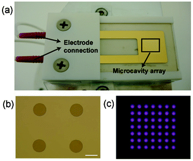 | ||
| Fig. 1 (a) Photograph of the microcavity plasma array device, (b) optical micrograph of part of the array and (c) the microplasma array ignited at 1 kVpeak–peak and 10 kHz in helium at 760 Torr. Scale bar = 250 μm. | ||
Passivation of a polystyrene surface by adsorption of bovine serum albumin (BSA) conferred resistance to subsequent protein adsorption. To demonstrate the effects of regioselective surface modification, BSA passivated polystyrene surfaces were treated with the microplasma array for 10 s at a distance of 150 μm, followed by incubation with a fluorescently-labelled streptavidin protein. Fig. 2a,b shows the contrast in the resulting fluorescence microscopy images between regions directly exposed to the microplasma cavities and the surrounding area. Streptavidin selectively attached to the regions modified by the microplasma generating a microarray of protein.
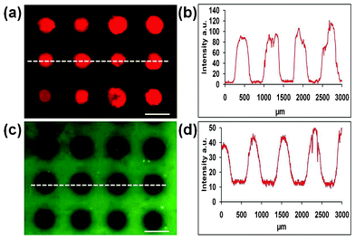 | ||
| Fig. 2 (a) Fluorescence micrograph of fluorescently-labelled streptavidin adsorbed onto BSA-passivated polystyrene after microplasma array treatment. (b) Corresponding fluorescence intensity profile across a section of the array, as indicated by the dashed white line in (a). (c) Fluorescence micrograph of fluorescently-labelled albumin attached to modified polystyrene after microplasma array treatment. (d) Corresponding fluorescence intensity profile across a section of the array, as indicated by the dashed white line in (c). Scale bars = 500 μm. | ||
The fluorescence of an adsorbed layer of fluorescently-labelled BSA on polystyrene after microplasma array treatment was significantly reduced in the regions directly exposed to the microplasma cavities (Fig. 2c,d). Post-treatment, each treated area displayed the same level of residual fluorescence (Fig. 2d). This is taken to indicate (i) constant luminosity across the microplasma array, and (ii) that each microplasma source within the array both removes and modifies material (complete removal would result in no residual fluorescence). The fluorescence signal did not recover even after 1 month, ruling out the possibility of photobleaching of the fluorophore.
Static time-of-flight secondary ion mass spectrometry (ToF-SIMS) was used to image BSA distribution post microplasma exposure. In corroboration with the fluorescence data, a positive fragment ion (C4H8N+, 70.070 amu) characteristic of BSA, revealed that the protein was (largely, but not completely) removed in the regions directly exposed to the plasma cavities (Fig. 3a).
 | ||
| Fig. 3 ToF-SIMS images of BSA-passivated polystyrene surfaces treated with the microplasma array. (a) An image of BSA-derived fragment ion C4H8N+, (b) an image of polystyrene-derived fragment ion C7H7+and (c) and an overlay image of BSA-derived (red) and polystyrene-derived (green) fragments in (a) and (b), respectively. Scale bar = 1 mm. | ||
A positive fragment ion (C7H7+, 91.055 amu) characteristic of the underlying polystyrene substrate30 was mapped as shown in Fig. 3b. From this it can be seen that there was a higher intensity of “polystyrene-type” fragments emanating from the plasma-exposed regions, compared to the background. This effect is more evident when overlaying the polystyrene and BSA images (Fig. 3c) and from statistical analysis (analysis of means) in the ESI†, Fig. S1.
We also pursued the application of microplasma array fabrication technology in enzyme immunoassays. Here, horseradish peroxidase (HRP) was regioselectively adsorbed to a microplasma-patterned BSA surface to mimic the format of an immunoblot assay. This surface was then incubated with a precipitating formulation of 3,3′,5,5′-tetramethylbenzidine (TMB). The localized HRP enzyme catalyzed the oxidation of soluble and colourless TMB into a dark blue insoluble product that precipitated over the enzyme-containing regions. The bright-field micrograph (taken in TMB) in Fig. 4 shows four distinct dark blue regions of precipitation caused by the HRP-catalyzed oxidation of TMB.
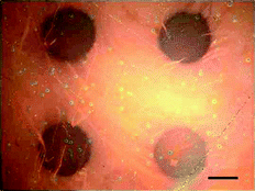 | ||
| Fig. 4 Bright-field microscopy image of a portion of an HRP enzyme array on a microplasma-treated BSA surface after incubation with TMB substrate. Scale bar = 200 μm. | ||
An inverse image of fluorescently-labelled streptavidin in Fig. 2a could be prepared by microplasma array treatment of pristine polystyrene (i.e. not blocked with BSA) (ESI†, Fig. S2a). The protein selectively adsorbed to the hydrophobic untreated polystyrene background in comparison to the hydrophilic (microplasma treated) spots within the array (ESI†, Fig. S2b). The microplasma patterning method was also successfully applied to glass microscope slides (ESI†, Fig. S3).
Fig. 5a,b shows the potential of this technology for protein sensing. A micropatterned surface was functionalised with a green fluorescent protein (GFP). GFP was only captured on the antibody functionalised surface.
 | ||
| Fig. 5 Immunorecognition on a BSA passivated polystyrene sample after microplasma array treatment. GFP capture was detected on the sample functionalized with anti-GFP (a) but was not detected on the microplasma array patterned sample containing no antibody (b). Scale bar = 500 μm. | ||
Whilst there are many alternative methods for the micropatterning of open material surfaces, few alternative methods allow for the patterning of enclosed surfaces.26,31–35 To demonstrate this capability, protein was locally adsorbed to specific regions along the length of a glass microchannel (Fig. 6a) following BSA-passivation. A fuller description of the microfluidic chip has been provided elsewhere11 and experimental details can be found in the ESI†. Fig. 6b shows the ignition of two adjacent microplasmas, which are used to “locally” remove BSA from the side walls of the microcapillary. Fluorescently-labelled streptavidin selectively bound to the areas that were exposed to the plasma (Fig. 6c).
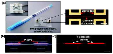 | ||
| Fig. 6 Integrated microplasma/microfluidic chip for surface patterning of bonded microchannels. (a) Photograph of the device next to a standard-sized pen for comparison; an optical micrograph section of the electrode/microchannel assembly on the right; and (inset) the assembled chip ready for operation. (b) Optical micrograph of localized plasma generation inside the microchannel during operation in helium. (c) Fluorescence micrograph of a microplasma-patterned microchannel after incubation with fluorescently-labelled streptavidin. Scale bars = 250 μm. | ||
Finally, we demonstrate that this technology can be used to create cell microarrays of attachment-dependent cell lines, such as those commonly used for drug screening.36 Specific cell attachment to microplasma-treated regions was observed for both SK-N-SH (human neuroblastoma line) cells (Fig. 7a) and HeLa (human epithelial carcinoma line derived from cervical cancer) cells (data not shown). Cell attachment to the BSA-passivated background was minimal. Over 48 h, a multi-layer of SK-N-SH cells developed within each spot of the microarray, indicative of normal behaviour for this cell line (Fig. 7b,c).37 Application of such arrays can be envisaged for screening protocols, such as identification of drug targets, where a moderate number of experimental replicates are required.
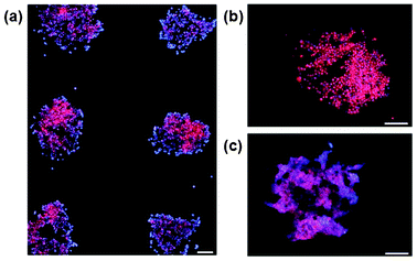 | ||
| Fig. 7 Localized cell attachment and proliferation on microplasma patterned surfaces. Cells are stained with Hoescht 33342 (blue, nuclear) and Cell Tracker Orange (red, cytoplasmic) dyes. Arrays are shown at 4, 24 and 48 h after cell seeding (panels a, b and c, respectively). Scale bars = (a) 250 μm and (b, c) 50 μm. | ||
In summary, this paper describes the use of microplasma arrays for fabrication of protein or cell microarrays on planar (e.g. silicon, glass, polystyrene) or 3D materials surfaces (e.g. side walls of microchannels). The microplasma sources were fabricated utilising straightforward optical lithographic methods, could be integrated into microfluidic chips with no extra processing steps, or alternatively can be fabricated at very low cost with no specialised equipment.38 The patterning technology is based on localised microplasma treatment of BSA. BSA is partially removed and modified creating islands of adhesivity for the subsequent binding of protein and cells. Feature size is limited by the design and technical issues associated with the microfabrication process and the physics for achieving stable microplasma operation; elsewhere a lateral feature size as small as 500 nm has been demonstrated.39 The interaction of plasmas with organic surfaces has been extensively studied with low pressure plasmas40 and more recently with atmospheric microplasmas.41,42 Based upon this literature and the experimental data in Fig. 2 and 3, we speculate that the inert gas plasma treatment of BSA is dominated by three concurrent processes involving oxidation, cross-linking and etching of the protein layer.
Conclusions
This paper described a straightforward and versatile method for patterning passivated materials surfaces utilizing non-contact microplasmas. Patterned surfaces provide the platform on which to bind proteins, antibodies, enzymes and cells. Protein solution binding resulted in uniform protein deposition (within each spot). The potential for this method is in the fabrication of low-density microarrays on chips or within microchannels, with high fidelity in feature fabrication arising from the localized nature of the plasma.Experimental section
Full experimental details giving sample preparation, treatment and analysis are in the ESI†. Detailed description of the microplasma array fabrication and operation is provided elsewhere.43Acknowledgements
This work was supported by the Australian International Science Linkage Project CG120119 and the Premier Science Research Fund. The authors acknowledge the facilities, and scientific and technical assistance of the Australian Microscopy & Microanalysis Research Facility at the South Australian Regional Facility. Microplasma array devices were fabricated at the University of South Australia node of the Australian National Fabrication Facility under the National Collaborative Research Infrastructure Strategy. We thank Doug Veale (Cantech) for the design and construction of the microplasma reactor.References
- P. Wu, D. G. Castner and D. W. Grainger, J. Biomater. Sci., Polym. Ed., 2008, 19, 725–753 CrossRef CAS.
- J. P. Renault, A. Bernard, A. Bietsch, B. Michel, H. R. Bosshard, E. Delamarche, M. Kreiter, B. Hecht and U. P. Wild, J. Phys. Chem. B, 2003, 107, 703–711 CrossRef CAS.
- J. S. Shumaker-Parry, M. H. Zareie, R. T. Aebersold and C. T. Campbell, Anal. Chem., 2004, 76, 918–929 CrossRef CAS.
- M. Mayer, J. Yang, I. Gitlin, D. H. Gracias and G. M. Whitesides, Proteomics, 2004, 4, 2366–2376 CrossRef CAS.
- H.-Y. Chen and J. Lahann, Adv. Mater., 2007, 19, 3801–3808 CrossRef CAS.
- H.-Y. Chen and J. Lahann, Langmuir, 2011, 27, 34–48 CrossRef CAS.
- H.-Y. Chen, J. H. Lai, X. Jiang and J. Lahann, Adv. Mater., 2008, 20, 3474–3480 CrossRef CAS.
- K. M. Vaeth and K. F. Jensen, Adv. Mater., 1999, 11, 814–820 CrossRef CAS.
- J. L. DeRisi, V. R. Iyer and P. O. Brown, Science, 1997, 278, 680–686 CrossRef CAS.
- D. Gerhold, T. Rushmore and C. T. Caskey, Trends Biochem. Sci., 1999, 24, 168–173 CrossRef CAS.
- C. Priest, P. J. Gruner, E. J. Szili, S. A. Al-Bataineh, J. W. Bradley, J. Ralston, D. A. Steele and R. D. Short, Lab Chip, 2010, 11, 541–544 RSC.
- R. M. France and R. D. Short, Langmuir, 1998, 14, 4827–4835 CrossRef CAS.
- E. J. Szili, S. Kumar, R. S. C. Smart, R. Lowe, E. Saiz and N. H. Voelcker, Surf. Sci., 2008, 602, 2402–2411 CrossRef CAS.
- L. Dai, H. J. Griesser and A. W. H. Mau, J. Phys. Chem. B, 1997, 101, 9548–9554 CrossRef CAS.
- B. W. Muir, A. Fairbrother, T. R. Gengenbach, F. Rovere, M. A. Abdo, K. M. McLean and P. G. Hartley, Adv. Mater., 2006, 18, 3079–3082 CrossRef CAS.
- S. S. Shah, M. C. Howland, L. Chen, J. Silangcruz, S. V. Verkhoturov, E. A. Schweikert, A. N. Parikh and A. Revzin, ACS Appl. Mater. Interfaces, 2009, 1, 2592–2601 CAS.
- K. H. Becker, K. H. Schoenbach and J. G. Eden, J. Phys. D: Appl. Phys., 2006, 39, R55–R70 CrossRef CAS.
- R. Foest, M. Schmidt and K. Becker, Int. J. Mass Spectrom., 2006, 248, 87–102 CrossRef CAS.
- F. Iza, G. J. Kim, S. M. Lee, J. K. Lee, J. L. Walsh, Y. T. Zhang and M. G. Kong, Plasma Processes Polym., 2008, 5, 322–344 CrossRef CAS.
- J. G. Eden, S. J. Park, N. P. Ostrom, S. T. McCain, C. J. Wagner, B. A. Vojak, J. Chen, C. Liu, P. von Allmen, F. Zenhausern, D. J. Sadler, C. Jensen, D. L. Wilcox and J. J. Ewing, J. Phys. D: Appl. Phys., 2003, 36, 2869–2877 CrossRef CAS.
- R. M. Sankaran and K. P. Giapis, J. Phys. D: Appl. Phys., 2003, 36, 2914–2921 CrossRef CAS.
- J. G. Eden, S. J. Park, N. P. Ostrom and K. F. Chen, J. Phys. D: Appl. Phys., 2005, 38, 1644–1648 CrossRef CAS.
- V. Karanassios, Spectrochim. Acta, Part B, 2004, 59, 909–928 CrossRef.
- G. Fridman, G. Friedman, A. Gutsol, A. B. Shekhter, V. N. Vasilets and A. Fridman, Plasma Processes Polym., 2008, 5, 503–533 CrossRef CAS.
- M. G. Kong, G. Kroesen, G. Morfill, T. Nosenko, T. Shimizu, J. van Dijk and J. L. Zimmermann, New J. Phys., 2009, 11, 115012 CrossRef.
- C.-P. Klages, A. Hinze, K. Lachmann, C. Berger, J. Borris, M. Eichler, M. von Hausen, A. Zänker and M. Thomas, Plasma Processes Polym., 2007, 4, 208–218 CrossRef CAS.
- S. Kreitz, C. Penache, M. Thomas and C. P. Klages, Surf. Coat. Technol., 2005, 200, 676–679 CrossRef CAS.
- A. Hinze, C.-P. Klages, A. Zänker, M. Thomas, T. Wirth and W. E. S. Unger, Plasma Processes Polym., 2008, 5, 460–470 CrossRef CAS.
- A. Möbius, D. Elbick, E.-R. Weidlich, K. Feldmann, F. Schüßler, J. Borris, M. Thomas, A. Zänker and C.-P. Klages, Electrochim. Acta, 2009, 54, 2473–2477 CrossRef.
- J. Davies, C. S. Nunnerley, A. C. Brisley, R. F. Sunderland, J. C. Edwards, P. Krüger, R. Knes, A. J. Paul and H. Hibbert, Colloids Surf., A, 2000, 174, 287–295 CrossRef CAS.
- C. Priest, Biomicrofluidics, 2010, 4, 032206 CrossRef.
- K. Kuribayashi, Y. Tsuda, H. Nakamura and S. Takeuchi, Sens. Actuators, B, 2010, 149, 177–183 CrossRef.
- T. Vong, J. ter Maat, T. A. van Beek, B. van Lagen, M. Giesbers, J. C. M. van Hest and H. Zuilhof, Langmuir, 2009, 25, 13952–13958 CrossRef CAS.
- M. A. Holden, S.-Y. Jung and P. S. Cremer, Anal. Chem., 2004, 76, 1838–1843 CrossRef CAS.
- C.-P. Klages, C. Berger, M. Eichler and M. Thomas, Contrib. Plasma Phys., 2007, 47, 49–56 CrossRef CAS.
- A. L. Hook, H. Thissen and N. H. Voelcker, Trends Biotechnol., 2006, 24, 471–477 CrossRef CAS.
- J. L. Biedler, L. Helson and B. A. Spengler, Cancer Res., 1973, 33, 2643 CAS.
- S. A. Al-Bataineh, E. J. Szili, A. Mishra, S.-J. Park, G. J. Eden, H. J. Griesser, N. H. Voelcker, R. D. Short and D. A. Steele, Plasma Processes Polym., 2011, 8, 695–700 CrossRef CAS.
- R. Kakei, A. Ogino, F. Iwata and M. Nagatsu, Thin Solid Films, 2010, 518, 3457–3460 CrossRef CAS.
- R. M. France and R. D. Short, J. Chem. Soc., Faraday Trans., 1997, 93, 3173–3178 RSC.
- P. M. Bryant, E. J. Szili, T. Whittle, S.-J. Park, J. G. Eden, S. Al-Bataineh, D. A. Steele, R. D. Short and J. W. Bradley, Surf. Coat. Technol., 2010, 204, 2279–2288 CrossRef CAS.
- E. J. Szili, S. A. Al-Bataineh, P. M. Bryant, R. D. Short, J. W. Bradley and D. A. Steele, Plasma Processes Polym., 2011, 8, 38–50 CrossRef CAS.
- S. A. Al-Bataineh, E. J. Szili, P. J. Gruner, C. Priest, H. J. Griesser, N. H. Voelcker, R. D. Short and D. A. Steele, Plasma Processes Polym., 2012, 9, 638–646 CrossRef CAS.
Footnotes |
| † Electronic Supplementary Information (ESI) available: Experimental details and supporting figures. See DOI:10.1039/c2ra21504g |
| ‡ Current address for Voelcker and Harding: Mawson Institute, University of South Australia. |
| § Szili and Al-Bataineh contributed equally to this work. |
| This journal is © The Royal Society of Chemistry 2012 |
