Modeling the interaction of convex solidifying interfaces with spherical particles
E.
Agaliotis
*ab,
M. R.
Rosenberger
ab,
A. E.
Ares
ab and
C. E.
Schvezov
ab
aCONICET (Consejo Nacional de Investigaciones Científicas y Técnicas), Rivadavia 1917, (1033) Buenos Aires, Argentina
bProg. Materiales, Modelización y Metrología, FCEQyN, Universidad Nacional de Misiones, Azara 1552, (3300) Posadas, Misiones, Argentina. E-mail: eliana@fceqyn.unam.edu.ar
First published on 3rd October 2012
Abstract
The phenomenon of pushing during solidification is modeled for the case of particles producing a convex interface. The thermal and fluid fields generated by the particle–melt–solid system are calculated in a decoupled way determining in the first place the shape of the interface and then, the two main forces acting during pushing; the drag and repulsion forces. The thermal and fluid flow fields were calculated using finite element methods. Both, the drag and repulsion forces are integrated at each step and compared until both are equal and the steady state of pushing is reached. The repulsion force is integrated using the Casimir–Lifshitz–Van der Waals interaction. The model predicts the equilibrium distance in a steady state of pushing for spherical particles and a convex solidifying interface. It is shown that the equilibrium separation distance for a convex interface results in a larger solidification velocity for trapping with respect to an ideal planar interface. The model results were in good agreement with experimental results for the critical velocity reported in the literature.
A Introduction
Solidification studies of materials containing particles have shown an interaction between the particle and the solid–liquid interface. In some systems it is observed as the segregation of the particles which is normally attributed to the mechanism of pushing. The phenomenon of pushing has been investigated experimentally and by mathematical modeling for many years;1–28 the experiments show that there is a critical velocity at which the particle cannot be pushed and as a result, the particle is trapped. The process is complex due to the variety of phenomena involved during pushing and associated with the fluid and thermal fields and the nature of the pushing force. In all cases, the physical problem depends on the properties, nature, and morphology of the interacting media; the particle, melt and solid; and the external fields such as gravity, thermal and electromagnetic fields.13–28For instance, in the case of different thermal conductivities for the particle and the solidifying material, it has been shown that the interface adopts planar or curved shapes10 as shown in Fig. 1.
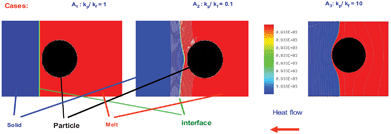 | ||
| Fig. 1 Thermal fields obtained with the numerical model. | ||
In the pushing mechanism there are two main forces which act on the particle; the drag and the pushing force which are in equilibrium, as is shown schematically in Fig. 2. The interaction could be modelled using only one particle, as shown in Fig. 1 where the deformation of the interface is located only near the particle. In the pushing mechanism the drag force pushes the particle onto the solidifying interface and the pushing force is a repulsive force which is necessary to compensate for the drag. In the steady state of pushing both forces are in equilibrium and the particle moves ahead of the interface.
 | ||
| Fig. 2 Schematic representation of a steady state of pushing. R = particle radius; Vint = interface velocity, Fr = repulsive force, Fd = drag force and h(r) = distance between the particle and interface. | ||
Modeling is a useful tool to understand this complex phenomenon and predict the critical velocity.22–31 However, there are many aspects that are not completely addressed, such as the effect of a non-planar interface.
The objective of the present investigation is to include in a model the solidification conditions leading to non-planar interfaces in order to describe and predict the critical velocity of the pushing phenomenon. The model has been built in steps of increasing complexity, which started with more simple conditions producing a planar interface, consisting of a spherical particle and uniform thermal conductivity for the three phases.32–36 The results presented here include the effect of the thermal conductivity on the geometrical configuration of the particle–melt–solid which results in a non-planar solid–liquid interface and consequently modifies the conditions for a steady state of pushing and the value of the critical velocity.
B Methods
Model description
The physical situation consists of a spherical particle of radius R immersed in a melt and a solidifying interface moving towards the particle. There are two fields which are affected by the presence of the particle: the fluid flow and the thermal field in the particle vicinity.The drag force is due to the fluid viscosity and the repulsion force which has different origins depending on the physical properties of the materials.13–28
On the other hand, if the thermal conductivities of the particle, melt and solid are different, the thermal field will affect the shape of the interface behind the particle.
The model will predict the equilibrium separation distance between the particle and interface for the steady state of pushing, and the critical velocity to predict the engulfment.
In order to simplify the calculations in this model the shape of the interface is given only by the thermal field. The drag force depends on the interface shape, the distance between the interface and the particle and the velocity of the fluid. On the other hand, the pushing force is a function of the interface shape and the distance between the interface and the particle.
This configuration of the model provides the possibility to decouple the calculation in three parts as shown in Fig. 3.
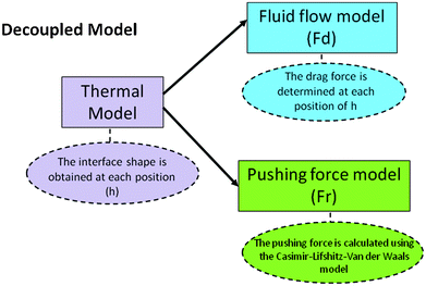 | ||
| Fig. 3 Decoupled model. | ||
First the temperature field is calculated as a function of time and the interface shape is obtained, this process is repeated for at least six different separation distances between the particle and interface and each shape is saved for later use.
Second, the drag force (Fd) on the particle is calculated with the fluid flow model. The range of interface velocities was 1 × 10⁻¹⁰ m s−1 to 10−4 m s−1 which covers the range of velocities normally present in many solidification processes and where there may be a steady state of pushing. Third, the repulsion force (Fr) is calculated using the Casimir–Lifshitz–Van der Waals model at each position.
The equilibrium point occurs when both forces Fd and Fr are equal, the corresponding distance is the separation distance for the steady state of pushing, the coupling is performed as shown in Fig. 9 in the Results section
The thermal model
The thermal model is decoupled from the fluid flow field; this simplification is assumed since the heat flow due to conduction is much higher than both the heat flow due to convection and the latent heat release.9 The interface shape depends on the particle–interface separation h(r) and the thermal conductivities of the particle, melt and solid system. The model includes a solid spherical particle of radius, R, with a thermal conductivity, kp, immersed in a melt with thermal conductivity, km. The mesh employed to discretize the domain is shown in Fig. 4. | ||
| Fig. 4 The axis-symmetrical domain and mesh used for the thermal model. | ||
The solidification process is time dependant and is modelled assuming axial symmetry in an axi-symmetrical domain. A constant heat flow is imposed on the left and the other boundaries are assumed to be isolated. The shape and position of the interface is determined following the isotherm of the solid temperature of the material. The ratio between the thermal conductivities of the particle and melt employed in the calculations is kp/km = 0.1. These values simulate the cases of particles of oxides in a metal melt, where the ratio is in the range between 0.15 and 0.4 (e.g.: kAl2O3/kZn = 0.15 and kTiO2/kAl = 0.40).
The numerical solutions of the heat conduction equation were obtained using a finite element method. The domain was discretized using 50![[thin space (1/6-em)]](https://www.rsc.org/images/entities/char_2009.gif) 000 quadrilateral elements with first order interpolation functions for the temperature field. The resulting mesh is refined around the particle. The numerical solutions were obtained using a Newton–Raphson method with a tolerance of 0.01%. The dynamic time dependant part was solved employing the Crank–Nicholson method with a variable time step adjusted by the Adams–Bashforth method.37
000 quadrilateral elements with first order interpolation functions for the temperature field. The resulting mesh is refined around the particle. The numerical solutions were obtained using a Newton–Raphson method with a tolerance of 0.01%. The dynamic time dependant part was solved employing the Crank–Nicholson method with a variable time step adjusted by the Adams–Bashforth method.37
The fluid flow model
The objective of the fluid flow model is to calculate the drag force on the particle generated by the relative motion between the particle and interface. The drag force tends to push the particle towards the advancing interface. The drag force is calculated numerically from the velocity field which is obtained solving the Navier–Stokes equations by a finite element method.The melt is considered to be a Newtonian fluid in a laminar flow regime associated with a Reynolds number much less than one. The flow is assumed to be in a steady state and have axi-symmetrical symmetry. The boundary conditions imposed are that there is no slip on the spherical particle surface and in one side of the domain there is a constant flow velocity compatible with the interface velocity which simulates the solidification process.
The mesh employed to discretize the domain is shown in Fig. 5 for the axi-symmetric assumption. The domain was discretized using 30000 and 50000 quadrilateral elements, with second order interpolation functions for the velocity and first order for the pressure. The resulting system of equations was solved employing the Picard method.
 | ||
| Fig. 5 The axis-symmetrical domain and mesh used for the fluid flow model, with an enlargement around the particle. | ||
The model was run for at least six different positions of the particle with separation distances from the interface from a maximum value of 2R and a minimum value of hmin = 10−8 m. This minimum value is assumed to be the minimum film thickness which can be considered as fluid.7,38–40 A different mesh was constructed for each separation distance particle–interface (h). The interface shape at each h was obtained from the simulation of the thermal field following the melting temperature isotherm at each time step. At each particle position the model was run for eleven different interface velocities.
The present model for the drag force was validated comparing the results obtained for the case of a planar interface with the values predicted by the modified Stokes equation valid for small separations between the particle and sink, with very good agreement. Details of the calculations and the results for a planar interface are presented elsewhere.30–36
The pushing force model
In the general theory proposed by Chernov et al.,7,9 the pushing force is a denominated disjoining pressure which is composed of three main components; the Van der Waals or dispersion force, the Debye or electrostatic force and the structural component arising from the ordering of the liquid with respect to the solid which contributes to an entropy repulsion. In the present calculations only the first is considered since it is always present in any particle, melt and solid system. Moreover, its influence in the pushing process may be strong enough to determine the pushing and capture process.The Lifsitz–Van der Waals force is responsible for many important processes where small particles interact among themselves, as in the solid–liquid interface, or with other larger particles, as in chemical flocculation, agglomeration of particles and small particles interacting with microscopic particles.41
The Van der Waals forces employed in the present calculations were proposed by Lifshitz and coworkers42–44 which for small separation distances between a spherical particle and a non-planar solid interface can be written as shown in eqn (1). This equation is applied to a system in which the film is not metallic and the sign of the parameter B3 is negative in order to have pushing. The value of B3 of 1 × 10⁻²¹ J is selected since it is in the lower range of values calculated and proposed in the literature.9,11,45,46
 | (1) |
The repulsive, or pushing, force is the Casimir–Lifshitz–Van der Waals force which is calculated for a spherical particle (1) where r is the distance from the particle vertical axis, h(r) is the separation between the interface and the particle; B3 is the Casimir–Lifshitz–Van der Waals constant which is taken as B3 = 1 × 10⁻²¹ J. Both forces; the drag and the Casimir–Lifshitz–Van der Waals forces, are decoupled and therefore calculated separately at each particle position as the solid–liquid interface moves. The equilibrium position for the steady state of pushing is obtained when both forces, Fd and Fr, are equal. This method is suitable since it has been previously shown that the transient state is reached almost instantaneously due to the short range of both forces; the Casimir–Lifshitz–Van der Waals force and the drag force are of the order of 1/h3.2,3,7,35 In view of this, the transient period to the steady state of pushing is neglected. The integration of eqn (1) is performed numerically by the adaptive trapezoid method within a scatter of 5%.
Results and discussion
Results of the temperature fields
The calculations for the thermal field are obtained considering a spherical particle with kp/km = 0.1. The radii used in the calculations were 1 μm, 10 μm and 50 μm. The solid phases were modeled as materials with high viscosity 106 times the viscosity of the melt.The results show that for separation distances between the particle and interface above 2R, the melt temperature isotherm of 933 K is planar and becomes convex as the particle approaches the interface, as shown in Fig. 6.
 | ||
| Fig. 6 Interface shape at equivalent times for different particle interface separations. | ||
Results of the fluid flow fields
The results of the drag force on the particle calculated numerically from the velocity field in the fluid flow model for a convex interface and different separations of the particle–interface were applied assuming a constant viscosity of 1.5 × 10⁻³ Pa s for the melt and the same density for the particle and melt of 2700 kg m−3. The interface is assumed to be a sink with the equivalent flow required for solidification at a given velocity.The drag force was calculated for a range of interface velocities, from 10−10 m s−1 to 1 × 10⁻⁴ m s−1; three particle radii, 50 μm, 10 μm and 1 μm; and six different values of h. The drag force depends on the particle radius and interface velocity.
The results show that the fluid flow is continuous around the particle with no separation lines and very regular with a velocity that increases in the narrow gap between the particle and interface. A typical field is shown in Fig. 7 for kp/km = 0.1 and a particle radius of 50 μm. The drag force obtained for the case of a convex interface is, at least, one order of magnitude smaller than the corresponding drag force obtained for a planar interface at the same interface–particle separation, as shown in Fig. 8(a).
 | ||
| Fig. 7 Fluid flow field around the particle. R = 50 μm; Vint = 2.22 × 10⁻⁶ m s−1 and h = 1 × 10⁻⁶ m. | ||
 | ||
| Fig. 8 (a) Drag force as a function of interface velocity; (b) repulsion force as a function of interface velocity. | ||
Results of the pushing force model
The values of repulsive force calculated using eqn (1) are independent of interface velocity and their magnitude for the case of a convex interface are smaller than the corresponding repulsion force obtained for a planar interface, as shown in Fig. 8(b).The values of Fr and Fd calculated with the models are compared and the intersection between the Fr and the Fd is located, at this point both are equal and correspond to the steady state of pushing for that particle radius, interface–particle distance (h) and interface velocity, as shown in Fig. 9. This procedure is used to determine the equilibrium velocity Veq and the equilibrium distance heq. Repeating this procedure for other solidification conditions makes it possible to obtain a relation between the interface velocity and the separation distance for the steady state of pushing at each particle radius.
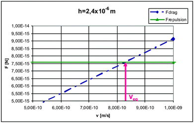 | ||
| Fig. 9 Drag and repulsion force as a function of interface velocity. | ||
The results are shown in Fig. 10 in a log–log graph where it is observed that for a convex interface the equilibrium separation distance is non-linear. On the other hand, for a planar interface the relation is linear. Comparing both lines it is observed that the line corresponding to the convex interface approaches the line for the planar interface at very low interface velocities; on the other hand at larger velocities the equilibrium separation distance for a given velocity is one order of magnitude higher than for a planar interface.
 | ||
| Fig. 10 The equilibrium separation distance between the particle and interface for the steady state of pushing as a function of the interface velocity for the convex and planar interface. R = 50 μm ,10 μm and 1 μm. | ||
In Fig. 10 the critical velocity for pushing (Vc), the highest velocity at which the particle can be pushed, can be obtained considering the minimum thickness (hmin) of the fluid melt which can be considered as such. This minimum thickness is taken as 10−8 m, which is about 10 times the atomic separation distance.1,40–42 Assuming this, the critical velocity for pushing is obtained as the point where each line intercepts the axis in Fig. 10. In such cases the critical velocities for a convex interface and 50 μm particle radius is 2 × 10⁻⁶ m s−1 which when compared with the critical velocity corresponding to a planar interface of 2.22 × 10⁻⁷ m s−1 is 10 times slower. This is due, particularly, to the lower drag force in the case of a convex interface, which is a consequence of the shape of the solidifying interface permitting easier access of the melt to the interface.
Similar relations are obtained for smaller particles of 10 μm and 1 μm, which are shown in Fig. 10, with similar patterns as for the case of the 50 μm particle. The deviation from linearity, however, decreases with the particle radius.
For a given solidification velocity, the equilibrium distance increases as the particle radius decreases indicating that the critical growth velocity increases as the radius decreases, for both planar and convex interfaces. For a convex interface the critical velocities obtained from Fig. 10 are 2 × 10⁻⁶ m s−1, 6 × 10⁻⁶ m s−1 and 1.65 × 10⁻⁵ m s−1 for particle radii of 50, 10 and 1 μm, respectively.
The above critical velocities correspond to an alumina particle in an aluminium melt; however, if the melt is water and the particle melt thermal conduction ratio is 0.1 the critical velocities for particles of radii 50, 10 and 1 μm are 2.8 × 10⁻⁶ m s−1, 6.8 × 10⁻⁶ m s−1 and 2.45 × 10⁻⁵ m s−1, respectively. For a planar interface the corresponding critical velocities are 3.4 × 10⁻⁷ m s−1, 1.645 × 10⁻⁶ m s−1 and 14.7 × 10⁻⁵ m s−1.
In Fig. 11 these values are compared with the experimental results of the measured critical velocities for a wide variety of particle sizes, shapes and materials which were reported in the literature by several authors. It is observed that the planar interface model fits most of the results with a wide scatter and the convex model predicts critical velocities which are normally larger than the experimentally measured ones. On the other hand, the lower limit of the data is predicted by a concave interface.36 It indicates that non-planar interfaces have an important influence in the model that could explain this deviation of the “ideal” planar interface.
 | ||
| Fig. 11 Critical velocities for pushing in water, comparison between experiments and model. | ||
In the present model only the Lifshitz–Van der Waals force is considered and in a melt like water the polar forces could be even stronger than the Lifshitz–Van der Waals force, that is; including them in a model with a convex interface would result in even higher critical velocities for pushing. In addition the particle–interface configuration for an isolated particle such as that shown in Fig. 6 is highly unlikely since it is an unstable configuration and the particle may roll over easily. Moreover, the particles used in the experiments were not spherical in most cases. A particle with an irregular shape will tend to face the largest flat face on the solidifying interface producing much larger drag forces and consequently lower critical velocities. That is, there are effects that somehow compensate each other and modeling including non spherical particles must be performed to analyze the effect of particle shape.
Summary and conclusions
From the model results presented above of the interaction between a particle and a solidifying interface, the following conclusions can be obtained:1 The drag and the Casimir–Lifshitz–Van der Waals pushing forces are significantly weaker for a convex interface than for a flat interface at equilibrium.
2 The equilibrium separation distance between the particle and interface as a function of the interface velocity for convex and planar interfaces are similar at very low interface velocities; on the other hand, at larger velocities the equilibrium separation distance of the convex interface could be one order of magnitude higher.
3 The equilibrium separation distance for pushing is around one order of magnitude higher for a planar interface than for a convex interface.
4 The critical velocity for pushing that may be predicted with the model for a convex interface is one order of magnitude higher than for a planar interface at each particle radius.
5 The comparison of predicted and experimental critical velocities as a function of particle size in water show good agreement for the case of a flat interface.
6 A steady state of pushing with a convex interface is unlikely for spherical particles.
List of symbols
| B3 | Casimir–Lifshitz–Van der Waals constant = 1 × 10⁻²¹ J |
| R | Particle radius |
| Fd | Drag force |
| Fr | Repulsion force |
| h | Particle–interface separation distance |
| r | Generic radius |
| kp | Thermal conductivity of the particle |
| km | Thermal conductivity of the melt and solid |
| hmin | Minimum particle–interface separation distance = 10−8 m |
| Vint | Interface velocity |
| Veq | Equilibrium velocity for pushing |
| heq | Equilibrium separation distance |
| Vc | Critical velocity for pushing |
Acknowledgements
The authors acknowledge the support from CONICET (Consejo Nacional de Investigaciones Científicas y Técnicas) Argentina.References
- M. V. Pikunov, The behavior of suspended impurities during crystallization. Non ferrous metals, their treatment and working, Moscow: Metallurgizdat., 1957, 56–67 Search PubMed.
- E. Dzyaloshinskii, E. M. Lifshitz and L. P. Pitaevskii, General theory of Van der Waals Forces, Sov. Phys. Usp., 1961, 4, 153–176 CrossRef.
- D. R. Uhlmann, B. Chalmers and K. A. Jackson, Interaction between particles and a solid–liquid interface, J. Appl. Phys., 1964, 35, 2986–2993 CrossRef CAS.
- G. F. Bolling and J. Cisse, A theory for the interaction of particles with a solidifying front, J. Cryst. Growth, 1971, 10, 56–66 CrossRef CAS.
- A. W. Neumann, D. J. van Oss and J. Szekely, Kolloid. Z. Z. Polym., 1973, 251, 415–423 CAS.
- S. N. Omenyi, A. W. Neumann and J. of Ap., Phys, 1976, 47, 3956–3962 CAS.
- A. A. Chernov, D. E. Temkin and S. M. Mel'nikova, Sov. Phys. Crystallogr., 1976, 21, 4 Search PubMed.
- J. Cisse and G. F. Bolling, J. Cryst. Growth, 1971, 10, 67–76 CrossRef CAS.
- A. A. Chernov and D. E. Temkin, in Crystal Growth and Materials, ed. E. Kaldis and H. J. Sheel, North Holland, Amsterdam, 1977, pp. 3–77 Search PubMed.
- D. Shangguan, S. Ahuja and D. M. Stefanescu, Metall. Trans. A, 1992, 23, 669–680 CrossRef.
- C. E. Schvezov and F. Weinberg, Interaction of iron particles with a solid–liquid interface in lead and lead-alloys, Metall. Trans. B, 1985, 16, 367–375 CrossRef.
- Y. Fasoyinu, C. E. Schvezov and F. Weinberg, Int. Sol. Proc. Pergamon., 1990, 243 CAS.
- H. Shibata, H. Yin, S. Yoshinaga, T. Emi and M. Sizuki, In situ observation of engulfment and pushing of nonmetallic inclusions in steel melt by advancing melt/solid interface, ISIJ Int., 1998, 38, 149–156 CrossRef CAS.
- Q. Han and J. D. Hunt, Particle pushing: critical flow rate required to put particles into motion, J. Cryst. Growth, 1995, 152, 221–227 CrossRef CAS.
- S. Chang and D. M. Stefanescu, A model for inverse segregation: The case of directionally solidified Al-Cu alloys, Acta Materialia, 1996, 44, 2227–2235 CrossRef CAS.
- S. Sen, B. K. Dhindaw, D. M. Stefanescu, A. Catalina and P. A. Curreri, Melt convection effects on the critical velocity of particle engulfment, J. Cryst. Growth, 1997, 173, 574–584 CrossRef CAS.
- J. K. Kim and P. K. Rohatgi, The effect of the diffusion of solute between the particle and the interface on the particle pushing phenomena, Acta mater., 1998, 46, 1115-l123 Search PubMed.
- S. Sen, F. Juretzko, D. M. Stefanescu, B. K. Dhindaw and P. Curreri, In situ observations of interaction between particulate agglomerates and an advancing planar solid–liquid interface microgravity experiments, J. Cryst. Growth, 1999, 204, 238–242 CrossRef CAS.
- A. V. Catalina, S. Mukherjee and D. Stefanescu, Metall. Mater. Trans. A, 2000, 31, 2559 CrossRef.
- V. Andris V. Bune, S. Sen, S. Mukherjee, A. Catalina and D. M. Stefanescu, Effect of melt convection at various gravity levels and orientations on the forces acting on a large spherical particle in the vicinity of a solidification interface, J. Cryst. Growth, 2000, 211, 446–451 CrossRef.
- A. W. Rempela and M. G. Worster, Particle trapping at an advancing solidification front with interfacial-curvature effects, J. Cryst. Growth, 2001, 223, 420–432 CrossRef.
- H. S. Udaykumar and L. Mao, Sharp-interface simulations of dendritic solidification of solution, Int. J. Heat Mass Transfer, 2002, 45, 4793 CrossRef.
- L. Hadji, Modelling and asymptotic analysis of particle–interface interaction, Mathematical and Computer Modelling, 2002, 36, 147–156 CrossRef.
- J. W. Garvin and H. S. Udaykumar, Particle-solidification front dynamics using a fully coupled approach, part I: methodology, J. Cryst. Growth, 2003, 252, 451–466 CrossRef CAS.
- J. W. Garvin and H. S. Udaykumar, Particle-solidification front dynamics using a fully coupled approach, part II: comparison of drag expressions, J. Cryst. Growth, 2003, 252, 467–479 CrossRef CAS.
- M. Kolbe, X. R. Liu, T. Volkmann, R. Röstel, P. K. Galenko, G. Eggeler, B. Wei and D. M. Herlach, Interaction of solid ceramic particles with a dendritic solidification front, Materials Science and Engineering A, 2004, 375–377, 524–527 CrossRef.
- J. W. Garvin and H. S. Udaykumar, Drag on a particle being pushed by a solidification front and its dependence on thermal conductivities, J. Cryst. Growth, 2004, 267, 724–737 CrossRef CAS.
- A. E. Corte, Vertical migration of particles in front of a moving freezing plane, J. Geophys. Res., 1962, 67(3), 1085–1090 CrossRef.
- J. W. Garvin, Y. Yang and H. S. Udaykumar, Multiscale modeling of particle-solidification front dynamics, part II: pushing-engulfment transition, Int. J. Heat Mass Transfer, 2007, 50, 2969–2980 CrossRef.
- E. M. Agaliotis, M. R. Rosenberger, A. E. Ares and C. E. Schvezov, Numerical calculation of the drag force applied to particle pushing, J. of Cryst. Growth., 2007, 310(7–9), 1366–1370 Search PubMed.
- M. R. Rosenberger, E. M. Agaliotis and C. E. Schvezov, in Modelización numérica de la interacción de partículas con una interfase de solidificación, Análisis de problemas con interfaces móviles, ed. M. Cruchaga and G. Nonato, en MECOM XXIV, 2005, pp. 137–150, (ISSN 1666-6070) Search PubMed.
- M. R. Rosenberger E. M. Agaliotis and C. E. Schvezov, Modelización de la interacción de partículas con interfases de solidificación, Anales AFA 17, La Plata, 2005, pp. 228–233, (ISSN 185-1158) Search PubMed.
- M. R. Rosenberger, E. M. Agaliotis and C. E. Schvezov, Numerical Modeling of Interaction of Particles with Solidifying Interfaces, The Rohatgi Honorary Symp. on Solidif. Process. of Metal Matrix Composite, Nikhil Gupta and Warren Hunt, 2006 TMS Annual Meeting & Exhibition, San Antonio, TX, USA, 2006, pp. 309–320 Search PubMed.
- E. M. Agaliotis, M. R. Rosenberger, C. E. Schvezov and A. E. Ares, Analysis of the interaction of particles with non-planar solidifying interface, ed. David DeYoung, Light Metals 2008 Cast Shop Technology, TMS, 2008, vol. 3, pp. 823–827 Search PubMed.
- C. E. Schvezov, in Dynamic Calculations for Particle Pushing, Solidification, ed. W. H. Hofmeisteret al., TMS, USA, 1999, pp. 251–261 Search PubMed.
- E. M. Agaliotis, M. R. Rosenberger, A. E. Ares and C. E. Schvezov, Modeling the interaction of particles with a concave solidifying interface, Proc. from XII modeling of cast. weld. and advanced solidification process, 2009, pp. 209–217 Search PubMed.
- S. C. Chapra and R. P. Canale, Numerical methods for engineers, McGraw-Hill, 2005 Search PubMed.
- K. V. Sharp and R. J. Adrian, Transition from laminar to turbulent flow in liquid filled microtubes, Exp. Fluids, 2004, 36, 741–747 CrossRef CAS; K. V. Sharp and R. J. Adrian, Exp. Fluids, 2005, 38(1), 132 CrossRef.
- K. Travis, B. Tood and D. Evans, Departure from Navier–Stokes hydrodynamics in confined liquids, Phys. Rev. E, 1997, 55, 4288 CrossRef CAS.
- R. L. Daugherty and A. C. Ingersoll, Mecánica de los fluidos, 1964, p. 348 Search PubMed.
- L. Belloni, Colloidal interactions, J. Phys.: Condens. Matter, 2000, 12, R549 CrossRef CAS.
- . E. M. Lifshitz, Soviet Physics, J. Exptl. Theoret. Phys., 1956, 2, 73–83 Search PubMed.
- I. E. Dzaloshinskii, E. M. Lifshitz and L. P. Pitaevskii, Soviet Physics, J. Exptl. Theoret. Phys., 1960, 37, 161–170 Search PubMed.
- E. Dzyaloshinskii, E. M. Lifshitz and L. P. Pitaevskii, General theory of Van der Waals Forces, Sov. Phys. Usp., 1961, 4, 153–176 CrossRef.
- H. Krupp, Adv. Colloid Interface Sci., 1967, 1, 111–239 CrossRef CAS.
- J. Gregory, Adv. Colloid Interface Sci., 1969, 2, 396–417 CrossRef.
| This journal is © The Royal Society of Chemistry 2012 |