Enhanced hydrogen separation by vertically-aligned carbon nanotube membranes with zeolite imidazolate frameworks as a selective layer†
Lei
Ge
a,
Aijun
Du
b,
Meng
Hou
c,
Victor
Rudolph
a and
Zhonghua
Zhu
*a
aThe University of Queensland, School of Chemical Engineering, Brisbane 4072, Australia. E-mail: z.zhu@uq.edu.au; Fax: 61 7 3365 4199; Tel: 61 7 33653528
bThe University of Queensland, Australian Institute of Biotechnology and Nanotechnology, Brisbane, Australia
cThe University of Queensland, School of Mechanical and Materials Engineering, Brisbane, Australia
First published on 29th October 2012
Abstract
Vertically-aligned carbon nanotube (VACNT) membranes show very high permeation fluxes due to the inherent smooth and frictionless nature of the interior of the nanotubes. However, the hydrogen selectivities are all in the Knudsen range and are quite low. In this study we grew molecular sieve zeolite imidazolate frameworks (ZIFs) via secondary seeded growth on the VACNT membranes as a gas selective layer. The ZIF layer has a thickness of 5–6 μm and shows good contact with the VACNT membrane surface. The VACNT supported ZIF membrane shows much higher H2 selectivity than Ar (7.0); O2 (13.6); N2 (15.1) and CH4 (9.8). We conclude that tailoring metal–organic frameworks on the membrane surface can be an effective route to improve the gas separation performance of the VACNT membrane.
1. Introduction
Membrane science and technology, aimed at decreasing production costs, equipment size, energy utilization and waste generation, have been recognized as important tools to develop new industrial processes for sustainable growth and to solve some global problems.1–3 An important application has been found in gas separation methods. Since polymeric membranes have been commercially produced since the 1980s, membrane separation shows a bright prospect to displace traditional separation processes (such as adsorption and distillation) because membrane separation is more economically competitive. The extended market for membrane gas separation requires further exploration of the membrane materials; novel and high performance membranes with both high selectivity and high permeability, including polymer, carbon, ceramic, metal and mixed matrix membranes, have been studied by many researchers. Among them, vertically-aligned carbon nanotubes (VACNTs), with ordered cylindrical pores and smooth carbon layers, may provide a separation method that requires less energy for applications such as gas separation and the selective separation of nanoparticles, microorganisms, or biomolecules.4–10The inspiration of VACNT membranes was initiated from atomic simulation studies. The transport diffusivities of light gases (H2 and CH4) in carbon nanotubes (CNTs) and in zeolites were evaluated and compared, which showed that the transport rates in CNTs were orders of magnitude faster than that in zeolites. The exceptionally high transport rates result from the inherent smooth and frictionless nature of the interior of the nanotubes.11–13 Carbon nanotubes were therefore predicted to have flux properties far exceeding those of any other known inorganic materials and proposed as one of the most promising membrane materials. Hinds et al.4 and Holt et al.14 confirmed experimentally the high permeability of the CNT membranes by synthesising free-standing and silicon-chip supported VACNT membranes. The gas permeation fluxes were indeed orders of magnitude higher than those predicted by the Knudsen model; the ideal gas selectivities were similar to the Knudsen selectivity for non-hydrocarbon gases, while slightly higher than the Knudsen selectivity for hydrocarbons. Lin et al.15 also fabricated a VACNT membrane on a porous α-alumina support by a multi-step method, and the membrane diffusivity was about four times larger than the values predicted from the Knudsen diffusion model. Later, Falconer et al.16 prepared high-density, vertically aligned carbon nanotube membranes via chemical vapour decomposition (CVD) and solvent evaporation. The gas permeability was much higher than previous VACNT membranes and approximately 450 times higher than the Knudsen predicted diffusion, while the selectivity was within the Knudsen range. The high gas permeation in the above references indicates that the CNTs are vertically aligned to the membrane surface and behave as the fast diffusion channel for the gases. Moreover, the permeability can be further improved by increasing the areal density of CNT forests. Despite its high permeability, the gas selectivity of a VACNT membrane is still in the Knudsen range, which is insufficient for separation applications and requires further improvement.
With the purpose of enhancing the gas selectivity, we grew a thin metal–organic framework (MOF) layer on the surface of the VACNT membrane. Zeolite imidazolate frameworks (ZIFs), a subclass of MOFs consisting of inorganic metal ions or metal clusters coordinated with organic imidazole/imidazolate ligands, were chosen here as the selective layer due to their sodalite cage like structure and pore windows between 0.3–0.36 nm. The unique structure enables suppression by the molecular sieving of larger gas molecules and contributes to the hydrogen selectivity of the composite membrane.17,18 The properties of the ZIF-8 layer and the corresponding ZIF–VACNT membranes were studied, and the permeation behaviours of the membranes were compared. To the best of our knowledge, this is the first reported success in growing MOFs on aligned carbon nanotubes to make such MOF–VACNT membranes for improving gas separation performance.
2. Experimental section
2.1 Vertically-aligned carbon nanotube growth
The aligned carbon nanotube arrays were grown on a quartz substrate by a CVD process of a gas mixture consisting of a catalyst source (ferrocene) and a carbon source (camphor), using the pyrolysis apparatus as outlined in an earlier study.19 A two-stage furnace system fitted with a quartz tube (inner diameter: 47 mm, length: 1.1 m) was used as the reactor. The mixture of the ferrocene (Sigma-Aldrich, 99% pure) and camphor (Sigma-Aldrich, 99.5% pure) with a camphor–ferrocene weight ratio adjusted to 10![[thin space (1/6-em)]](https://www.rsc.org/images/entities/char_2009.gif) :
:![[thin space (1/6-em)]](https://www.rsc.org/images/entities/char_2009.gif) 1 was put into a quartz boat and placed inside the first part of the quartz tube. The commercial quartz substrates, which had been subjected to cleaning with acetone, were located in the second part of the quartz tube at a measured distance from the boat. Before the CVD process, Ar gas (Coregas, 99.999%) initially flowed through the tube reactor to remove the residual air as the second furnace was heated up to the CVD temperature, 900 °C. After the second furnace attained the CVD temperature, the camphor–ferrocene mixture was heated up in the first furnace with a heating rate of 15 °C min−1 until the temperature reached ∼155 °C. Argon gas was then passed through the quartz tube at a flow rate of 1.1 L min−1 to blow the camphor–ferrocene mixture vapour into the second furnace. The concentration of water vapour in the gas flow was controlled by applying an argon stream passing through a water saturator at a flow rate of 5 mL min−1 with a corresponding concentration of water in the gas flow of around 80 ppm. The thermal CVD was conducted at 900 °C for 30 min, and after that, the reactor was cooled to room temperature under pure Ar atmosphere with the moist argon switched off. A deposit of carbon was found on the substrates and the inner surface of the tube reactor.
1 was put into a quartz boat and placed inside the first part of the quartz tube. The commercial quartz substrates, which had been subjected to cleaning with acetone, were located in the second part of the quartz tube at a measured distance from the boat. Before the CVD process, Ar gas (Coregas, 99.999%) initially flowed through the tube reactor to remove the residual air as the second furnace was heated up to the CVD temperature, 900 °C. After the second furnace attained the CVD temperature, the camphor–ferrocene mixture was heated up in the first furnace with a heating rate of 15 °C min−1 until the temperature reached ∼155 °C. Argon gas was then passed through the quartz tube at a flow rate of 1.1 L min−1 to blow the camphor–ferrocene mixture vapour into the second furnace. The concentration of water vapour in the gas flow was controlled by applying an argon stream passing through a water saturator at a flow rate of 5 mL min−1 with a corresponding concentration of water in the gas flow of around 80 ppm. The thermal CVD was conducted at 900 °C for 30 min, and after that, the reactor was cooled to room temperature under pure Ar atmosphere with the moist argon switched off. A deposit of carbon was found on the substrates and the inner surface of the tube reactor.
2.2 Vertically-aligned carbon nanotube membrane fabrication
The inter-tube gaps of the as-synthesized CNT array on the quartz support were filled with epoxy resin (LECO co. epoxy resin: 811-563-103, hardener: 812-519-haz, monomer: hardener = 100![[thin space (1/6-em)]](https://www.rsc.org/images/entities/char_2009.gif) :
:![[thin space (1/6-em)]](https://www.rsc.org/images/entities/char_2009.gif) 14). The solvent-free low viscosity epoxy mixture penetrated into the aligned CNT matrix and filled up the gaps under vacuum. The CNT–epoxy composite was degassed at room temperature for 1–2 days to remove air bubbles and allow curing. The surface of the coated CNT appeared transparent, indicating that the black CNT was completely covered by the epoxy overlayer. The membranes were removed from the quartz substrate by hydrofluoric acid and washed with deionised water followed by drying. A simple mechanical polishing method was employed to remove the epoxy overlayer and to open the closed tips of the CNTs. Specifically, a polishing machine (Buehler Vector Head/Beta Polishing Machine) and 2500-mesh sand paper were used to carefully sand off the surface of the CNT membrane disk. The sanding process continued until black CNTs appeared on the surface, and then further polishing was conducted to adjust the membrane thickness and open the CNT caps. The sanded composite membrane was immersed in 15% hydrochloric acid solution for about 1 day to remove most of the catalyst residues. After that, the membranes were washed with deionized water, followed by drying under vacuum. The derived epoxy–VACNT membranes are flat and crack free.
14). The solvent-free low viscosity epoxy mixture penetrated into the aligned CNT matrix and filled up the gaps under vacuum. The CNT–epoxy composite was degassed at room temperature for 1–2 days to remove air bubbles and allow curing. The surface of the coated CNT appeared transparent, indicating that the black CNT was completely covered by the epoxy overlayer. The membranes were removed from the quartz substrate by hydrofluoric acid and washed with deionised water followed by drying. A simple mechanical polishing method was employed to remove the epoxy overlayer and to open the closed tips of the CNTs. Specifically, a polishing machine (Buehler Vector Head/Beta Polishing Machine) and 2500-mesh sand paper were used to carefully sand off the surface of the CNT membrane disk. The sanding process continued until black CNTs appeared on the surface, and then further polishing was conducted to adjust the membrane thickness and open the CNT caps. The sanded composite membrane was immersed in 15% hydrochloric acid solution for about 1 day to remove most of the catalyst residues. After that, the membranes were washed with deionized water, followed by drying under vacuum. The derived epoxy–VACNT membranes are flat and crack free.
2.3 Synthesis of ZIF-8 nanocrystals
The ZIF-8 nanocrystals were prepared by a procedure reported previously.20 A solution of Zn(NO3)2·6H2O (0.2933 g) in 20 mL methanol was rapidly added to a solution of 2-methylimidazole (Hmim) (0.649 g) in 20 mL methanol under stirring. The mixture turned to a milky colour gradually and was stirred continually for 1 h. The nanocrystals were then separated by centrifugation and washed with methanol. The products were dried at 40 °C in air.2.4 Growth of the ZIF-8 thin film on VACNT membranes
The ZIF-8 thin layer was prepared on the VACNT membrane by secondary seeded growth.21 Before synthesis, one side of the VACNT membrane was carefully rubbed with dry ZIF-8 seeds. After seeding, the VACNT membrane was placed in a beaker, which was filled with the synthesis solution as described above. The hydrothermal reaction was conducted at room temperature for 3 h or 6 h and the derived ZIF–VACNT membranes were denoted as ZVM-3 and ZVM-6, respectively. After hydrothermal synthesis, the membranes were washed with fresh methanol and degassed at 150 °C for 2 h.2.5 Characterization
The X-ray diffraction spectra (XRD) of ZIF-8 and the VACNT supported membranes were obtained with a Bruker Advanced X-Ray Diffractometer (40 kV, 30 mA) with Cu-Kα (λ = 0.15406 nm) radiation at a scanning rate of 1° min−1 from 5° to 90°. Attenuated total reflection Fourier transform infrared spectroscopy (ATR FT-IR) spectra were obtained using a Nicolet 5700 ART spectrometer with an average of 64 scans in the range 400–3800 cm−1. A JEOL JSM 6300 operated at 5 kV was used for scanning electron microscopy (SEM), and a JEOL 6610 coupling with an Oxford SDD energy dispersive X-ray spectrometer (EDS) was used for elemental analysis. Transmission electron microscopy (TEM) and high resolution transmission electron microscopy (HRTEM) were performed on a JEOL JEM-2100 microscope, with accelerating voltages of 200 kV. The samples were dispersed by sonication in a mixture of ethanol and isopropanol, then deposited on a holey carbon TEM grid and dried. Raman spectra were obtained with an ALMEGA Dispersive Raman instrument (Thermo Nicolet) using the 514 nm wavelength of a 10 mW Ar laser. A 100× objective lens was employed to focus an illuminated spot of ∼2 μm diameter on the sample. N2 physisorption isotherms of the samples were obtained using a Micromeritics TriStar 3020 at −196 °C, after degassing samples for 24 h at 150 °C. The corresponding specific surface areas (Sg) were calculated by the Langmuir equation at a relative pressure (P/Pθ) between 0.005 and 0.05. Total pore volumes (Vp) were evaluated at relative pressures (P/Pθ) close to unity, while the micropore volume was gained from the Dubinin–Radushkevich (DR) method by taking data points in the P/Pθ range 0.01–0.3.Gas permeation experiments were carried out using a variable feed pressure and constant volume permeation system, described elsewhere.22 Before testing, the gas line and the cell were purged with target gas from the cylinder and evacuated several times. The membrane was glued on a porous stainless steel support (porosity > 30%, pore size: ∼30 μm, Metallic Membrane Co. of Nanjing University of Technology) and sealed with a high vacuum sealant (Torr seal, Varian). The membrane thickness is 130 to 150 μm in this study. Then the membranes were held under vacuum for approximately 5 min before exposing to the selected gas at a specific pressure. Pure hydrogen, nitrogen, oxygen, argon, carbon dioxide or methane (99.99–99.999%, Coregas, Australia) was introduced to the upstream side of the membrane, and the pressure of both sides was measured by a pressure transducer (MKS, Baratron 722A). Both pressure transducers were connected to a computer for data logging. Tests were carried out at 25 °C by controlling the pressure of the feed stream to a desired value, and evacuating the permeate side to a vacuum. The pressure gradient was kept constant before measuring. The permeate stream valve was then closed, allowing the pressure to increase in the permeate reservoir due to gas permeation through the membrane. The collected data were used to calculate the permeance according to eqn (1),23
 | (1) |
3. Results and discussion
3.1 Characterization of vertically-aligned CNT membranes
Fig. 1 shows some information about the as-synthesized carbon nanotubes from the gas phase catalytic CVD. As can be seen in Fig. 1a, the CNT arrays show a high degree of vertical alignment and are packed well, forming a uniform carpet-style forest with a thickness of ∼215 μm. The high magnification SEM image in Fig. 1b shows that most of the carbon nanotubes are quite straight and parallel to each other. Near-unity tortuosities were estimated to be around 1.3, while the density of the VACNT arrays is ∼1010 nanotubes cm−2. The typical TEM image of the CNTs derived from CVD growth is shown in Fig. 1c. The CNTs have an average inner-diameter around 5 nm and each CNT consists of ∼15 layers of concentric graphene sheets with a layer distance of ∼0.34 nm. Most of the tubes possess a hollow inner cavity and well-crystallized graphitic sheets. The graphitic structure of the as-synthesized VACNT arrays is also proven by the Raman spectra (Fig. 1d).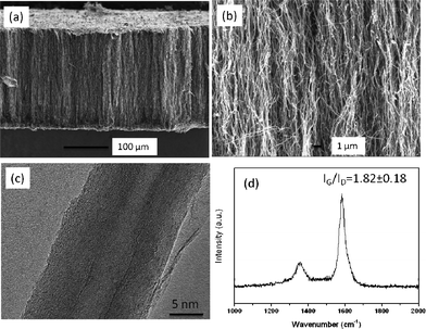 | ||
| Fig. 1 Cross-section SEM images of aligned carbon nanotube arrays (a, b), HRTEM image of the derived carbon nanotube (c) and Raman spectrum of aligned carbon nanotubes (d). | ||
As reported in the references, VACNT membranes (<10 μm thickness) have previously been fabricated by filling the carbon nanotube interspace with a polymer or ceramic matrix, such as polystyrene and silicon nitride.4,14,15 In this study, however, the as-synthesized thick (>200 μm) aligned carbon nanotube arrays generate a larger diffusion resistance for the polymer filling. Therefore, smaller monomer molecules are preferred rather than larger molecules to reduce the diffusion resistance in the CNT interspaces and achieve complete filling of the CNT gaps. Herein, the dense membranes were fabricated by filling the VACNT arrays with epoxy, similar to the reported route to fill the super long VACNT arrays.19,22 The typical cross-section and surface morphologies of the VACNT membrane are shown in Fig. 2. As can be seen in Fig. 2a, a dense structure is formed by the polymer filling into the CNT spacing; the polymer and carbon nanotubes are connected closely. Some highly-curved CNTs shown in Fig. 2b are caused by sample cutting. The gas permeance of the epoxy filled VACNT membranes were measured to examine the successful polymer filling. The hydrogen permeance of these membranes with close ended CNTs are around 10−10 mol m−2 s Pa, which is much smaller than the VACNT membrane with open tubes (∼10−6 mol m−2 s Pa). This indicates that the CNT gaps are fully filled by the epoxy resin and the gas mainly transports through the channels of the CNTs. The tiny permeance of the close ended VACNT membrane reflects gas diffusion in the epoxy polymer or perhaps leakage from the membrane module. Fig. 2c shows the polished surface of the aligned carbon nanotube membranes for the evaluation of areal density. Some broken carbon nanotubes can be observed on the polymer surface, together with some pin holes in the polymer (arrows shown in Fig. 2c). The tips of the CNTs have been removed by the polishing, leaving most of the carbon nanotube channels open for gas transportation.
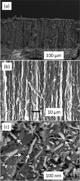 | ||
| Fig. 2 SEM images of the VACNT membrane with the tube gap filled by epoxy (a, b: cross-section; c: surface after polishing). | ||
3.2 Characterization of ZIF-8 nanocrystals
Fig. 3 shows the X-ray diffraction pattern of the synthesized ZIF-8 crystals. A high degree of crystallinity can be observed and all the peaks can be indexed to the cubic I-43m space group, in precise consistency with those ZIF-8 XRD patterns reported previously.20,21,24 Based on the Rietveld refinement, the observed pattern and the simulated pattern show high similarity, which further confirms the formation of pure crystalline ZIF-8. Detailed results of the Rietveld refinement of ZIF-8 can be found in the supplementary information as Table S1.† The morphological features of ZIF-8 crystals are examined under HRTEM (Fig. 4), showing sharp hexagonal crystals with uniform sizes between 50 and 100 nm. As can be seen in Fig. 5, the nitrogen isotherm of ZIF-8 nanocrystals belongs to a type I isotherm, indicating the microporous nature of ZIF-8. The Langmuir surface area of the ZIF-8 crystals (2380 m2 g−1) was calculated by using the data points with P/Pθ ranging from 0.01 to 0.10 along the curve of the isotherm plot, which corresponds to the formation of a monolayer of adsorbate molecules.25 The BET surface area of derived ZIF-8 crystals is 1782 m2 g−1, which is higher than previously reported ZIF-8 crystals by the same room temperature synthesis.20 The micropore volume is 0.97 cm3 g−1 calculated by the Dubinin–Radushkevich method in the P/P0 range 0.01–0.3.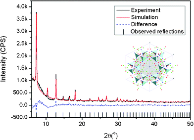 | ||
| Fig. 3 Rietveld refinement of the X-ray diffractogram of ZIF-8 crystals and the structure diagram of ZIF-8 - insert (light blue: ZnN4 tetrahedra, blue: N, red: C, green: H). | ||
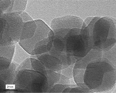 | ||
| Fig. 4 TEM image of as-synthesized ZIF-8 crystals. | ||
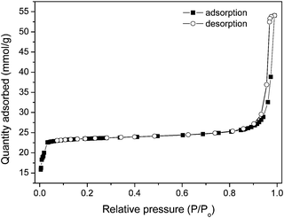 | ||
| Fig. 5 N2 sorption isotherms of the ZIF-8 crystals. | ||
3.3 Characterization of VACNT supported ZIF-8 membranes
The FTIR spectra of ZIF-8 crystals, VACNT membrane and VACNT supported ZIF-8 membrane (ZVM-6) are shown in Fig. 6. The ZIF-8 crystal (Fig. 6a) shows characteristic infrared bands at around 1585 cm−1 (C![[double bond, length as m-dash]](https://www.rsc.org/images/entities/char_e001.gif) N stretch), 1145 and 995 cm−1 (C–N stretch), in good agreement with previous reports.20 The peaks in the FTIR spectrum of the VACNT membrane (Fig. 6b) are all assigned to the epoxy resin, the polymer filler in the VACNT membrane. The FTIR spectrum shows characteristic infrared bands at around 826 cm−1 (stretching C–O–C of the oxirane group), 1035 cm−1 (stretching C–O–C of ether), 1507 cm−1 (stretching C–C of aromatic) and 1605 cm−1 (stretching C
N stretch), 1145 and 995 cm−1 (C–N stretch), in good agreement with previous reports.20 The peaks in the FTIR spectrum of the VACNT membrane (Fig. 6b) are all assigned to the epoxy resin, the polymer filler in the VACNT membrane. The FTIR spectrum shows characteristic infrared bands at around 826 cm−1 (stretching C–O–C of the oxirane group), 1035 cm−1 (stretching C–O–C of ether), 1507 cm−1 (stretching C–C of aromatic) and 1605 cm−1 (stretching C![[double bond, length as m-dash]](https://www.rsc.org/images/entities/char_e001.gif) C of aromatic rings). For the VACNT supported ZIF-8 membrane, the FTIR spectrum (Fig. 6c) shows features for both ZIF-8 and VACNT, this confirms the growth of ZIF-8 on the VACNT membrane. Slight shifts in the band positions were observed for the VACNT supported ZIF-8 membrane compared with the ZIF-8 crystal, suggesting that chemical interactions have occurred between the ZIF-8 and VACNT membrane.
C of aromatic rings). For the VACNT supported ZIF-8 membrane, the FTIR spectrum (Fig. 6c) shows features for both ZIF-8 and VACNT, this confirms the growth of ZIF-8 on the VACNT membrane. Slight shifts in the band positions were observed for the VACNT supported ZIF-8 membrane compared with the ZIF-8 crystal, suggesting that chemical interactions have occurred between the ZIF-8 and VACNT membrane.
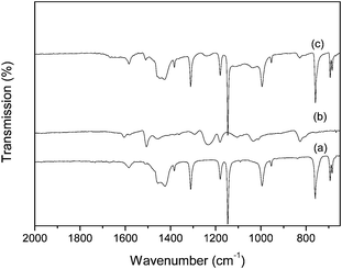 | ||
| Fig. 6 FTIR spectra of synthesized (a) ZIF-8 crystals, (b) VACNT membrane and (c) ZVM-6 membrane. | ||
To avoid unselective gas leakage in membrane applications, the ZIF-8 selective layer should be continuous and dense, and the selective layer and the support preferably integrate with each other. The morphology and composition information of the VACNT supported ZIF-8 membrane (ZVM-6) are shown in Fig. 7. The typical flat, dense and continuous ZIF-8 layer can be observed with a thickness of 5–6 μm (Fig. 7a). And as can be seen in Fig. 7b, the alignment of carbon nanotubes from the VACNT layer is not affected by secondary seeded growth. Some highly curved CNTs apparent are caused by sample cutting. In Fig. 7c, the ZIF-8 crystals link together without a visible grain-boundary. No through pinholes are observed on this well intergrown layer. The disordered structure of the top VACNT layer is attributed to the ZIF-8 seeding process and mechanical polishing of the VACNT layer. The layer compositions are revealed by EDS, as shown in Fig. 7d. The upper ZIF-8 layer shows an obvious zinc signal while the lower VACNT layer presents no zinc signal. The iron signal from the VACNT layer is attributed to the catalyst residue left over from the CNT synthesis process. The iron signal from the VACNT layer is attributed to the catalyst residue left over from the CNT synthesis process. The evidence of catalyst residue can be seen in Fig. S1.† On one hand, some of the catalyst particles are covered with a carbon shell during the CVD synthesis and are inaccessible by the acid. On the other hand, the catalyst residues (Fe particles) on the external surface of the carbon nanotubes were also covered by epoxy resin and therefore cannot be eliminated by a HCl acid wash. As to the Fe particles encapsulated inside the CNTs, they could be removed by acid. Once the mechanical polishing was conducted to open the CNTs caps, however, some residual catalysts may still remain due to the diffusion resistance to the acid inside the nano-channels. They will block the gas transport path and limit the molecular transport to some extent. Moreover, it is worthwhile to note that there is no clear interface between the ZIF-8 layer and the VACNT membrane layer from the SEM images, indicating tight adhesion between the ZIF-8 layer and the VACNT membrane. The process of rubbing the seed material into the surface appears to facilitate a strong attachment of the ZIF-8 crystals on the surface of the VACNT membrane due to the favourable interactions between the polymer and organic ligands of MOFs.26–28 These seeds provide nucleation sites for crystal growth into the dense ZIF layer during the secondary growth process, and this layer adheres tightly to the VACNT membranes.
 | ||
| Fig. 7 Cross-section SEM images of (a) ZVM-6 membrane, (b) magnified VACNT layer, (c) magnified ZIF-8 layer and (d) EDS spectrum of ZIF-8 layer and VACNT layer of ZVM-6 membrane | ||
3.4 Gas permeation performance of VACNT membranes and VACNT supported ZIF-8 membranes
Fig. 8 shows the gas permeances and the hydrogen selectivities versus other gases for the VACNT membrane, measured by the permeation method described earlier. Since the mean free path of gases at room temperature (∼67 nm) is more than one order of magnitude larger than the pore diameter of the given VACNT membranes (∼5 nm), the gas transportation through the VACNT membranes is expected to be in the Knudsen range. Based on the Knudsen diffusion, the gas permeability is proportional to the square root of the inverse ratio of the molecular weights. The measured hydrogen permeance is the highest (2.37 × 10⁻⁶ mol m−2 s−1 Pa−1), while carbon dioxide shows the lowest permeance (4.85 × 10⁻⁷ mol m−2 s−1 Pa−1). As shown in this figure, the predicated Knudsen permeance is also calculated as in our previous study,19 the Knudsen permeance of hydrogen is 8.63 × 10⁻⁸ mol m−2 s−1 Pa−1. The measured gas permeances are about two orders of magnitude higher than the Knudsen predicted permeance, consistent with the permeation enhancement phenomenon of aligned carbon nanotube membranes reported previously.4,5,14–16,19,29 Such high gas diffusivity can be attributed to the smooth interior CNT surface of the VACNT membranes in which molecular collisions do not have any backscattering, but keep all forward momentum upon reflections down the CNT channels.5 Unlike the randomly-scattered Knudsen diffusion, the specular momentum transfer along the tube channel significantly increases the diffusivities, to an extent much higher than kinetic theory.11,12 Despite the high diffusivities, the pore sizes of the VACNT membranes are much larger than the kinetic diameter of gas molecules, the CNT channels cannot provide effective selectivity to various gases, therefore the gas separation factor is still governed by the Knudsen mechanism. The measured relative selectivities of hydrogen are quite low, scattered around the theoretical Knudsen selectivity range. The ideal H2 selectivity to CH4, N2, O2, Ar and CO2 are 2.58, 3.48, 3.82, 4.14 and 4.89, respectively.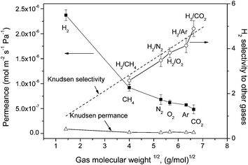 | ||
| Fig. 8 Single-gas permeances of different gases and the separation factor for H2 over other gases on the VACNT membrane as a function of molecular weight. | ||
After growing the ZIF-8 layer on the VACNT membrane, the gas permeances and hydrogen selectivities are shown in Fig. 9. As the kinetic diameter of large gases (such as N2 and CH4) is larger than pore window of ZIF-8, the transportation of larger gases through the membrane can be inhibited. Clearly, the permeance of hydrogen is much higher than those of other gases, in accordance with the previous reports on ZIF thin membranes (ZIF-8, ZIF-22, ZIF-90).30–32 The gas permeance, instead of being dependent on the gas molecular weight as in the VACNT membrane, shows a correlation with the kinetic diameter of the gases in the VACNT supported ZIF membranes. Specifically, the gas permeance goes down when the kinetic diameter of the gases increases. It is interesting to note that methane, with the largest kinetic diameter (3.8 Å) among these test gases, does not exhibit the lowest permeance. Similar results can also be observed in thin ZIF membranes, such as alumina supported ZIF-7 membranes33,34 and titania supported ZIF-22 membranes.31 Due to the existence of grain boundaries in the polycrystalline ZIF layer, the gas diffusion in the ZIF layer follows not only the molecular sieving diffusion, but also the Knudsen diffusion. Knudsen-like mass transport could contribute to the slightly higher permeance of CH4 than that of N2 because CH4 has a smaller molecular weight than N2.33 In this case, relative selectivity of hydrogen to CH4 will be lower than that of N2. In addition, a previous study shows that methane can slowly pass through the 3.4 Å pore aperture of ZIF-8, suggesting that the framework structure may be somewhat flexible.35
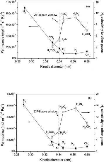 | ||
| Fig. 9 Single-gas permeances of different gases and the separation factor for H2 over other gases on the (a) ZVM-3 and (b) ZVM-6 as a function of kinetic diameter. | ||
Based on different growth durations, ZVM-6 shows a higher separation performance than ZVM-3. The ideal separation factors of H2 to CO2, Ar, O2, N2 and CH4 in the ZVM-6 membrane can reach 4.9, 7.0, 13.6, 15.1 and 9.8, respectively. Molecular sieve separation is then deduced since all the gas selectivities except for H2/CO2 in both membranes are higher than those in the VACNT membrane. For H2/CO2 gas selectivity, only a slight improvement can be observed, which is probably because the kinetic diameter of CO2 is smaller than the ZIF-8 pore window. As a whole, the combined gas diffusion mechanisms are proposed for the VACNT supported ZIF-8 membrane. In the VACNT-epoxy layer, the gas diffusion and transports are the same as the VACNT membrane, while the gas transportation through the ZIF-8 layer can be governed by both molecular sieving (gas pass through the pore window of ZIF-8) and the Knudsen diffusion (gas pass through the grain boundaries of the polycrystalline ZIF-8). The molecular sieving by the ZIF-8 micropore window generates high hydrogen selectivity to larger gases, however the non-selective Knudsen diffusion through the grain boundaries of the polycrystalline ZIF-8 deteriorates the entire gas selectivity. As to the gas permeance drop in VACNT supported ZIF-8 membranes, it can be attributed to the higher diffusion barrier in the ZIF-8 layer compared to the smooth and ordered channel of CNTs. The interface between the ZIF-8 layer and the VACNT layer may also contribute to the increased gas diffusion resistance.
The gas permeances drop off with increasing ZIF-8 growth time from 3 to 6 h. Higher growth times result in thicker MOF layers and this leads to higher hydrogen selectivity but at the cost of slightly lower permeance. Since the aligned CNT membranes were fabricated and measured, the membranes show very high permeances which are orders of magnitude higher than the Knudsen prediction. In this study, with the growth of a selective MOF layer, the selectivity dramatically increases while the permeance is partly compromised. This trade-off may still be very worthwhile because the permeance can still be higher than the Knudsen predicated value. In addition, synthesizing a more compact thin molecular sieving layer or fabricating carbon nanotubes with tip-gated MOFs via contra-diffusion synthesis could be promising routes to achieve high gas selectivity while also maintaining a high permeance of the VACNT membrane. On the other hand, as to ZIF thin membranes and ZIF mixed matrix membranes in previous references, membranes with a high gas separation performance can be achieved by incorporating ZIF into the polymer matrix, such as ZIF-8–Matrimid36,37 and ZIF-8–polysulfone.38 With increasing ZIF loading amount, the relative selectivity of hydrogen to methane/carbon dioxide can exceed 100. In addition, compared to the VACNT supported thin ZIF-8 membrane in this study, thin ZIF membranes show a higher gas permeance with similar or higher hydrogen selectivity, such as alumina supported ZIF-90, ZIF-7 and ZIF-8 membranes,32,33,39 and polymer supported ZIF-8 membranes.28 Hydrogen permeance of those membranes is higher than 10−7 mol m−2 s−1 Pa−1, with the hydrogen relative selectivity larger than 10. Among these membranes, fabricating a mixed matrix membrane can be one of the most effective, cost-saving and controllable methods to achieve high permeability and selectivity of various gases.
4. Conclusions
Aligned carbon nanotube forests fabricated by CVD growth have been made into membranes by epoxy filling the interstices followed by mechanical polishing to open the CNTs. These membranes show characteristically high permeation fluxes (1–2 orders more than the Knudsen flow) and low hydrogen selectivities (H2/Ar = 4.14, H2/O2 = 3.82, H2/N2 = 3.48, H2/CH4 = 2.58 and H2/CO2 = 4.89).To improve the gas separation performance, molecular sieved zeolite imidazolate frameworks, with a pore window of 0.34 nm, were synthesized onto the surfaces of the aligned carbon nanotube membranes. A ZIF-8 layer of about 5–6 μm thickness was deposited on the top of the open-ended VACNT membrane via secondary seeded growth for 6 h at 90 °C. With the aid of the ZIF-8 selective layer, the ideal separation factors of H2 to CO2, Ar, O2, N2 and CH4 of the ZVM-6 membrane are significantly improved, reaching up to 4.9, 7.0, 13.6, 15.1 and 9.8, respectively.
The selectivity can be further improved by making the ZIF-8 layer thicker but this is at the expense of permeance. However, balancing the permeance and selectivity should be considered to improve both requirements of the aligned carbon nanotube membrane simultaneously. At the current stage, compared to other ZIF thin membranes and ZIF mixed matrix membranes, the VACNT supported thin ZIF-8 membranes do not prevail in terms of cost effectiveness. However, the growth of the MOF selective layer opens up an alternative way to improve the gas selectivity of the VACNT membrane, which could contribute to our existing knowledge on the VACNTs membrane system and achieve a membrane system that could make full use of the superflux of CNTs and the molecular sieving of MOFs. Future work can be focused on fabricating a more effective thinner molecular sieving layer or tip-gating carbon nanotubes in order to further increase its hydrogen selectivity while still maintaining the high permeance of VACNT membranes.
Acknowledgements
Financial support by the Australian Research Council (ARC) discovery project is greatly appreciated. The first author also likes to acknowledge the support from IPRS (Endeavour International Postgraduate Research Scholarship, Australia) and UQRS (University of Queensland Research Scholarship).References
- R. W. Baker, Membrane technology and applications, Wiley, 2004 Search PubMed.
- B. Koros, J. Membr. Sci., 2007, 300, 1 CrossRef CAS.
- F. M. Dautzenberg and M. Mukherjee, Chem. Eng. Sci., 2001, 56, 251 CrossRef CAS.
- B. J. Hinds, N. Chopra, T. Rantell, R. Andrews, V. Gavalas and L. G. Bachas, Science, 2004, 303, 62 CrossRef CAS.
- M. Majumder, N. Chopra and B. J. Hinds, ACS Nano, 2011, 5, 3867 CrossRef CAS.
- S. A. Miller and C. R. Martin, J. Am. Chem. Soc., 2004, 126, 6226 CrossRef CAS.
- S. A. Miller, V. Y. Young and C. R. Martin, J. Am. Chem. Soc., 2001, 123, 12335 CrossRef CAS.
- A. I. Lopez-Lorente, B. M. Simonet and M. Valcarcel, Anal. Chem., 2010, 82, 5399 CrossRef CAS.
- B. Suarez, Y. Moliner-Martinez, S. Cardenas, B. M. Simonet and M. Valcarcel, Environ. Sci. Technol., 2008, 42, 6100 CrossRef CAS.
- A. S. Brady-Estévez, S. Kang and M. Elimelech, Small, 2008, 4, 481 CrossRef.
- D. M. Ackerman, A. I. Skoulidas, D. S. Sholl and J. K. Johnson, Mol. Simul., 2003, 29, 677 CrossRef CAS.
- A. I. Skoulidas, D. M. Ackerman, J. K. Johnson and D. S. Sholl, Phys. Rev. Lett., 2002, 89, 185901 CrossRef.
- A. I. Skoulidas, D. S. Sholl and J. K. Johnson, J. Chem. Phys., 2006, 124, 054708 CrossRef.
- J. K. Holt, H. G. Park, Y. Wang, M. Stadermann, A. B. Artyukhin, C. P. Grigoropoulos, A. Noy and O. Bakajin, Science, 2006, 312, 1034 CrossRef CAS.
- W. Mi, Y. S. Lin and Y. Li, J. Membr. Sci., 2007, 304, 1 CrossRef CAS.
- M. Yu, H. H. Funke, J. L. Falconer and R. D. Noble, Nano Lett., 2009, 9, 225 CrossRef CAS.
- O. M. Yaghi, M. O'Keeffe, N. W. Ockwig, H. K. Chae, M. Eddaoudi and J. Kim, Nature, 2003, 423, 705 CrossRef CAS.
- X.-C. Huang, Y.-Y. Lin, J.-P. Zhang and X.-M. Chen, Angew. Chem., Int. Ed., 2006, 45, 1557 CrossRef CAS.
- L. Ge, L. Wang, A. Du, M. Hou, V. Rudolph and Z. Zhu, RSC Adv., 2012, 2, 5329 RSC.
- J. Cravillon, S. Munzer, S.-J. Lohmeier, A. Feldhoff, K. Huber and M. Wiebcke, Chem. Mater., 2009, 21, 1410 CrossRef CAS.
- S. R. Venna and M. A. Carreon, J. Am. Chem. Soc., 2010, 132, 76 CrossRef CAS.
- F. Du, L. Qu, Z. Xia, L. Feng and L. Dai, Langmuir, 2011, 27, 8437 CrossRef CAS.
- C. Yacou, S. Smart and J. C. Diniz da Costa, Energy Environ. Sci., 2012, 5, 5820 CAS.
- Y. C. Pan, Y. Y. Liu, G. F. Zeng, L. Zhao and Z. P. Lai, Chem. Commun., 2011, 47, 2071 RSC.
- S. Brunauer, P. H. Emmett and E. Teller, J. Am. Chem. Soc., 1938, 60, 309 CrossRef CAS.
- M. A. Snyder and M. Tsapatsis, Angew. Chem., Int. Ed., 2007, 46, 7560 CrossRef CAS.
- A. Centrone, Y. Yang, S. Speakman, L. Bromberg, G. C. Rutledge and T. A. Hatton, J. Am. Chem. Soc., 2010, 132, 15687 CrossRef CAS.
- L. Ge, W. Zhou, A. Du and Z. Zhu, J. Phys. Chem. C, 2012, 116, 13264 CAS.
- M. Majumder, N. Chopra, R. Andrews and B. J. Hinds, Nature, 2005, 438, 44 CrossRef CAS.
- H. Bux, A. Feldhoff, J. Cravillon, M. Wiebcke, Y.-S. Li and J. Caro, Chem. Mater., 2011, 23, 2262 CrossRef CAS.
- A. Huang, H. Bux, F. Steinbach and J. Caro, Angew. Chem., Int. Ed., 2010, 49, 4958 CrossRef CAS.
- A. Huang and J. Caro, Angew. Chem., Int. Ed., 2011, 50, 4979 CrossRef CAS.
- Y. Li, F. Liang, H. Bux, W. Yang and J. Caro, J. Membr. Sci., 2010, 354, 48 CrossRef CAS.
- Y. S. Li, F. Y. Liang, H. Bux, A. Feldhoff, W. S. Yang and J. Caro, Angew. Chem., Int. Ed., 2010, 49, 548 CrossRef CAS.
- W. Zhou, H. Wu, T. J. Udovic, J. J. Rush and T. Yildirim, J. Phys. Chem. A, 2008, 112, 12602 CrossRef CAS.
- Q. L. Song, S. K. Nataraj, M. V. Roussenova, J. C. Tan, D. J. Hughes, W. Li, P. Bourgoin, M. A. Alam, A. K. Cheetham, S. A. Al-Muhtaseb and E. Sivaniah, Energy Environ. Sci., 2012, 5, 8359 CAS.
- M. J. C. Ordonez, K. J. Balkus Jr, J. P. Ferraris and I. H. Musselman, J. Membr. Sci., 2010, 361, 28 CrossRef CAS.
- B. Zornoza, B. Seoane, J. M. Zamaro, C. Téllez and J. Coronas, ChemPhysChem, 2011, 12, 2781 CrossRef CAS.
- Z. Xie, J. Yang, J. Wang, J. Bai, H. Yin, B. Yuan, J. Lu, Y. Zhang, L. Zhou and C. Duan, Chem. Commun., 2012, 48, 5977 RSC.
Footnote |
| † Electronic Supplementary Information (ESI) available. See DOI: 10.1039/c2ra21460a |
| This journal is © The Royal Society of Chemistry 2012 |
