Tailored graphene materials by chemical reduction of graphene oxides of different atomic structure
Cristina
Botas
a,
Patricia
Álvarez
a,
Clara
Blanco
a,
M. Dolores
Gutiérrez
b,
Pablo
Ares
c,
Reza
Zamani
d,
Jordi
Arbiol
e,
Joan R.
Morante
d and
Rosa
Menéndez
*a
aInstituto Nacional del Carbón, INCAR-CSIC, Apdo, 73, 33080, Oviedo, Spain. E-mail: rosmenen@incar.csic.es
bUniversidad de Oviedo, Julian Clavería 8, 33006, Oviedo, Spain
cNanotec Electrónica S.L. Ronda de Poniente, 12, 28760, Tres Cantos, Madrid, Spain
dCatalonia Institute for Energy Research, IREC, 08930, Barcelona, Spain
eInstitució Catalana de Recerca i Estudis Avançats, ICREA, 08010, Barcelona, Spain
First published on 13th August 2012
Abstract
Graphene materials with different characteristics in terms of sheet size and defects (structural and/or functional groups) were obtained by the reduction with hydrazine of two graphene oxides with similar oxygen content, but with functional groups of different type and location. The oxides were prepared from two synthetic graphites with distinct crystalline structure. Our research has obtained experimental evidence of a greater reactivity of the oxygen functional groups located in the interior of the aromatic domains on the basal planes (mainly epoxy) and a lower reactivity of oxygen functional groups located at the edges (mainly carboxyl and OH). Furthermore, these edge-located groups were found to be responsible for hydrogen bonding lateral interactions between sheets (these occur through the residual OH groups), which cause a substantial increase in the size of the reduced graphene oxide with respect to that of the parent graphene oxide. These results offer a way to tailor the characteristics of graphene materials for diverse applications.
1. Introduction
A great deal of effort has been devoted in recent years to the synthesis of graphene by various methods1,2 and especially to the study of its electronic behavior3 with the aim of tuning it to specific potential applications.4 The preparation of graphene by chemical methods, such as the graphene oxide route, offers the possibility of producing it on a large scale and, at the same time, of controlling its quality, depending on: i) the properties of the parent graphite,5,6 ii) the oxidation method used7 and iii) the final reduction of the graphene oxide (GO).8 GOs and reduced graphene oxides (rGOs) are graphene derivatives that exhibit a structure decorated with defects resulting from the oxidation and/or reduction processes.9 These materials are of great interest for applications that involve catalytic processes, among others.10 However, the complexity of the reactions involved in the overall process (oxidation, exfoliation, reduction), in addition to the numerous variables that may affect the bonding of the carbon atoms of the parent graphite, make it very difficult to achieve strict control of the yield and quality of the products.Oxygen functionalities of four kinds are known to be present in GO: epoxy, hydroxyl, carbonyl and carboxyl.11 Generally speaking, epoxy and hydroxyl, located on the basal plane of GO, are considered to be the main functionalities, whereas carbonyl and carboxyl, distributed at the edges, are regarded as minor, although this largely depends on the initial parent graphite crystalline structure. The chemical structure of GO has been the subject of considerable debate for a number of years, and even now no definitive model exists.8,9 After reduction with hydrazine, the oxygen atoms in GO are removed to a large extent12 and the resultant rGO differs markedly from a defect-free graphene.13 Besides, the structural disorder and defects inherited from the GO, the rGO still includes residual oxygen functional groups and N-containing species. The mechanisms involved in the reduction of GO with hydrazine have been proposed in the case of the epoxy groups by Stankovich14 and further investigated by Gao et al.,12 who employed the density functional theory method for this purpose. However, the processes involved in the case of the hydroxyl and carboxyl groups are still unclear. Further experimental evidences are necessary to support these theoretical studies. It is thought that the position of the oxygen functional groups in the interior of the aromatic domains or at the edges conditions the reactivity of GO during reduction.12 This would also have a strong influence on the final chemical/catalytic properties of the graphene materials and would determine their applications.
The aim of this paper is to obtain graphenes of different characteristics by chemical reduction with hydrazine of two GOs of similar oxygen content, but with rather different types and different distributions of the oxygen functional groups. The GOs were characterized in detail at the atomic level by aberration-corrected low energy high resolution transmission electron microscopy (HRTEM), and both GOs and the corresponding chemically reduced ones (rGOs) by AFM, SEM, TEM, Raman spectroscopy and XPS. Data related to the GOs preparation and characterization have been previously reported and will be used to assist the present discussion.6
2. Experimental
2.1. Preparation of GOs
The GOs were prepared from two synthetic graphites6 by the modified Hummers method.15 This method makes use of the Hummers reagents with additional amounts of NaNO3 and KMnO4. Concentrated H2SO4 (360 mL) was added to a mixture of graphite (7.5 g) and NaNO3 (7.5 g), and the mixture was cooled down to 0 °C using an ice bath. KMnO4 (45 g) was added slowly in small doses to keep the reaction temperature below 20 °C. The solution was heated to 35 °C and stirred for 3 h, at which point 3% of H2O2 (1.5 L) was added slowly, giving rise to a pronounced exothermal effect up to 98 °C. The reaction mixture was stirred for 30 min and then centrifuged. The remaining solid material was then washed with 600 mL of water and centrifuged again, this process being repeated until the pH was neutral. A colloidal suspension of GO sheets in purified water (1 mg mL−1) was prepared in 1-L batches, and kept under ultrasound for 10 h. Then the suspension was centrifuged, the supernatant was filtered over cellulose and the solid was discarded.2.2. Characterization of GOs
The structure of the GOs was studied by HRTEM. Aberration-corrected images with sub-angstrom resolution were obtained in a Titan Cube (80–300 keV) TEM fitted with a Field Emission Gun (FEG) and a CEOS aberration corrector at the objective lens. The microscope was operated at 80 keV to avoid sample damage. A drop of the solution was placed on a lacey carbon grid.Further experimental details on the characterization of the GOs by microscopy and spectroscopy techniques are published elsewhere.6
2.3. Preparation of rGOs
GOs were reduced with hydrazine monohydrate in an aqueous solution14 in the presence of a base.16 500 mL of an aqueous solution of GO (1 mg mL−1) was loaded into a 2-L round-bottom flask and hydrazine hydrate (5 mL, ratio 100![[thin space (1/6-em)]](https://www.rsc.org/images/entities/char_2009.gif) :1), ammonia (200 μL) and toluene (10 mL) were then added. Finally, the solution was heated in an oil bath at 100 °C under a water-cooled condenser for 24 h. The base was added to the reaction solution to increase the pH to around 10; at this pH the electrostatic repulsions of GO sheets are maximised. Toluene was added to the reaction mixture to avoid the agglomeration of graphene sheets upon water evaporation.16 As the rGOs are difficult to clean, dialysis membranes were used. The samples were introduced into the membranes, which were in turn inserted into containers with Milli-Q water. The water was replaced until the conductivity of water was the same as that of Milli-Q water.
:1), ammonia (200 μL) and toluene (10 mL) were then added. Finally, the solution was heated in an oil bath at 100 °C under a water-cooled condenser for 24 h. The base was added to the reaction solution to increase the pH to around 10; at this pH the electrostatic repulsions of GO sheets are maximised. Toluene was added to the reaction mixture to avoid the agglomeration of graphene sheets upon water evaporation.16 As the rGOs are difficult to clean, dialysis membranes were used. The samples were introduced into the membranes, which were in turn inserted into containers with Milli-Q water. The water was replaced until the conductivity of water was the same as that of Milli-Q water.
2.4. Characterization of rGOs
The rGOs were characterized by means of elemental analysis, X-ray photoelectron spectroscopy (XPS), Raman spectroscopy, scanning electron (SEM), transmission electron (TEM) and atomic force microscopy (AFM).![[double bond, length as m-dash]](https://www.rsc.org/images/entities/char_e001.gif) C (sp2) at 284.5 eV. The chemical shifts of +1.0, +2.0, +3.0 and +5.0 eV were assigned to the C (sp3) hybridisation, C–OH, C–O–C and C(O)OH functional groups, respectively.18 In a similar way, the O1s and N1s were deconvoluted in the following ranges. In the O1s spectra, the peak at 533 eV was assigned to C–OH groups and the peak at 531 eV was assigned to C–O–C and C(O)OH groups.19,20 In the N1s spectra, the peak at 400.3 eV was assigned to pyrrolic nitrogen, the peak at 398.7 eV corresponds to pyridinic nitrogen and the peak at 401 eV was assigned to graphitic nitrogen.18
C (sp2) at 284.5 eV. The chemical shifts of +1.0, +2.0, +3.0 and +5.0 eV were assigned to the C (sp3) hybridisation, C–OH, C–O–C and C(O)OH functional groups, respectively.18 In a similar way, the O1s and N1s were deconvoluted in the following ranges. In the O1s spectra, the peak at 533 eV was assigned to C–OH groups and the peak at 531 eV was assigned to C–O–C and C(O)OH groups.19,20 In the N1s spectra, the peak at 400.3 eV was assigned to pyrrolic nitrogen, the peak at 398.7 eV corresponds to pyridinic nitrogen and the peak at 401 eV was assigned to graphitic nitrogen.18
3. Results and discussion
3.1. Characterization of GOs
The two GOs used in this study (GO-1 and GO-2) were prepared from two graphites of very homogeneous but different crystalline structure. GO-1 was obtained from a graphite dominantly made of very well oriented structures (10–20 μm width, 50–100 μm length, at the optical microscope) while GO-2 was obtained from a graphite made of small size crystals (1.5–5 μm, at the optical microscope). Details of the basic characterization of the two GOs and parent graphites are provided elsewhere.6 Briefly, GO-1 and GO-2 exhibited a very similar C/O ratio of about 2, as determined by XPS. However, a close analysis of the structure of both GOs revealed fundamental differences between them. GO-1 exhibited an increased amount of sp2 CC bonds (45.1% for GO-1 and 36.2 for GO-2), as well as a considerably larger amount of C–O–C bonds probably located on the basal planes of the layer (39.4 for GO-1 and 13.8 for GO-2). In contrast, GO-2 showed an increased amount of C sp3 atoms (the sp3 C–C bonds representing 4.9% in GO-1 and 11.3% in GO-2), as well as hydroxyl (1.9% for GO-1 and 20.3% for GO-2) and carboxyl groups at the edges of the sheets (10.7% for GO-1 and 19.5% for GO-2). The XPS results were corroborated by Raman spectroscopy and FTIR.6
High resolution imaging of single layers revealed the atomic structure of the GOs, which is presented in Fig. 1 (Fig. 1a and c are original HRTEM images and Fig. 1b and d are Fast Fourier Transformed (FFT) filtered with colors to show the structure more clearly). Four different regions were identified: holes (groups of missing C atoms, indicated in red), disordered or amorphous carbon (indicated in yellow), well ordered graphene areas (indicated in blue) and ordered graphene but with some O/OH or some structural defects (indicated in green). The main differences are to be found in the presence of a greater number of holes resulting from the aggressive oxidation and exfoliation23 (red color, Fig. 1d) and disordered or amorphous carbon mainly at the edges of the holes (yellow color, Fig. 1d) in GO-2. This may be the result of the greater presence of carboxylic groups (10.7% for GO-1 and 19.5% for GO-2) and possibly of edge-located OH groups. In both cases, the pristine graphite structure is only observed in small domains, which means that both graphites have undergone strong oxidation, but the basic structural units are essentially different in the two GOs. It seems clear, therefore, that the less crystalline structure of the parent graphite of GO-26 generated more disordered structures and holes in some regions.
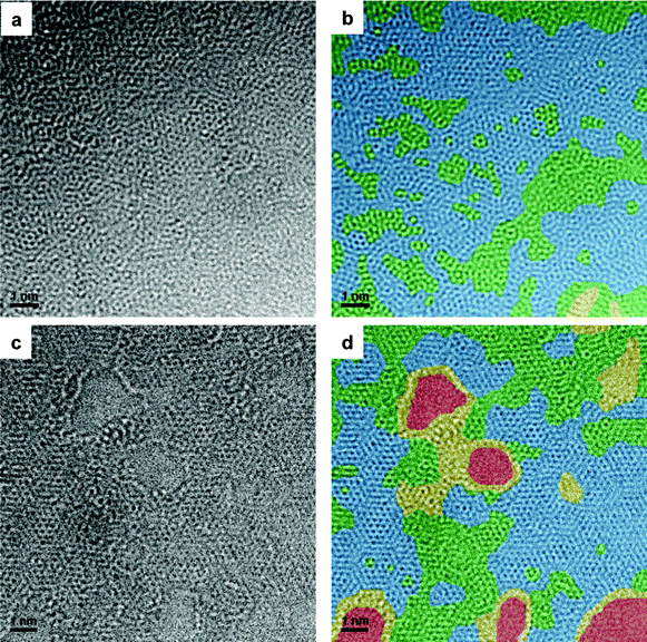 | ||
| Fig. 1 Aberration-corrected low energy (80 keV) HRTEM images of (a, b) GO-1 and (c, d) GO-2. The following colors are used to represent the main structural features: blue, ordered graphene structure; green, ordered graphene structure with some O/OH or some structural defects; yellow, disordered or amorphous graphene and red the holes. The colored images (b) and (d) have been filtered. | ||
In Fig. 2 and 3, the structures observed have been magnified and are shown next to possible atomic simulations. The most abundant structure in GO-2 (red squares in Fig. 3a, FFT filtered in Fig. 3b and inverse FFT image in Fig. 3c with an atomic model in Fig. 3d, which corresponds to the green areas in Fig. 1d) is composed of two hexagons of carbon atoms and a pentagon. In the case of GO-1 (Fig. 2a) the dominant features (yellow, green and blue squares, corresponding to green parts in Fig. 1b) are domains with a graphene structure, which appear to have some O/OH atoms on top of the carbon (epoxy groups) in some positions. Moreover, very few areas with topological defects, such as pentagons, can be seen (red square in Fig. 2a–c). Regions with some atomic defects can be observed in Fig. 2d–l. Possible atomic models are included beside the corresponding figures, in which the O/OH defects are shown by means of red spheres and green bonds. In GO-2, Fig. 3g and 3m show atomic models with no structural defects and Fig. 3j shows O/OH bonded to the carbon atoms of a graphene sheet. Fig. 3n shows the overlapping of two graphene layers, which gives rise to a new pattern consisting of larger and brighter hexagons that have a bright point in the center. These bright points, indicated in the model by white spheres, are the result of the overlapping of two carbon atoms. Around each of these points there are six C–C bonds, each set of three forming one layer. According to the results shown in Fig. 2 and 3, GO-2 has more structural and atomic (O/OH) defects.
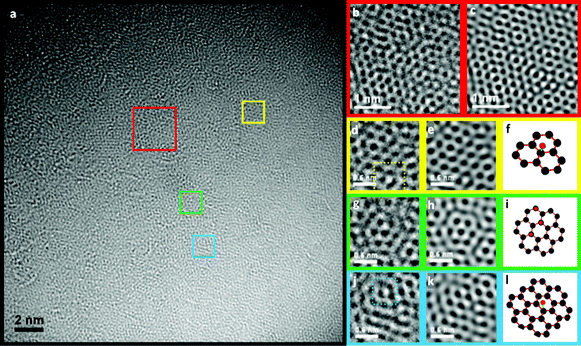 | ||
| Fig. 2 Aberration-corrected low energy (80 keV) HRTEM analysis of GO-1, (a) HRTEM image and FFT filtered (b), (d), (g), (i). The images next to the filtered ones are the corresponding inverse FFT images (c), (e), (h), (k) to make the structure clearer, and (f), (i), (l) are the atomic models of the possible structures with O/OH defects. | ||
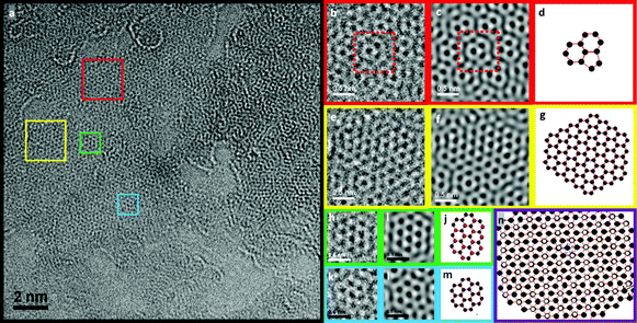 | ||
| Fig. 3 Aberration-corrected low energy (80 keV) HRTEM analysis of GO-2, (a) HRTEM image and FFT filtered (b), (e), (h), (k); the images beside the filtered ones are the corresponding Inverse FFT images (c), (f), (i), (l), and (d), (g), (j), (m) are the atomic models of the possible structures. Image (n) shows an atomic model of a double layer graphene structure, which creates a pattern with larger hexagonal structures. The white atoms represent the overlapping of two carbon atoms that in the HRTEM images stand out by their brightness. | ||
Gómez-Navarro et al.24 observed in the GO they studied only isolated highly oxidized areas, while at least 60% of the surface remained undisturbed. In our case the oxygen significantly altered the initial structure of the basal planes of the parent graphite and only a small number of regions were unaffected, as was also reported by Erickson et al.25 This, together with the different atomic structure and defects exhibited by GO-1 and GO-2 evidences the important role of the type of graphite used as starting material. This also opens up the possibility of obtaining GOs with a different atomic structure in terms of the type and distribution of the oxygen functional groups and the size of the structural domains, which is of great interest for improving the selectivity of the reactions in the preparation of chemically modified graphenes.
3.2. Reduction of GOs
The products obtained by the reduction of the GOs with hydrazine differ substantially from their precursors and from each other. When hydrazine is added to the GO and heated at 100 °C, a black solid is precipitated from the water suspension while rGO-2 remains in suspension (Fig. 4). This different behavior is reflected in the diverse shapes of the aggregated platelets of the rGOs after the removal of the solvent observed by SEM (Fig. 5a and b). Moreover, TEM analysis of both samples confirms a greater degree of sheet folding and stacking in rGO-1 (Fig. 5c) than in rGO-2 (Fig. 5d). It is also worth mentioning that the rGO-2 solid was totally re-dispersed in dimethyl formamide–water, while in the case of rGO-1 dispersal was only partial.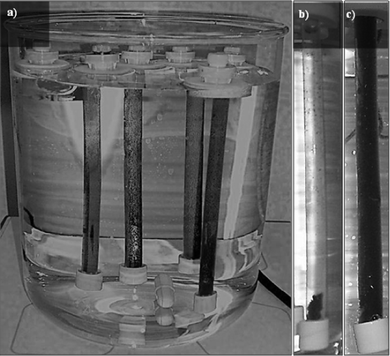 | ||
| Fig. 4 Images of the dialysis system (a) and rGOs (b, c) in dialysis membranes. The suspension of rGO-2 (c) remained stable, while rGO-1 (b) precipitated inside the membrane. | ||
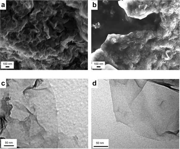 | ||
| Fig. 5 SEM Images of partially reduced graphene oxide sheets (a) rGO-1 and (b) rGO-2 after solvent removal and TEM images of partially reduced graphene oxide sheets (c) rGO-1 and (d) rGO-2. | ||
These diverse behaviors are the result of the increased hydrophobic nature of rGO-1 resulting from the greater decrease in the number of polar functional groups in this sample during hydrazine reduction. Thus, the C/O ratio as determined by elemental analysis of rGO-1 was twice that of rGO-2, (8.6 for rGO-1 and 3.1 for rGO-2). These results were corroborated by XPS, even though there are some differences due to the fact that elemental analysis analyzes the bulk sample, whereas XPS only analyzes the surface (4.0 for rGO-1 and 2.8 for rGO-2).26 The expected incorporation of nitrogen into the carbon matrix as the result of hydrazine exposure is also more evident in the case of rGO-2 (8.6% N vs. 3.5% in rGO-1, as determined by elemental analysis).
3.3. Characterization of rGOs
The reduction process led to a larger amount of Csp2 in rGO-1, as quantified by the C1s XPS analysis (54.9% for rGO-1 and 45.6% for rGO-2, Table 1), which is indicative of a better ordered structure compared to that of rGO-2. The increase in Csp2 in both rGOs with respect to the parent GOs (45.1% for GO-1 and 36.2% for GO-2) is confirmation of the restoration of the graphitic structure upon reduction. This is in agreement with the studies reported by Pulido et al.27 regarding the restoration of the sp2 network in GOs by low temperature reaction with CO. The higher content of active sites (non-sp2 hybridized atoms) in GO led to a higher adsorption of CO than in rGO.| Sample | C1s (%) | O1s (%) | N1s (%) | |||||||
|---|---|---|---|---|---|---|---|---|---|---|
| CC |
C–H C–N | C–OH C–N | CO |
C(O)OH | CO C(O)OH |
C–OH | pyridinic N | pyrrolic N | graphitic N | |
| rGO-1 | 54.7 | 15.6 | 17.4 | 8.9 | 3.2 | 32.3 | 68.4 | 6.0 | 53.4 | 39.4 |
| rGO-2 | 46.2 | 32.1 | 15.3 | 3.7 | 4.1 | 9.9 | 92.4 | 3.0 | 51.8 | 45.2 |
The Raman spectra of the samples (Fig. 6) exhibit a typical graphene-like pattern with a characteristic strong band attributed to the vibration of sp2-bonded carbon atoms in a two-dimensional hexagonal lattice, as well as a D band caused by edges of imperfections. The ID/IG ratio showed an increase for the rGOs in comparison to that of the parent GOs (from 0.89 in GO-1 to 1.05 in rGO-1, and from 0.92 in GO-2 to 1.16 in rGO-2). The G bands also shifted to higher wavelengths in both cases. It has been suggested28 that this could be the result of a decrease in the size of the sp2 domains upon reduction, independent of the increase in their overall presence in the material.
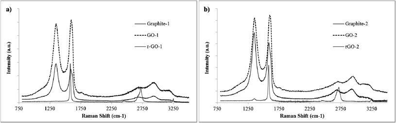 | ||
| Fig. 6 Raman spectra of parent graphites, GOs and rGOs. | ||
Quantification of C sp3 is complicated in these samples, due to overlapping with the C–N bonds. The greater intensity of this peak in rGO-2 may be due to the larger amount of nitrogen incorporated into the graphene sheets (Table 1). Also worth mentioning is the greater number of C(O)OH groups remaining in rGO2 (3.2 for rGO-1 and 4.1 for rGO-2, Table 1).
Analysis of the O1s spectra reveals a much narrower shape in rGO-2 than in rGO-1 (Fig. 7b and e). Although the assignments of these functional groups in the literature are sometimes conflicting,29 the narrower shape indicates that in rGO-2 the oxygen functional groups are all of a similar type. Also of interest is the higher intensity of the peak at 533.0 eV (assigned to C–OH groups)20 in rGO-2, and the wider shape of the rGO-1 curve at higher and lower frequencies.
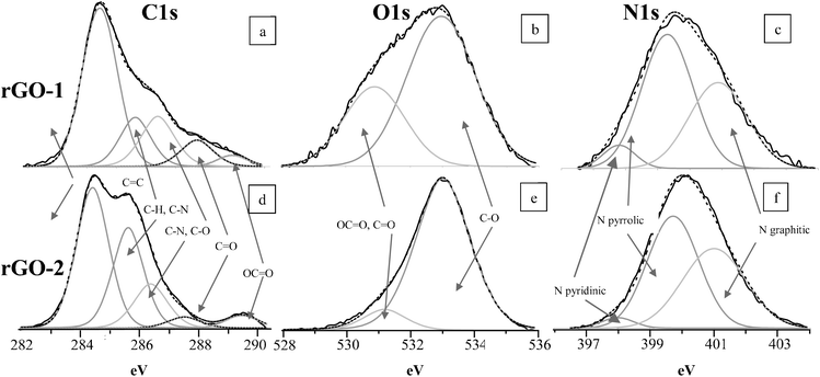 | ||
| Fig. 7 Core level high resolution spectra: C1s (a, d), O1s (b, e) and N1s (c, f) of rGO-1 (a, b, c) and r-GO-2 (d, e, f). | ||
The N1s curves evidence the similar nature of the remaining N-bonds in the platelets from the two samples (Fig. 7 c and f, Table 1) and shows the presence of three types of species, pyridinic N (398.7 eV), pyrrolic N (400.1 eV) and graphitic N (401.8 eV), consistent with other previous results.18 In both cases the most abundant species is pyrrolic N, bonded to two C atoms with two p-electrons localized in the π-conjugated system. In a lower proportion are the graphitic N in which N substitutes a C atom in the hexagonal ring (more abundant in rGO-2, Table 1) and pyridinic N, bonded to two C atoms with one p-electron localized in the π-conjugated system (the latter is more abundant in rGO-1, Table 1). No nitrogen oxide (N–O, at 402.8 eV) is observed in any of the cases.
In order to explain our findings, we considered the characteristics of the parent GOs. Although they have a similar C/O ratio (about 2), their oxygen functional groups are located in different positions. GO-1 exhibits mainly epoxy and OH groups located in the aromatic domains,8 which according to Gao et al.12 are more easily removed, both kinetically and thermodynamically, facilitating the restoration of the graphene structure. This explains the better restoration of the C sp2 network in GO-1. In contrast, GO-2, which has more OH and carboxyl groups, located at the edges of aromatic domains (hole borders) and at the edges of the sheets, experiences more difficulty in restoring the C sp2 network. The presence of holes (as observed by HRTEM), together with the larger contribution of carboxyl groups and edge located OH, support this lower reactivity of GO-2 to hydrazine. Moreover, the greater retention of N by rGO-2 may be the result of the presence of some epoxy groups located at the edges of the aromatic domains. In the presence of hydrazine these will form hydrazino alcohols that are thermodynamically more stable than the corresponding de-epoxidation products at room temperature.12
In addition to the results reported above, AFM studies revealed interesting information about the role played by the functional groups in defining the physical and chemical characteristics of the graphene materials. The size of the sheets of the GO monolayers was 57 × 10−3 μm2 (in the case of GO-1) and 3 × 10⁻³ μm2 (in the case of GO-2), and the average height were 0.9 nm for both, as determined by AFM.6 Surprisingly, rGO-2 showed sheets with an average size as large as 70 × 10−3μm2, and heights of 0.40–2.04 nm, which corresponds to those from monolayers to a few layers sheets (Fig. 8). As the oxygen in the parent GO-2 mainly formed part of the C(O)OH and OH groups, and the C(O)OH are located at the edges of the sheets, as was some of the OH, a possible explanation may be the chemical lateral hydrogen bonds interaction among the sheets of rGO-2 through the residual OH groups located at the edges, resulting in spontaneous self-assemblage.30,31Fig. 8c shows a high resolution image of a rGO-2 sheet, where an internal structure inside the sheet can be observed, reinforcing the idea of the self-assembly of different smaller sheets.
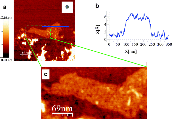 | ||
| Fig. 8 AFM images of reduced graphene oxide sheets (a) rGO-2 monolayer sheet. The grey hexagon in the inset of the image shows the average size of the graphene oxide sheets before the reduction process. (b) Section corresponding to the continuous (blue) horizontal line shown in (a). (c) High resolution image corresponding to the area inside the dashed (green) rectangle in (a). An internal structure can be seen. | ||
4. Conclusions
Reduced graphene oxides with fewer structural defects and less residual oxygen are produced from graphene oxides with oxygen functional groups preferentially located at the interior of the aromatic domains on the basal planes. Moreover, graphene oxides with oxygen functional groups preferentially located at the edges of the sheets yield reduced graphene oxides with an increased sheet size due to inter-sheet hydrogen bonding among the remaining hydroxyls. We have demonstrated experimentally that the efficiency of the reduction does not necessarily depend on the oxygen content of the parent graphene oxide. There is a more active role of the oxygen functional groups in the graphene oxide upon chemical reduction with hydrazine when these groups are located in the interior of the aromatic domains on the basal planes rather than at the edges. These results offer a way to obtain graphene materials with a very different structure (in terms of sheet size and defects) suitable for diverse applications.Acknowledgements
The authors thank MICINN (CONSOLIDER CSD2009-00050; CSD2009 00013 IMAGINE; MAT2010-15138) and Generalitat de Catalunya (2009 SGR 770, NanoAraCat and XaRMAE) for financial support. Dr P. A. thanks MICINN for her Ramon y Cajal contract. C. B. acknowledges a fellowship from FICYT. The authors also thank Dr Pacheco for his assistance in the HRTEM.References
- C. N. R. Rao, A. K. Sood, K. S. Subrahmanyam and A. Govindaraj, Angew. Chem., Int. Ed., 2009, 48, 7752–7777 CrossRef CAS.
- S. Park and R. S. Ruoff, Nat. Nanotechnol., 2009, 4, 217–224 CrossRef CAS.
- P. Avouris, Nano Lett., 2010, 10, 4285–4294 CrossRef CAS.
- C. Flox, J. Rubio-Garcia, R. Nafria, R. Zamani, M. Skoumal, T. Andreu, J. Arbiol, A. Cabot and J. R. Morante, Carbon, 2012, 50, 2372–2374 CrossRef CAS.
- Z. S. Wu, W. Ren, L. Gao, B. Liu, C. Jiang and H.-M. Cheng, Carbon, 2009, 47, 493–499 CrossRef CAS.
- C. Botas, P. Álvarez, C. Blanco, R. Santamaría, M. Granda, P. Ares, F. Rodríguez-Reinoso and R. Menéndez, Carbon, 2012, 50, 275–282 CrossRef CAS.
- D. C. Marcano, D. V. Kosynkin, J. M. Berlin, A. Sinitskii, Z. Sun, A. Slesarev, L. B. Alemany, W. Lu and J. M. Tour, ACS Nano, 2010, 4, 4806–4814 CrossRef CAS.
- D. R. Dreyer, S. Park, C. W. Bielawski and R. S. Ruoff, Chem. Soc. Rev., 2010, 39, 228–240 RSC.
- A. Bagri, C. Mattevi, M. Acik, Y. Chabal, M. Chhowalla and V. Shenoy, Nat. Chem., 2010, 2, 581–587 CrossRef CAS.
- S. Chandra, S. Bag, P. Das, D. Bhattacharya and P. Pramanik, Chem. Phys. Lett., 2012, 519–520, 59–63 CrossRef CAS.
- T. Szabó, O. Berkesi, P. Forgó, K. Josepovits, Y. Sanakis, D. Petridis and I. Dékány, Chem. Mater., 2006, 18, 2740–2749 CrossRef.
- X. Gao, J. Jang and S. Nagase, J. Phys. Chem. C, 2010, 114, 832–842 CAS.
- A. K. Geim and K. S. Novoselov, Nat. Mater., 2007, 6, 183–191 CrossRef CAS.
- S. Stankovich, D. A. Dikin, R. D. Piner, K. A. Kohlhaas, A. Kleinhammes, Y. Jia, Y. Wu, S. T. Nguyen and R. S. Ruoff, Carbon, 2007, 45, 1558–1565 CrossRef CAS.
- W. S. Hummers and R. E. Offeman, J. Am. Chem. Soc., 1958, 80, 1339–1340 CrossRef CAS.
- D. Li, M. B. Muller, S. Gilje, R. B. Kaner and G. G. Wallace, Nat. Nanotechnol., 2008, 3, 101–105 CrossRef CAS.
- P. M. A. Sherwood, in Practical Surface Analysis, vol. 1, Auger and X-ray Photoelectron Spectroscopy, ed. D. Briggs and M. P. Seah, Wiley, New York. 1990, p. 574 Search PubMed.
- D. Deng, X. Pan, L. Yu, Y. Cui, Y. Jiang, J. Qi, W.-X. Li, Q. Fu, X. Ma, Q. Xue, G. Sun and X. Bao, Chem. Mater., 2011, 23, 1188–1193 CrossRef CAS.
- C. Kozlowski and P. M. A. Sherwood, J. Chem. Soc., Faraday Trans. 1, 1984, 80, 2099 RSC.
- D. Yang, A. Velamakanni, G. Bozoklu, S. Park, M. Stoller, R. D. Piner, S. Stankovich, I. Jung, D. A. Field, C. A. Ventrice and R. S. Ruoff, Carbon, 2009, 47, 145–152 CrossRef CAS.
- I. Horcas, R. Fernández, J. M. Gómez-Rodríguez, J. Colchero, J. Gómez-Herrero and A. M. Baro, Rev. Sci. Instrum., 2007, 78, 013705 CrossRef CAS.
- R. García and A. San Paulo, Phys. Rev. B: Condens. Matter, 1999, 60, 4961–4967 CrossRef.
- J. T. Paci, T. Belytschko and G. C. Schatz, J. Phys. Chem. C, 2007, 111, 18099–18111 CAS.
- C. Gómez-Navarro, J. C. Meyer, R. S. Sundaram, A. Chuvilin, S. Kurasch, M. Burghard, K. Kern and U. Kaiser, Nano Lett., 2010, 10, 1144–1148 CrossRef.
- K. Erickson, R. Erni, Z. Lee, N. Alem, W. Gannett and A. Zettl, Adv. Mater., 2010, 22, 4467–4472 CrossRef CAS.
- M Seredych, J. A Rossin and T. Bandosz, Carbon, 2011, 49, 4392–4402 CrossRef CAS.
- A. Pulido, P. Concepción, M. Boronat, C. Botas, P. Alvarez, R. Menéndez and A. Corma, J. Mater. Chem., 2012, 22, 51–56 RSC.
- L. M. Malard, M. A. Pimenta, G. Dresselhaus and M. S. Dresselhaus, Phys. Rep., 2009, 473, 51–87 CrossRef CAS.
- G. Zhang, S. Sun, D. Yang, J. P. Dodelet and E. Sacher, Carbon, 2008, 46, 196–205 CrossRef CAS.
- L. J. Cote, F. Kim and J. Huang, J. Am. Chem. Soc., 2009, 131, 1043–1049 CrossRef CAS.
- L. J. Cote, F. Kim and J. Huang, Adv. Mater., 2010, 22, 1954–1958 CrossRef.
| This journal is © The Royal Society of Chemistry 2012 |