Methanol electrocatalytic oxidation on highly dispersed platinum–ruthenium/graphene catalysts prepared in supercritical carbon dioxide–methanol solution†
Jian
Zhao
*abc,
Lin
Zhang
abc,
Hao
Xue
abc,
Zhaobo
Wang
abc and
Haiqing
Hu
*abc
aKey Laboratory of Rubber-PlasticsMinistry of Education/Shandong Provincial Key Laboratory of Rubber-Plastics, Qingdao University of Science & Technology, China 266042
bKey Laboratory of Organosilicon Chemistry and Material Technology of Ministry of Education, Hangzhou Normal University, Hangzhou, China 31001
cChongqing Key Laboratory of Micro/Nano Materials Engineering and Technology, Chongqing, China 402168. E-mail: zhaojian@gmail.com; Fax: +86 0532 84022725
First published on 26th July 2012
Abstract
An effective, simple, low temperature and environmentally benign supercritical fluid (SCF) route is presented for preparing graphene-supported metal nanoparticles. With the assistance of supercritical carbon dioxide (SC CO2), ultrafine PtRu nanoparticles with an average size of 2.87 nm were very uniformly distributed on the surfaces of functionalized graphene sheets (FGSs) by the reduction of a mixture of H2PtCl6 and RuCl3 precursors. The catalytic property of the as-prepared composites for methanol oxidation was investigated by cyclic voltammetry and chronoamperometry. In comparison with their carbon black (Vulcan XC-72) counterparts, the PtRu/FGSs composites showed considerably improved catalytic activity and stability for methanol oxidation. The high surface area of graphene and even distribution of ultrafine bimetallic particles are vital for the superior electrocatalytic performance of the PtRu/FGSs composites. The findings suggest that highly efficient graphene-supported metallic electrocatalysts can be fabricated by the supercritical fluid method and graphene as a favorable electrocatalytic carrier, which has promising potential application in direct methanol fuel cells.
1 Introduction
Graphene, a two-dimensional (2D) material with a single-atom-thick sheet of hexagonally arrayed sp2-bonded carbon atoms, has attracted great attention from both scientific and industrial communities in recent years.1–6 The combination of the high surface area, high conductivity, unique graphitized basal plane structure and low manufacturing cost makes graphene a promising catalyst carrier in the next generation of carbon-based support materials.7 Hybridisation of graphene with Pt or PtRu particles has been considered as a robust strategy for methanol oxidation in direct methanol fuel cell (DMFC) applications.8–12Appreciable approaches, such as chemical reduction, impregnation and electrodeposition methods, have been used to prepare graphene-supported Pt or PtRu catalysts.8,10,12–18 In general, graphite oxide (GO) was employed as the starting material since the functional groups on the surface of GO allow the solubilisation of oxidized graphene sheets in solvents and also allow for the intercalation of metal precursors into the interlayer space of GO. These functional groups could act as anchoring sites for metallic nanoparticles.19 To restore the high conductivity of graphene, the simultaneous or subsequent reduction of GO (with metal precursors) is needed, which makes the preparation processes yield several drawbacks, including: 1) the processes are more time-consuming; 2) excessive reducing agents could contaminate graphene flakes; and 3) the reductive reagents, such as hydrazine, are highly toxic.
Functionalized graphene sheets (FGSs) with high conductivity can be produced by rapid thermal expansion of GO at a relatively high temperature.20–23 The thermal reduction of GO is regarded as a promising method for the large-scale production of graphene because the equipment is simple, graphene sheets can be produced in bulk quantities, the preparation cycle is short and it requires no post-treatment. Unfortunately, the preparation methods that utilized the rich functional groups on GO surfaces are not applicable for producing FGSs-based metallic catalysts. After the removal of oxygen-containing functional groups during the thermal treatment, it is extremely difficult to uniformly load metal nanoparticles on the hydrophobic surface of graphene. During the preparation processes, FGSs or other form of reduced graphene have to be stabilized in solution by surfactants or functionalization in order to obtain graphene-supported metal nanoparticles with uniformity.24–27 However, the use of surfactants can be disadvantageous to the performance of catalysts. Complete removal of surfactants or functionalization of graphene is generally labour-intensive. Therefore, it is highly desirable to find novel synthesis methods to coat uniform metal nanoparticles directly on the hydrophobic graphene surface.
Herein, we successfully demonstrate an effective, facile, low temperature and environmentally benign one-step SCF route to fabricate graphene-based bimetallic composites using FGSs as the starting material. The key is taking advantage of the unique properties of SCFs, which leads to the uniform deposition of PtRu nanoparticles on FGSs. This method is not constrained to graphene sheets synthesized by the thermal treatment of GO and can be extended to graphene with more complicated surfaces. In recent years, supercritical fluids (SCFs) technology has been widely used in the field of materials science due to their unique properties, such as low viscosity, high diffusivity, the absence of surface tension and pressure-dependent density.28,29 Among the SCFs, supercritical CO2 (SC CO2) is especially important because it is an easily-handled green solvent with nontoxic, inexpensive, nonflammable and low critical temperature characteristics. The unusual features of SC CO2 have been utilized to prepare nanocomposites with intriguing properties. Wai30–32 and Liu33,34 deposited Pd, Pt and Ru nanocrystals on carbon nanotubes (CNTs) in the presence of SCFs by the reduction of organic or inorganic metal precursors, respectively.
In this work, we employed SC CO2 to aid in the uniform deposition of highly dispersed ultrafine PtRu nanoparticles on the surfaces of FGSs via the methanol reduction of a mixture of H2PtCl6 and RuCl3 precursors (at 120 °C). The resultant composites were characterized by transmission electron microscopy (TEM), X-ray diffraction (XRD) and X-ray photoelectron spectroscopy (XPS). The catalytic activity and stability of the PtRu/FGSs composites for the oxidation of methanol was also investigated at room temperature using electrochemical methods such as cyclic voltammetry (CV) and chronoamperometry (CA) and compared with PtRu/carbon black (Vulcan XC-72) composites (PtRu/C). The PtRu/FGSs composites synthesized in SC CO2 exhibited significantly improved electrocatalytic activity and stability as compared to their carbon black counterparts. The fabrication of PtRu/graphene composites implies that by the use of the SCF method, other metal alloys or metal nanoparticles could be homogenously coated on graphene to form nanocomposites with desired properties.
2 Experimental section
2.1 Materials
Carbon black (VulcanXC-72) with a specific surface area (BET) of 250 m2 g−1 was purchased from Cabot. Natural Graphite Powder was obtained from Qingdao Ruisheng Graphite Co. Ltd. (purity 99.99%, particle size 40 μm). H2PtCl6·6H2O was purchased from Aladdin Reagent Co. Ltd. RuCl3 was obtained from Sinopharm Chemical Reagent Co.,Ltd. Carbon dioxide was provided by Qingdao Heli Gas Co. Ltd.2.2 Synthesis of graphite oxide (GO)
GO was prepared from natural graphite powder by the method described by Hummers with some modifications.35,36 5 g of graphite powder and 3.75 g of NaNO3 were added to 230 mL of concentrated H2SO4 (98%) under stirring in an ice-water bath. Then, maintaining vigorous agitation, 15 g of KMnO4 was slowly added to the suspension over about 1 h. The mixture gradually became pasty and greenish-black. The rate of addition was controlled to prevent the temperature of the system from exceeding 10 °C. When the addition was completed, the resulting dispersion was stirred at 35 °C in a water bath for 5 days (the long stirring time increased the degree of oxidation and might reduce the lateral size of GO platelets).37–39 As the reaction progressed, the mixture gradually thickened. The paste was brownish-grey in color. Next, 500 mL of 5 wt% H2SO4 aqueous solution was added over about 1 h under magnetic stirring and the temperature was kept at 98 °C for 2 h. The diluted suspension turned bright yellow. Then, the temperature was reduced to 60 °C. After the addition of 15 mL of 30 wt % H2O2 solution, the mixture was stirred for 2 h at 30 °C so as to neutralize unreacted KMnO4. The collected precipitates were washed repeatedly with 3 wt% H2SO4/0.5 wt% H2O2 solution, 5 wt% HCl aqueous solution and distilled water until its supernatant was without SO42−, as tested using barium chloride (0.1 mM). Then, the product was dried in a vacuum oven at 40 °C for three days to obtain GO.2.3 Synthesis of functionalized graphene sheets (FGSs)
Functionalized graphene sheets were synthesized according to the previously described method.21–23 0.8 g of GO was placed into a long quartz tube that was sealed at one end and the other end was closed with a rubber stopper. Then, a nitrogen inlet was inserted through the rubber stopper. The sample was flushed with nitrogen for 5 min and the quartz tube was quickly inserted into a muffle tube furnace preheated to 1050 °C and held in the furnace for a short time under nitrogen flow. According to Schniepp’s investigation,21,22 the surface area of dry FGS powder determined by the Brunauer–Emmett–Teller (BET) method was in the range of 600–1500 m2 g−1, but still lower than theoretical surface area of graphene (2630 m2 g−1)40 because of the overlap of the exfoliated sheets. We demonstrated that the conductivity of FGSs increased with pyrolysis time and pyrolysis time should be controlled to avoid restacking.232.4 Synthesis of PtRu/FGSs composites
The PtRu/FGSs composites loaded with 20 wt% Pt and 10 wt% Ru (assume that all the precursors were converted into metals and attached to FGSs) were prepared with the aid of SC CO2.The atomic composition of the catalysts was chosen to be Pt:Ru = 1![[thin space (1/6-em)]](https://www.rsc.org/images/entities/char_2009.gif) :
:![[thin space (1/6-em)]](https://www.rsc.org/images/entities/char_2009.gif) 1, the most active composition for the methanol electrooxidation reaction.41 In the typical experiment, 20 mg of FGSs were sonicated in a 5 mL methanol–water solution (4
1, the most active composition for the methanol electrooxidation reaction.41 In the typical experiment, 20 mg of FGSs were sonicated in a 5 mL methanol–water solution (4![[thin space (1/6-em)]](https://www.rsc.org/images/entities/char_2009.gif) :
:![[thin space (1/6-em)]](https://www.rsc.org/images/entities/char_2009.gif) 1, v/v) of H2PtCl6 and RuCl3 for about 30 min. After being flushed with nitrogen gas for 10 min, the mixture was loaded into a high-pressure stainless vessel with a volume of 25 mL. The vessel was placed in a constant oil bath of 35 °C. Carbon dioxide was charged into the vessel up to 6.5 MPa. The vessel was heated to the temperature of 120 °C and maintained at this temperature for about 2 h. Carbon dioxide was slowly vented when the vessel was cooled down to ambient temperature. The collected precipitates were ultrasonically dispersed in ethanol, rinsed and filtered with a copious amount of ethanol to remove impurities. The products were dried in a vacuum oven at 60 °C for 8 h. The PtRu/C (20 wt% Pt and 10 wt% Ru loading) composites were also synthesized following a similar procedure.
1, v/v) of H2PtCl6 and RuCl3 for about 30 min. After being flushed with nitrogen gas for 10 min, the mixture was loaded into a high-pressure stainless vessel with a volume of 25 mL. The vessel was placed in a constant oil bath of 35 °C. Carbon dioxide was charged into the vessel up to 6.5 MPa. The vessel was heated to the temperature of 120 °C and maintained at this temperature for about 2 h. Carbon dioxide was slowly vented when the vessel was cooled down to ambient temperature. The collected precipitates were ultrasonically dispersed in ethanol, rinsed and filtered with a copious amount of ethanol to remove impurities. The products were dried in a vacuum oven at 60 °C for 8 h. The PtRu/C (20 wt% Pt and 10 wt% Ru loading) composites were also synthesized following a similar procedure.
2.5 Characterization
XRD patterns were obtained using a D-MAX 2500/PC operated at 40 kV and 100 mA with Cu-Kα radiation (λ = 0.15418 nm). The XPS measurements of the composites were performed on a RBD upgraded PHI-5000C ESCA system (Perkin Elmer) with Al-Kα radiation (hν = 1486.6 eV). The data analysis was carried out using RBD AugerScan 3.21 software (RBD Enterprises, USA). The morphologies of the PtRu/FGSs and PtRu/C composites were examined by TEM on a JEOL 2010 transmission electron microscope equipped with an energy-dispersive X-ray spectrometer (EDS).2.6 Electrocatalytic activity measurements
The electrochemical properties of the resultant composites were determined by CV and CA in an electrochemical cell with a three-electrode configuration consisting of a glassy carbon working electrode, a counter electrode (Pt wire) and a Ag/AgCl reference electrode at room temperature. 10 μL of N,N-dimethylformamide solution containing catalyst (2.5 mg mL−1) was cast dropwise onto the glass carbon electrode surface. After drying at room temperature in air, 8 μL of 0.05 wt% Nafion solution was dropped on the surface of the catalyst layer to form a thin film, preventing catalyst particles from detaching. Prior to the electrochemical tests, the working electrode was dried for 3 h at room temperature. The electrocatalytic activity and stability of the PtRu/FGSs and PtRu/C composites for the oxidation of methanol were evaluated in 1 M CH3OH and 0.5 M H2SO4 by CV and CA tests. The electrolyte solutions were deaerated with ultrahigh purity nitrogen for 15 min prior to any measurement. In order to measure the electrochemically active surface areas and the specific activities (normalized with respect to the electrochemically active surface area ECSA) of the catalysts, a CO stripping voltammogram was conducted with a three-electrode cell in 0.5 M H2SO4 solution. Initially, N2 gas was purged to 0.5 M H2SO4 solution for 30 min. Then, the 10% CO/N2 gas was purged from the 0.5 M H2SO4 solution for 30 min by maintaining the electrode potential at −0.1 V vs. Ag/AgCl. Afterwards, the dissolved CO in the solution was removed by bubbling Ar gas into the solution for 30 min. Finally, the stripping voltammograms were collected between −0.25 and 1.2 V with a scan rate of 50 mV s−1 at room temperature.3 Results and discussion
3.1 Structural characterization of the PtRu/FGSs composites
The typical TEM images of the as-synthesized PtRu/FGSs composites are shown in Fig. 1a and b. FGSs were crumpled and rippled with a dimension from several hundred nm to several μm. Ultrafine PtRu nanoparticles were evenly and densely decorated on the wrinkled surface of FGSs with little aggregation, implying a strong interaction between supports and metal nanoparticles. By serving as a ‘‘spacer’’, the PtRu nanoparticles attached onto the graphene surfaces can prevent functionalized graphene sheets from restacking (due to Van der Waals forces), making more surface area accessible. The uniform dispersion of metal nanoparticles and the large surface area of FGSs are beneficial for improved catalytic activity.42 As determined by the EDS detection, C, Pt, Ru and O were found in the composites. No Cl was detectable (as illustrated in Fig. 1c), suggesting that the precursors were completely converted to metals or metal oxides under the experimental conditions. The EDS analysis indicated that 19.3 wt% Pt and 10.2 wt% Ru were contained in the composite, close to the calculated theoretical values (see experimental section). Although this EDS analysis could not give very precise metal content, it can still provide an approximate and relative estimate to compare FGSs and carbon black.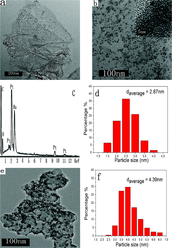 | ||
| Fig. 1 (a) and (b) TEM images of PtRu/FGSs, the inset is the HRTEM image of metallic particles on FGSs. (c) The EDS spectrum of PtRu/FGSs, (d) metallic particle size distribution of PtRu/FGSs, (e) a TEM image of PtRu/C, (f) metallic particle size distribution of PtRu/C. | ||
Fig. 1d and f show the histograms of the particle size of the PtRu nanoparticles on the different supporting materials (FGSs and carbon black). The size distribution of the PtRu particles on FGSs was in the range of 1.8–4.0 nm, with an average size of 2.87 nm (based on 200 nanoparticles). With respect to methanol electrooxidation of carbon-based PtRu catalysts, the optimal particle size with high catalytic performance is about 3 nm.43 The high-resolution TEM image (HRTEM) of PtRu/FGSs shows the oriented and ordered lattice fringes for metal nanoparticles (Fig. 1b), which corresponds to Pt fcc lattice. That is, the face-centered cubic crystal structure of Pt was found in PtRu particles. By contrast, the distribution of the PtRu nanoparticles on carbon black (Vulcan XC-72) was not as uniform as those on FGSs and some metallic nanoparticles on carbon black were agglomerated (Fig. 1e). An appreciably larger particle size (average particle size 4.39 nm in the range of 2.3–6.8 nm) was found on carbon black. The EDS analysis indicated that 19.9 wt% Pt and 10.6 wt% Ru were loaded on carbon black.
The XRD patterns of functionalized graphene sheets and the as-synthesized PtRu/FGSs composites are shown in Fig. 2. The broad peak located at about 25° could be assigned to the C (002) diffraction peak associated with the graphite-like structure (FGSs in Fig. 2a). That is, GO was partly reduced to graphene, and the conjugated sp2-hybridized carbon network has been re-established during the thermal reduction process (Fig. S1 in the supporting information shows the XRD pattern of GO†). In the case of the PtRu/FGSs composites, it is notable that the intensity of the (002) diffraction peak became weak. That is, the restacking of FGSs was prevented by the attached PtRu nanoparticles. The other four diffraction peaks, characteristic of the face centered cubic (fcc) crystalline Pt, correspond to the planes (111), (200), (220) and (311). These XRD patterns revealed the dominant feature of the disordered single-phase structures for the alloy catalyst. These diffraction peaks were shifted to slightly higher 2θ values,44 which indicated that Ru was partially dissolved in the Pt fcc lattice.45,46 It is worthwhile to note the lack of diffraction peaks characteristic of Pt or Ru oxides, which suggests that the precursors were mainly converted into metallic nanoparticles.
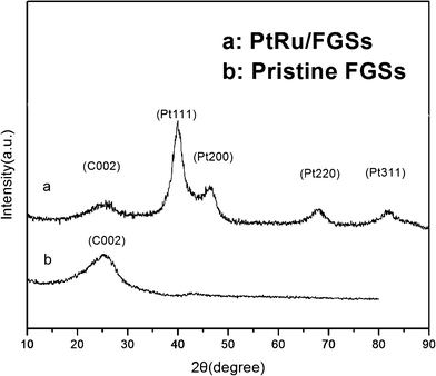 | ||
| Fig. 2 XRD patterns of (a) PtRu/FGSs; (b) FGSs. | ||
XPS analysis was performed to exactly detect the covalent state of various species in the PtRu/FGSs composites. The XPS atomic composition of FGSs showed a C/O ratio of 19![[thin space (1/6-em)]](https://www.rsc.org/images/entities/char_2009.gif) :
:![[thin space (1/6-em)]](https://www.rsc.org/images/entities/char_2009.gif) 1 after the thermal treatment, indicating that the functionalized graphene sheets possess highly hydrophobic surfaces due to the removal of oxygen-containing groups. The survey XPS spectrum of the PtRu/FGSs composites was shown in Fig. 3a. The presence of C, O, Pt and Ru could be detected in the composites, in agreement with the EDS analysis. The spectrum of Pt 4f consisted of three pairs of doublets (shown in Fig. 4b). The most intense peaks at the binding energies of 71.5 eV (Pt 4f7/2) and 74.8 eV (Pt 4f5/2) maintained an area ratio near 4
1 after the thermal treatment, indicating that the functionalized graphene sheets possess highly hydrophobic surfaces due to the removal of oxygen-containing groups. The survey XPS spectrum of the PtRu/FGSs composites was shown in Fig. 3a. The presence of C, O, Pt and Ru could be detected in the composites, in agreement with the EDS analysis. The spectrum of Pt 4f consisted of three pairs of doublets (shown in Fig. 4b). The most intense peaks at the binding energies of 71.5 eV (Pt 4f7/2) and 74.8 eV (Pt 4f5/2) maintained an area ratio near 4![[thin space (1/6-em)]](https://www.rsc.org/images/entities/char_2009.gif) :
:![[thin space (1/6-em)]](https://www.rsc.org/images/entities/char_2009.gif) 3 as expected theoretically for pure Pt (71.20 eV of Pt 4f7/2 and 74.53 eV of Pt 4f5/2).47 The other two weaker doublets could be attributed to Pt2+ in the form of PtO or Pt(OH)2 and Pt4+, possibly in the form of PtO2.48–50 The spectrum of Pt 4f suggests that metallic Pt(0) is the predominant species in the composites.
3 as expected theoretically for pure Pt (71.20 eV of Pt 4f7/2 and 74.53 eV of Pt 4f5/2).47 The other two weaker doublets could be attributed to Pt2+ in the form of PtO or Pt(OH)2 and Pt4+, possibly in the form of PtO2.48–50 The spectrum of Pt 4f suggests that metallic Pt(0) is the predominant species in the composites.
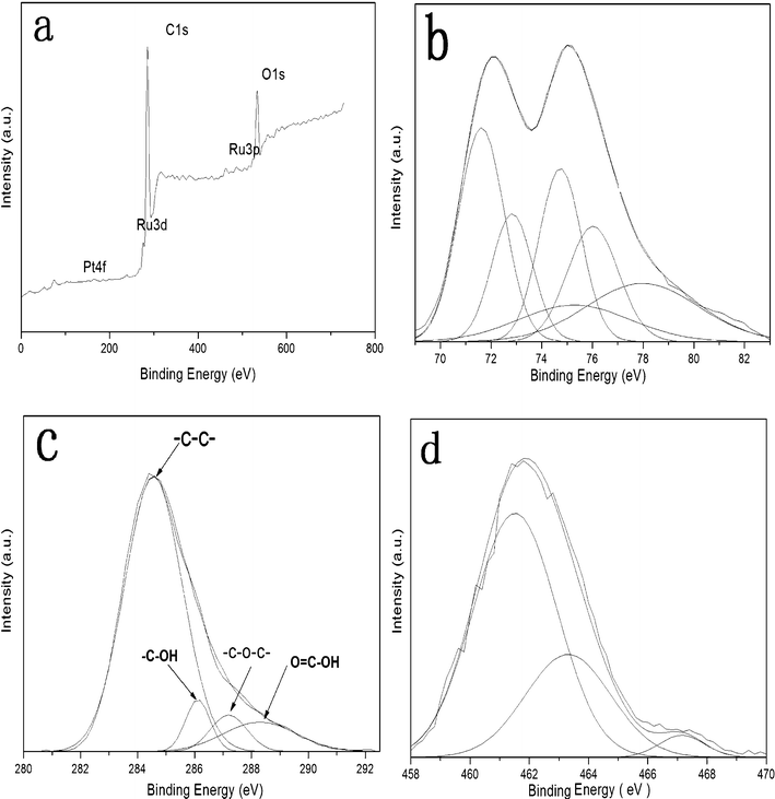 | ||
| Fig. 3 XPS spectra of PtRu/FGSs: (a) the survey spectrum, (b) Pt4f spectrum, (c) C1s spectrum and (d) Ru3p spectrum. | ||
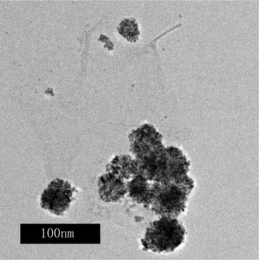 | ||
| Fig. 4 A TEM image of the PtRu/FGSs synthesized in the absence of SC CO2. | ||
The C 1s spectrum of the PtRu/FGSs composite is shown in Fig. 3c. The analysis of the C 1s spectrum indicated that a small number of oxygen-containing functional groups (–C–OH, –C–O–C– and –COOH) remained after thermal treatment, consistent with Schniepp’s investigation.22 As seen from the survey XPS spectrum, the C 1s peak of the carbon support at about 284.6 eV entirely covered the Ru 3d3/2 signal and partially overlapped with the Ru 3d5/2. Therefore, an accurate estimation of Ru oxidation state is not possible at this binding energy value. However, the peak at about 280 eV in the tail of the large C 1s peak could be qualitatively attributed to zero-valent Ru.51 The Ru 3p spectrum was used to analyze the Ru oxidation state (Fig. 3d). The main Ru 3p3/2 peak was deconvoluted into three distinguishable peaks at 461.4, 463.3 and 467.1 eV, which are characteristic of Ru (0), RuO2 and RuO2·xH2O, respectively.52 The relative integration areas of the peaks show that the large fraction of Ru is in the metallic state. The presence of metal oxides could be ascribed to the slight oxidation of nanoparticles upon exposure to air.
To elucidate the role of SC CO2 for the uniform dispersion of the PtRu nanoparticles on graphene surfaces, a composite was prepared using H2PtCl6 and RuCl3 as precursors without the presence of CO2. As shown in Fig. 4, the PtRu nanoparticles were agglomerated and unevenly distributed on FGSs. It is well known that SCFs possess unique properties, such as low viscosity, rapid diffusion and near zero surface tension.8,33 In our experiment, FGSs were first suspended in a methanol–water solution of H2PtCl6 and RuCl3. Then, CO2 was charged into the vessel up to 6.5 MPa at a temperature of 35 °C. As the temperature and pressure were increased, the FGSs could be wetted easily as a result of zero surface tension and high diffusivity of the SCF, thus facilitating the metallic precursors to reach the surfaces of FGSs and be adsorbed on the carbon substrate. At a higher temperature, the absorbed H2PtCl6 and RuCl3 were reduced by methanol. PtRu nucleated on the surfaces of FGSs and grew into nanoparticles, forming nanoparticle-containing composites. These metal particles disrupted the regular layer stacking of FGSs.
3.2 Electrocatalytic activity of the PtRu/FGSs electrode toward the oxidation of methanol
Fig. 5a compares the cyclic voltammograms of the PtRu/FGSs and PtRu/C catalysts for methanol electrooxidation in an N2-saturated solution of 0.5 M H2SO4 and 1 M CH3OH at room temperature (Fig. S2 and S3 show the calculated mass and surface area specific activities of the PtRu nanoparticles supported on FGSs and carbon black†). Table 1 displayed the methanol oxidation (forward and reverse) peak current density (IF and IR), the calculated mass specific activity and surface area specific activity (normalized with respect to the electrochemically active surface area ECSA shown in Fig. S3†), as well as the ratio of the forward anodic peak current density to the reverse anodic peak current density (IF/IR) of the PtRu/FGSs and PtRu/C catalysts. The mass specific activity of the PtRu nanoparticles supported on FGSs for the electrooxidation of methanol was 205.7 mA per mg Pt, which was 76.4% larger than that (116.6 mA per mg Pt) of the PtRu nanoparticles supported on carbon black. As depicted in Fig. 5b (CVs of PtRu/FGSs), there were notable changes in the potential cycles over time. At the first cycle, a lower peak current density and lower peak potential was observed in the forward scan and there was no peak during the reverse potential scan (attributed to the removal of CO and other residual carbonaceous species formed in the forward scan). With the increasing cycle number, the reverse anodic peak potentials emerged. Both the forward and reverse anodic peak potentials shifted more positively and the peak current densities increased. At the 25th cycle, the forward peak potential was located at about 0.66 V and a reverse peak centered at 0.40 V. This phenomenon may result from the leaching of ruthenium during the cycling of the electrode between the oxidizing and reducing potentials.31 Finally, the cyclic voltammogram of the catalyst was found to be similar to that of pure Pt. This phenomenon is in accordance with previous reports8 and was also observed in PtRu/C.53 The magnitude of the methanol oxidation peak current density is directly proportional to the amount of methanol oxidized at the electrode. At the PtRu/FGSs electrode, the peak current density obtained from the forward CV scan (the 25th cycle) was substantially larger than that of the PtRu/C (the 25th cycle), revealing that functionalized graphene sheets play an important role in enhancing the catalytic efficiency of metal particles. These experimental results highlight the high activity of PtRu/FGSs for methanol oxidation, which may arise from the larger surface area of FGSs and more uniform distribution of ultrafine PtRu particles (Fig. 1).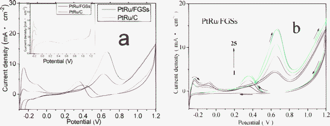 | ||
| Fig. 5 (a) Cyclic voltammograms (CVs) of the PtRu/FGSs and PtRu/C electrodes for the 25th cycle in the mix solution of 1 M CH3OH and 0.5 M H2SO4 at a scan rate of 50 mV s−1 (the inset shows CVs of the PtRu/FGSs and PtRu/C electrodes in 0.5 M H2SO4 solution without methanol). (b) CVs of PtRu/FGSs for the 1st, 5th, 10th, 15th, 20th, 25th cycle in the mix solution of 1 M CH3OH and 0.5 M H2SO4 at a scan rate of 50 mV s−1. | ||
| Catalyst | Forward sweep | Reverse sweep | I F/IR | ||||
|---|---|---|---|---|---|---|---|
| I F (mA cm−2) | J Fspec.(mass) (mA mg−1(Pt)) | J Fspec (surface area) (μA cm−2) | Potential (V) | I R (mA cm−2) | Potential (V) | ||
| a All data were obtained on the basis of the 25th cycle of cyclic voltammograms at a scan rate of 50 mV s−1. | |||||||
| PtRu/FGSs | 14.05 | 205.7 | 508.4 | 0.66 | 2.99 | 0.40 | 4.70 |
| PtRu/C | 8.21 | 116.6 | 397.3 | 0.62 | 4.08 | 0.35 | 2.10 |
The resistance to poison caused by adsorbed intermediates is another crucial concern for the catalysts from the viewpoint of application. Generally, the ratio of the forward anodic peak current (IF) to the reverse anodic peak current (IR) is used to describe the catalyst tolerance to the accumulation of CO and other carbonaceous species. A low ratio indicates poor oxidation of methanol to carbon dioxide during the anodic scan and excessive accumulation of carbonaceous residues on the catalyst surface. The ratio was calculated to be 4.70 for PtRu/FGSs at the 25th cycle, which was much larger than that (2.10) for PtRu/C. The higher IF/IR value indicated that the intermediate carbonaceous species could be more completely oxidized to carbon dioxide at the PtRu/FGSs electrode.
The long-term cycle stabilities of the PtRu/FGSs and PtRu/C electrodes for methanol oxidation were also studied, The forward peak currents on PtRu/FGSs and PtRu/C were measured as a function of the number of cycles and the results are shown in Fig. 6. In the case of PtRu/FGSs, the peak current remained almost constant from the 25th cycle to the 95th cycle after the initial increase. The peak current started to decrease gradually after the 95 cycles of potential scan. Using the current density measured after the 25th cycle as the reference, the anodic peak current of the 1000th cycle was about 76.4% of that measured at the 25th cycle. In the case of PtRu/C, a poorer stability was observed. The peak current started to decrease quickly after 25 cycles. The peak current of the 1000th cycle was 36.9% of the current density measured at the 25th cycle. The observations imply that the PtRu/FGSs catalyst possesses significantly enhanced long-term cycle stability for methanol oxidation compared to the PtRu/C catalyst.
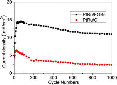 | ||
| Fig. 6 Long-term cycle stabilities of the PtRu/FGSs and PtRu/C electrodes in the mix solution of 1 M CH3OH and 0.5 M H2SO4 at a scan rate of 50 mV s−1. | ||
Chronoamperometric experiments were carried out to observe the stability and possible poisoning of the catalysts under continuous operation. Fig. 7 showed the evaluation of the catalytic activity and stability of the PtRu/FGSs and PtRu/C electrodes with respect to time. In the initial period, the current density decreased for both catalysts due to the formation of intermediate carbonaceous species. During the whole time, the current density of methanol oxidation at the PtRu/FGSs electrode was substantially higher than that at the PtRu/C electrode, although the current decay with time was observed in both samples. PtRu/FGSs exhibited higher catalytic activity and better stability for methanol oxidation than PtRu/C.
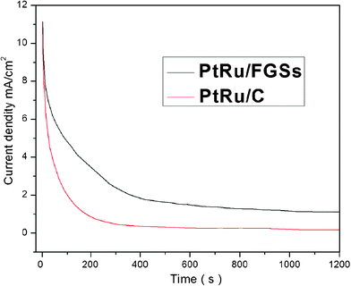 | ||
| Fig. 7 Current–time curves of PtRu/FGSs and PtRu/C at 0.6 V for 1200 s in the mix solution of 1 M CH3OH and 0.5 M H2SO4 solution saturated by N2 at room temperature. | ||
The mechanism of PtRu electrocatalysts for methanol oxidation could be explained by the so-called bifunctional mechanism suggested by Watanabe and Motoo.54 Although many carbonaceous species are involved in this process, it is widely accepted that the most abundant one is chemisorbed CO.53 OH species produced in water discharge reaction are preferentially chemisorbed on the Ru sites. The role of ruthenium is to dissociate water to form adsorbed OH species Ru–OH (eqn (1)), which then reacts with adsorbed CO other residual carbonaceous species on neighboring Pt sites to generate CO2 (eqn (2)):
| Ru + H2O→Ru–OH + H+ + e− | (1) |
| Ru–OH + Pt–COads→Ru + Pt + CO2↑ + H+ + e− | (2) |
The FGSs as a carbon support have a larger surface area and enable better dispersion of the PtRu nanoparticles than carbon black (Vulcan XC-72). Consequently, more catalytic Pt surface centers are available for methanol oxidation. In comparison with carbon black, the use of FGSs indeed significantly enhances the catalytic activity and stability of the PtRu particles for methanol oxidation. These experimental results indicate that FGSs behave as an effective catalytic support and the PtRu/FGS composites prepared in SC CO2 show good promise for fuel cell applications.
4 Conclusions
By using a facile, effective and environmentally benign SC CO2 method, ultrafine platinum and ruthenium metallic particles were evenly decorated on the hydrophobic surfaces of functionalized graphene sheets. The unique properties of SCFs enable the uniform deposition of ultrafine bimetallic catalysts on functionalized graphene sheets. PtRu/FGSs showed considerably better electrocatalytic performance for methanol oxidation than PtRu/carbon black owing to the uniform dispersion of nanosized metallic particles on the large surface area graphene sheets. The results presented in this paper demonstrate that the SCF synthetic route is a robust strategy for the fabrication of metallic electrocatalysts based on graphene and suggested the use of the electrocatalysts as promising candidates for the development of direct methanol fuel cells.Acknowledgements
The work was funded in part by the National Natural Science Foundation of China (No. 51073082 and 50943026), the Scientific Research Foundation for the Returned Overseas Chinese Scholars, the International Science and Technology Cooperation Program of China (2012DG42100), Qingdao Municipal Science and Technology Program, Basic Research Project (12-1-4-3-(7)-jch and 12-1-4-3-(25)-jch), Chongqing Key Laboratory of Micro/Nano Materials Engineering and Technology (open project KFJJ1202), MOE Key Laboratory of Organosilicon Chemistry and Material Technology of Ministry of Education (open project YJG2010-02) (Hangzhou Normal University), State Key Laboratory of Chemical Resource Engineering (open project CRE-2012-C-204) (Beijing University of Chemical Engineering), MOE Key Laboratory of Molecular Engineering of Polymers (Fudan University) and the Natural Science Foundation of Shandong Province (ZR2012EMM003).References
- K. S. Novoselov, A. K. Geim, S. V. Morozov, D. Jiang, M. I. Katsnelson, I. V. Grigorieva, S. V. Dubonos and A. A. Firsov, Nature, 2005, 438, 197–200 CrossRef CAS.
- K. S. Novoselov, A. K. Geim, S. V. Morozov, D. Jiang, Y. Zhang, S. V. Dubonos, I. V. Grigorieva and A. A. Firsov, Science, 2004, 306, 666–669 CrossRef CAS.
- K. S. Novoselov, D. Jiang, F. Schedin, T. J. Booth, V. V. Khotkevich, S. V. Morozov and A. K. Geim, Proc. Natl. Acad. Sci. U. S. A., 2005, 102, 10451–10453 CrossRef CAS.
- C. Berger, Z. Song, X. Li, X. Wu, N. Brown, C. Naud, D. Mayou, T. Li, J. Hass, A. N. Marchenkov, E. H. Conrad, P. N. First and W. A. de Heer, Science, 2006, 312, 1191–1196 CrossRef CAS.
- A. K. Geim and K. S. Novoselov, Nat. Mater., 2007, 6, 183–191 CrossRef CAS.
- C. N. R. Rao, A. K. Sood, K. S. Subrahmanyam and A. Govindaraj, Angew. Chem., Int. Ed., 2009, 48, 7752–7777 CrossRef CAS.
- S. Stankovich, D. A. Dikin, D. Dommett, K. Kohlhaas, E. Zimney and E. Stach, Nature, 2006, 442, 282–286 CrossRef CAS.
- G. An, P. Yu, L. Mao, Z. Sun, Z. Liu, S. Miao, Z. Miao and K. Ding, Carbon, 2007, 45, 536–542 CrossRef CAS.
- K.-Y. Chan, J. Ding, J. Ren, S. Cheng and K. Y. Tsang, J. Mater. Chem., 2004, 14, 505–516 RSC.
- L. Dong, R. R. S. Gari, Z. Li, M. M. Craig and S. Hou, Carbon, 2010, 48, 781–787 CrossRef CAS.
- G. A. Olah, Angew. Chem., Int. Ed., 2005, 44, 2636–2639 CrossRef CAS.
- Y. Zhao, X. Yang, L. Zhan, S. Ou and J. Tian, J. Mater. Chem., 2011, 21, 4257–4263 RSC.
- S. Liu, J. Wang, J. Zeng, J. Ou, Z. Li, X. Liu and S. Yang, J. Power Sources, 2010, 195, 4628–4633 CrossRef CAS.
- B. Seger and P. V. Kamat, J. Phys. Chem. C, 2009, 113, 7990–7995 CAS.
- R. Kou, Y. Shao, D. Wang, M. H. Engelhard, J. H. Kwak, J. Wang, V. V. Viswanathan, C. Wang, Y. Lin, Y. Wang, I. A. Aksay and J. Liu, Electrochem. Commun., 2009, 11, 954–957 CrossRef CAS.
- C. Xu, X. Wang and J. Zhu, J. Phys. Chem. C, 2008, 112, 19841–19845 CAS.
- C. Nethravathi, E. A. Anumol, M. Rajamathi and N. Ravishankar, Nanoscale, 2011, 3, 569–571 RSC.
- R. K. Raman, A. K. Shukla, A. Gayen, M. S. Hegde, K. R. Priolkar, P. R. Sarode and S. Emura, J. Power Sources, 2006, 157, 45–55 CrossRef CAS.
- Y. Li, W. Gao, L. Ci, C. Wang and P. M. Ajayan, Carbon, 2010, 48, 1124–1130 CrossRef CAS.
- H. Hu, Y. Liu, Q. Wang, J. Zhao and Y. Liang, Mater. Lett., 2011, 65, 2582–2584 CrossRef CAS.
- M. J. McAllister, J.-L. Li, D. H. Adamson, H. C. Schniepp, A. A. Abdala, J. Liu, M. Herrera-Alonso, D. L. Milius, R. Car, R. K. Prud'homme and I. A. Aksay, Chem. Mater., 2007, 19, 4396–4404 CrossRef CAS.
- H. C. Schniepp, J.-L. Li, M. J. McAllister, H. Sai, M. Herrera-Alonso, D. H. Adamson, R. K. Prud'homme, R. Car, D. A. Saville and I. A. Aksay, J. Phys. Chem. B, 2006, 110, 8535–8539 CrossRef CAS.
- H. Hu and L. Yin, Mater. Lett., 2011, 65, 2582–2584 CrossRef CAS.
- Y. Si and E. T. Samulski, Nano Lett., 2008, 8, 1679–1682 CrossRef CAS.
- Y. Li, X. Fan, J. Qi, J. Ji, S. Wang, G. Zhang and F. Zhang, Mater. Res. Bull., 2010, 45, 1413–1418 CrossRef CAS.
- S. Guo, S. Dong and E. Wang, ACS Nano, 2009, 4, 547–555 CrossRef.
- Y. Si and E. T. Samulski, Chem. Mater., 2008, 20, 6792–6797 CrossRef CAS.
- Z. Liu and B. Han, Adv. Mater., 2009, 21, 825–829 CrossRef CAS.
- Z. Liu, J. Phys.: Conf. Ser., 2009, 165, 012081 CrossRef.
- X.-R. Ye, Y. Lin, C. Wang, M. H. Engelhard, Y. Wang and C. M. Wai, J. Mater. Chem., 2004, 14, 908–913 RSC.
- Y. Lin and X. Cui, J. Phys. Chem. B, 2005, 109, 14410–14415 CrossRef CAS.
- Y. Lin, X. Cui, C. H. Yen and C. M. Wai, Langmuir, 2005, 21, 11474–11479 CrossRef CAS.
- Z. Liu, J. Y. Lee, M. Han, W. Chen and L. M. Gan, J. Mater. Chem., 2002, 12, 2453–2458 RSC.
- Z. Liu, X. Ling, X. Su and J. Y. Lee, J. Phys. Chem. B, 2004, 108, 8234–8240 CrossRef CAS.
- W. S. Hummers and R. E. Offeman, J. Am. Chem. Soc., 1958, 80, 1339–1339 CrossRef CAS.
- H. A. Becerril, J. Mao, Z. Liu, R. M. Stoltenberg, Z. Bao and Y. Chen, ACS Nano, 2008, 2, 463–470 CrossRef CAS.
- D. R. Dreyer, S. Park, C. W. Bielawski and R. S. Ruoff, Chem. Soc. Rev., 2010, 39, 228–240 RSC.
- L. Zhang, J. Liang, Y. Huang, Y. Ma, Y. Wang and Y. Chen, Carbon, 2009, 47, 3365–3368 CrossRef CAS.
- A. Muge, M. Cecilia, G. Cheng, L. Geunsik, C. Kyeongjae, C. Manish and C. Y. J, ACS Nano, 2010, 4, 5861–5868 CrossRef.
- H. K. Chae, D. Y. Siberio-Perez, J. Kim, Y. Go, M. Eddaoudi, A. J. Matzger, M. O'Keeffe and O. M. Yaghi, Nature, 2004, 427, 523–527 CrossRef CAS.
- H. A. Gasteiger, N. Markovic, P. N. Ross and E. J. Cairns, J. Phys. Chem., 1994, 98, 617–625 CrossRef CAS.
- Y. Xing, J. Phys. Chem. B, 2004, 108, 19255–19259 CrossRef CAS.
- Y. Takasu, H. Itaya, T. Iwazaki, R. Miyoshi, T. Ohnuma, W. Sugimoto and Y. Murakami, Chem. Commun., 2001, 341–342 RSC.
- D. Chu and S. Gilman, J. Electrochem. Soc., 1996, 143, 6 CrossRef.
- L. W.Z, L. CH, W. J. Zhou, Q. J. S., Z. ZH and G. Q. Sun, J. Phys. Chem. B, 2003, 107, 6292–6299 CrossRef.
- T. Wu, Y. Lin and C. Liao, Carbon, 2005, 43, 734 CrossRef CAS.
- J. F. Moulder, W. F. Stickle, P. E. Sobol and K. D. Bomben, Handbook of X-Ray Photoelectron Spectroscopy, 1992 Search PubMed.
- X. Li and I.-M. Hsing, Electrochim. Acta, 2006, 52, 1358–1365 CrossRef CAS.
- D.-S. Yang, K.-S. k. Sim, H.-D. Kwen and S.-H. Choi, J. Nanomat., 2011, 2011, 1–8 Search PubMed.
- T. Frelink, W. Visscher, A. P. Cox and J. A. R. Van Veen, Electrochim. Acta, 1995, 40, 1537–1543 CrossRef CAS.
- W. Xu, T. Lu, C. Liu and W. Xing, J. Phys. Chem. B, 2005, 109, 14325–14330 CrossRef CAS.
- A. S. Aricò, V. Baglio, A. Di Blasi, E. Modica, P. L. Antonucci and V. Antonucci, J. Electroanal. Chem., 2003, 557, 167–176 CrossRef.
- W. L. Holstein and H. D. Rosenfeld, J. Phys. Chem. B, 2004, 109, 2176–2186 CrossRef.
- M. Watanabe, Y. Zhu, H. Igarashi and H. Uchida, Electrochem., 2000, 68, 244–251 CAS.
Footnote |
| † Electronic Supplementary Information (ESI) available. See DOI: 10.1039/c2ra00027j/ |
| This journal is © The Royal Society of Chemistry 2012 |
