Photoluminescence and phosphorescence from MCM-48 nanoparticle-embedded composite nanofibers prepared by electrospinning
Huijun
Qin
ab,
Minru
Liang
ab,
Xiaoshi
Zhang
ab,
Yi
Zhao
ab,
Qiwen
Pan
ab,
Zhijun
Ma
ab,
Guoping
Dong
*ab and
Jianrong
Qiu
ab
aState Key Laboratory of Luminescent Materials and Devices, South China University of Technology, Guangzhou, 510640, China. E-mail: dgp@scut.edu.cn; Fax: 86 20 87114204; Tel: 86 20 87114235
bInstitute of Optical Communication Materials, South China University of Technology, Guangzhou, 510640, China
First published on 17th September 2012
Abstract
MCM-48 nanoparticle-embedded polymer nanofibers (NPNFs) were prepared from the PVP solution containing MCM-48 nanoparticles (NPs) by the electrospinning technique. X-ray diffraction (XRD), scanning electron microscopy (SEM) and energy-dispersive X-ray spectrometry (EDS) were used to characterize the composition and morphology of electrospun nanofibers. The results showed that the average diameter of MCM-48 NPNFs was about 500 nm. Photoluminescence (PL) and phosphorescence properties were investigated by fluorescence spectrofluorometer. MCM-48 NPNFs exhibited a bright blue-green emission at ∼420 nm, followed by a long-lifetime blue-green phosphorescence at ∼480 nm, which can be fitted by a bi-exponential decay process with lifetimes of 3.24 s and 1.22 s at room temperature. The triplet-to-singlet transition is responsible for the blue-green emission around 420 nm of the MCM materials, while the phosphorescence at ∼480 nm is probably due to the oxygen-related vacancies on the surface, which act as a capture trap.
1. Introduction
In the past few years, MCM mesoporous materials, such as MCM-41 and MCM-48, have received considerable attention since the discovery of the M41S family by Mobil workers in 1992.1 The primary properties of these mesoporous materials are high pore volume, large surface area, and narrow distribution of pore sizes. These new materials have come into notice owing to their potential applications in catalysis, adsorption, gas separation, and ion exchange.2–8 What's more, MCM mesoporous materials can also act as host materials as a result of mesoporous structures. Various nano-materials, like semiconductor quantum dots (QDs), magnetic nanoparticles, and luminescent nanocrystals have been stuffed inside the mesoporous structure to make a melioration of structure and functions, which may be widely used in various areas.9–11 It is very important to explore the optical properties of MCM materials both from scientific and technological points of view. Since the first observation of intrinsic photoluminescence (PL) in amorphous SiO2,12 many researchers have concentrated on the PL properties of silica materials.13–21 The PL of mesoporous siliceous MCM-41 has been studied already,22–30 while little attention has been paid to MCM-48. Furthermore, these materials are usually synthesized by a liquid–crystal mechanism. Nowadays, one dimensional (1D) nanomaterials (nanofibers, nanowires, nanorods, nanotubes, etc.), due to their transverse nanoscale, large surface to volume ratio, unique optical, electrical, mechanical and magnetic properties, have been applied in biomedical materials, energy, environment, optical and electrical devices. Among various preparation methods, electrospinning, as one of the most convenient and effective methods to prepare 1D nanomaterials, has received great attention in the past decade.31–39 However, it is difficult to directly fabricate MCM-48 nanofibers with excellent PL properties by electrospinning. If we can synthesize MCM-48 nanoparticles (NPs) and incorporate them into polymer electrospun nanofibers, these composite nanofibers are expected to possess the advantages of both MCM-48 nanoparticles and polymer nanofiber hosts, which will widen their potential applications in optical waveguides, sensors, displays, etc.In the present work, we utilize sol–gel and solvothermal synthesis to prepare MCM-48 NPs, and then MCM-48 nanoparticle-embedded polymer nanofibers (NPNFs) were fabricated through the electrospinning technique. The blue-green PL and phosphorescence properties of MCM-48 NPNFs were investigated, and the luminescence mechanisms were also discussed in detail.
2. Experimental and characterizations
Preparation of MCM-48 nanoparticles
MCM-48 NPs were synthesized by the method reported previously,40 using surfactant cetyltrimethylammonium bromide (CTAB), tetraethyl orthosilicate (TEOS) and sodium hydroxide (NaOH) purchased from Sinopharm Chemical Reagent (SCR) Co., Ltd (Shanghai, China) as the raw materials. Siliceous MCM-48 was synthesized according to the following procedure: 5.25 g CTAB and 0.72 g NaOH were added to the 35.1 mL deionized water with stirring until the solution became uniform and clear. Then 6.25 g TEOS was added into the above solution with stirring for 3 h to obtain a homogeneous gel with a designed CTAB![[thin space (1/6-em)]](https://www.rsc.org/images/entities/char_2009.gif) :
:![[thin space (1/6-em)]](https://www.rsc.org/images/entities/char_2009.gif) TEOS
TEOS![[thin space (1/6-em)]](https://www.rsc.org/images/entities/char_2009.gif) :
:![[thin space (1/6-em)]](https://www.rsc.org/images/entities/char_2009.gif) NaOH
NaOH![[thin space (1/6-em)]](https://www.rsc.org/images/entities/char_2009.gif) :
:![[thin space (1/6-em)]](https://www.rsc.org/images/entities/char_2009.gif) H2O composition of 0.48
H2O composition of 0.48![[thin space (1/6-em)]](https://www.rsc.org/images/entities/char_2009.gif) :
:![[thin space (1/6-em)]](https://www.rsc.org/images/entities/char_2009.gif) 1
1![[thin space (1/6-em)]](https://www.rsc.org/images/entities/char_2009.gif) :
:![[thin space (1/6-em)]](https://www.rsc.org/images/entities/char_2009.gif) 0.6
0.6![[thin space (1/6-em)]](https://www.rsc.org/images/entities/char_2009.gif) :
:![[thin space (1/6-em)]](https://www.rsc.org/images/entities/char_2009.gif) 65 (in mol%). Gel mixtures were reacted at 110 °C for 24 h in PTFE-lined stainless steel autoclaves, and then the precipitated products were filtered, washed with distilled water three times and heated in a drying oven at 60 °C. Finally, MCM-48 NPs were obtained to prepare MCM-48 NPNFs.
65 (in mol%). Gel mixtures were reacted at 110 °C for 24 h in PTFE-lined stainless steel autoclaves, and then the precipitated products were filtered, washed with distilled water three times and heated in a drying oven at 60 °C. Finally, MCM-48 NPs were obtained to prepare MCM-48 NPNFs.
Preparation of MCM-48 nanoparticle-embedded nanofibers
Firstly, 4 g PVP (polyethylene pyrrolidone, 30 K) was dissolved in 10 mL ethanol with stirring for 3 h at room temperature to obtain a homogeneous PVP solution. Then ∼0.1 g MCM-48 NPs was added into the above solution with stirring to get a homogeneous solution. This homogeneous system was obtained as the precursor solution for electrospinning.41 The syringe which contained precursor solution was placed in the syringe pump with a feeding rate of 0.6 mL h−1. The positive pole of the DC high-voltage power supply was connected to the syringe needle and the working voltage was fixed as 20 kV. Fibers were collected on the grounded aluminium collector 12 cm away and the rotation speed of the metal roller was fixed at 200 rpm. After electrospinning for 5 h, the as-prepared MCM-48 NPNFs were peeled off for structure and optical property characterizations.Characterizations
The obtained MCM-48 NPs and NPNFs were collected for structure and property characterizations. A scanning electron microscope (SEM, S4700) equipped with an energy-dispersive X-ray spectrometer (EDS) was used to observe the morphology, size and composition of NPs and NPNFs. After ultrasonically dispersing in alcohol for 10 min, the NPs were salvaged with copper grids. The transmission electron microscopy (TEM) and selected area electron diffraction (SAED) images were obtained with a JSM-2010F TEM. X-ray diffraction (XRD) patterns were obtained to identify components using a Rigaku D/MAX X-ray diffractometer with Cu Kα radiation, and a resolution of ±0.02°. The photoluminescence (PL) spectra and the decay lifetime of electrospun nanofibers were measured on a fluorescence spectrofluorometer (JASCO FP-6500). The resolution of PL spectra is ±0.5 nm, while the error of lifetimes fitted by the bi-exponential decay process is within ±0.01 s. The electrospun nanofibers were first excited with 360 nm light for 5 min. Then the decay curve after stopping the illumination was recorded immediately.3. Results and discussions
Fig. 1(a) shows the SEM image of MCM-48 NPs. As can be seen from the graph, the size of the MCM-48 NPs is uniform. By randomly choosing a number of nanoparticles, the TEM image is shown in Fig. 1(b), which indicates the average diameter is about 100 nm. The inset of Fig. 1(b) illustrates the SAED pattern of the MCM-48 NPs. A center spot with dispersive haloes can be observed clearly, which indicates that the MCM-48 nanoparticles are constituted of amorphous silica. Fig. 1(c) shows the SEM image of MCM-48 NPNFs. The average diameter of nanofibers is about 500 nm and the length is greater than 1 cm. In particular, the surface of nanofibers is smooth and no serious breakage is observed in the SEM image. The EDS spectrum of MCM-48 NPNFs is also illustrated in Fig. 1(d); the peaks assigned to as-designed elements (i.e. Si, O) are clearly observed. Besides the C peak resulting from the conductive C films coated on the sample in the course of EDS measurement, a few other elements (i.e. Na , Br) are detected in the spectrum, which result from the residual NaOH and CTAB reagents.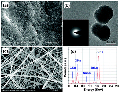 | ||
| Fig. 1 (a) SEM image of MCM-48NPs. (b) TEM image of MCM-48 NPs, and inset shows SAED pattern corresponding to the nanoparticle in Fig. 1(b). (c) SEM image of MCM-48 NPNFs. (d) EDS spectrum of MCM-48 NPNFs. | ||
Fig. 2 shows XRD patterns of MCM-48 NPs and MCM-48 NPNFs. The curves show clearly the characteristics of MCM-48 materials for each sample. The broad peaks and shoulders at 2θ = 22.5°, 25.8°, 29.1°, 32.3°, 36.8° and 43.6° are in agreement with the diffraction of (101), (110), (111), (102), (200), (211) crystal faces of tetragonal SiO2 phase (JCPDF: 82-1235). Due to the obvious broadband characteristic of diffraction peaks, it can be deduced that the as-prepared MCM-48 NPs are amorphous silica, which further confirms the SAED result in Fig. 1(b). Owing to the remarkable broadening of the dominant diffraction peak at 2θ = 22.5°, the XRD patterns exhibit a peak envelope between 2θ = 10–50°. On the background of broad peak envelope, all the diffraction peaks are ascribed to the SiO2 phase. No additional diffraction peak of other phases is detected in MCM-48 NPs, which indicates that the sample is pure amorphous silica. For the XRD pattern (Fig. 2(b)) of MCM-48 NPNFs, another strong peak is shown at the lower range (2θ = 10.8°), which is assigned to a characteristic peak of PVP.41,42
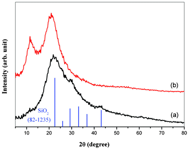 | ||
| Fig. 2 XRD patterns of MCM-48 materials: (a) MCM-48 NPs; (b) MCM-48 NPNFs. | ||
Fig. 3 shows the excitation and emission spectra of MCM-48 NPs and MCM-48 NPNFs. The corresponding excitation spectra include double broad bands from 220 nm to 360 nm with peaks at 245 nm and 360 nm, which probably originated from the transition of defect levels in amorphous SiO2. When the MCM-48 NPs and MCM-48 NPNFs are excited by a 360 nm ultraviolet (UV) lamp, an intense emission band maximum at 420 nm (blue-green emission) are clearly observed. There is no obvious difference between the emission band of MCM NPs and NPNFs. In many cases, the PL of SiO2 based materials originates from these structural defects, such as oxygen-related defects, non-bridging oxygen hole centers, etc.22,24 In order to explain the emission mechanism of SiO2 based materials, researchers have founded several models, such as E′ centers, peroxyl radicals,22 twofold-coordinated silicon centers,25,28–30 Si–OH surface complex,26 hydrogen-related species,43 and self-trapped excitions.44 The blue-green emission could be attributed to the triplet-to-singlet process (Si02: 3B1 → 1A1 transition),44 which responded to process 4 in the Fig. 5. When MCM-48 NPNFs are excited by UV light, the electrons in the ground state are excited to the triplet state (process 1). Then electrons are released to the ground state and blue-green emission is observed.
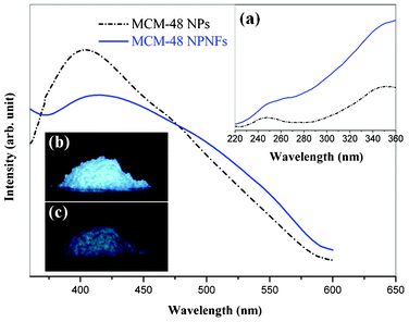 | ||
| Fig. 3 Emission spectra of MCM-48 NPs (dotted line) and MCM-48 NPNFs (solid line). Inset (a) shows the excitation spectra monitored at 420 nm. Inset (b) and (c) show the digital photographs of MCM-48 NPs upon (b) and after (c) the removal of irradiating light of a 360 nm UV lamp, respectively. | ||
Fig. 4 shows emission spectra of MCM-48 NPNFs with the extension of time after removal of the irradiating light (turn-off time), which illustrates an obvious red shift of the emission band. When the turn-off time was 0 ms, the maximum of the emission band is about 420 nm, which is coincident with the result measured under UV excitation in Fig. 3. When the turn-off time reached 25 ms, the emission band was red shifted with a peak at 480 nm. With the turn-off time was extended from 25 ms to 100 ms, the emission peak stayed at 480 nm. Only a slight narrowing of emission band is observed in the spectra. Further extension of turn-off time had almost no influence on the emission band, and the emission peak was ultimately concentrated at 480 nm. The spectroscopic evolution characteristic of MCM-48 NPNFs after removal of the 365 nm irradiating light is similar to that of MCM-48 NPs (not listed). The inset of Fig. 4 shows the normalized phosphorescence decay curve for the 480 nm emission of MCM-48 NPNFs. The MCM-48 NPNFs are illuminated by a 360 nm UV lamp for 5 min. Then the excitation resource is removed and the phosphorescence decay curve is measured immediately. The phosphorescence decay curve is a bi-exponential decay process, which contains an initially fast decay process and a slow decay process. The bi-exponential decay curve can be fitted by the following equation: I(t) = A1exp(−t/τ1) + A2exp(−t/τ2). From the bi-exponential fitting of the phosphorescence decay curve, it can be calculated that the fast and slow decay lifetimes are 1.22 s and 3.24 s, respectively. Both of these values were similar to those of MCM-48 NPs (1.29 s and 3.28 s).
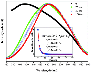 | ||
| Fig. 4 Emission spectra of MCM-48 NPNFs for different times after removal of the irradiating light with a 360 nm UV lamp. Inset shows the normalized phosphorescence decay curve for the 480 nm emission of MCM-48 NPNFs. | ||
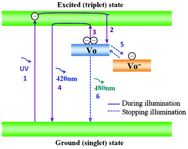 | ||
| Fig. 5 Schematic phosphorescence mechanism of MCM-48 NPNFs. | ||
It is generally recognized that phosphorescence emission is a process of trapping and thermal de-trapping of excited electrons at intrinsic or extrinsic defect centers.45,46 Herein, according to Lee and Kinoshita's theoretical foundation,30,47 red shift and phosphorescence emission can be explained as follows (see Fig. 5): in the MCM-48 NPNFs system, under excitation by UV light, the electrons in the ground state are populated in the excited state (process 1), which will relax into the VO defect level and be trapped by this electron-trapping level. The VO defect level can capture one or two electrons and become VO− center and VO center levels, respectively (process 2). The thermal energy at ambient temperatures causes the de-trapping of the trapped electrons of the VO center directly into the excited triplet states (process 3). Then electrons are released to the ground state with a 420 nm emission (process 4). At the same time, the trapped electrons in the VO− center was released to the VO center (process 5) and returned to the ground state with a 480 nm emission (process 6). When the MCM-48 NPNFs were under excitation by UV light, process 1–4 are in the leading position so that the emission peak is about 420 nm. However, after the removal of irradiating light, due to the slight energy difference between VO− center and VO center levels, process 5 and 6 will become the predominant processes. These will result in the red shift of emission band from 420 nm to 480 nm and the 480 nm phosphorescence emission in Fig. 4.
Conclusions
MCM-48 NPNFs with a diameter of ∼500 nm were prepared by electrospinning with MCM-48 NPs as precursor. XRD patterns confirmed that the nanofibers were amorphous silica. PL properties of MCM-48 materials (MCM-48 NPs and MCM-48 NPNFs) were investigated. A blue-green PL emission and red shift were observed in MCM-48 NPNFs. Mechanism of phosphorescence and red shift was also discussed in the present work. Shallow defect level, as an electron-trapping and de-trapping level, played a vital role in the phosphorescence emission. The results presented here are expected to be useful for clarifying the nature of phosphorescence emission in MCM materials and to be of practical applications in bio-labels, photoelectronic devices and photocatalysts.Acknowledgements
This work was financially supported by the National Natural Science Foundation of China (Grants no. 51102096, 51132004, 51072054, 51072060), Fundamental Research Funds for the Central Universities (Grants no. 2011ZB0001, 2012ZB0003, 2011ZZ0001, 2011ZP0002), Guangdong Natural Science Foundation (Grant no. S2011030001349, 1045106410104887), and UIRT of Guangdong Province.References
- C. T. Kresge, M. E. Leonowics, W. J. Roth, J. C. Vartuli and J. S. Beck, Nature, 1992, 359, 710 CrossRef CAS.
- S. Polarz and B. Smarsly, J. Nanosci. Nanotechnol., 2002, 2, 581 CrossRef CAS.
- U. Ciesla and F. Schuth, Microporous Mesoporous Mater., 1999, 27, 131 CrossRef CAS.
- A. Sayari and P. Liu, Microporous Mesoporous Mater., 1997, 12, 149 CAS.
- P. Selvam, S. K. Bhatia and C. G. Sonwane, Ind. Eng. Chem. Res., 2001, 40, 3237 CrossRef CAS.
- X. S. Zhao and G. Q. Lu, J. Phys. Chem. B, 1998, 102, 556 Search PubMed.
- E. Stathatos, T. Petrova and P. Lianos, Langmuir, 2001, 17, 5025 CrossRef CAS.
- Y. Kim, J. R. Choi, M. Yoon, A. Furube, T. Asahi and H. Masuhara, J. Phys. Chem. B, 2001, 105, 8513 CrossRef CAS.
- L. Chen, P. J. Klar, W. Heimbrodt, F. J. Brieler, M. Froba and H. A. Krug, J. Appl. Phys., 2003, 93, 1326 CrossRef CAS.
- Y. S. Tang, S. Cai, G. Jin, J. Duan, K. L. Wang and H. M. Soyez, Appl. Phys. Lett., 1997, 71, 2448 CrossRef CAS.
- A. Govindaaraj, M. Nath and M. Eswaramoorthy, Chem. Phys. Lett., 2000, 317, 35 CrossRef.
- C. M. Gee and M. Kastner, Phys. Rev. Lett., 1979, 42, 1765 CrossRef CAS.
- R. Tohmon, Y. Shimogaichi, H. Mizuno and Y. Ohki, Phys. Rev. Lett., 1989, 62, 1388 CrossRef CAS.
- H. Nishikawa, T. Shiroyama, R. Nakamura and Y. Ohki, Phys. Rev. B: Condens. Matter, 1992, 45, 586 CrossRef CAS.
- T. Kanashima, R. Nagayoshi and M. Okuyama, J. Appl. Phys., 1993, 74, 5742 CrossRef CAS.
- M. S. El-Shall, S. Li, T. Turkki, D. Graiver, U. C. Pernisz and M. I. Baraton, J. Phys. Chem., 1995, 99, 17805 CrossRef CAS.
- J. Lin and K. Baerner, Mater. Lett., 2000, 46, 86 CrossRef CAS.
- C. K. Lin, M. Yu, Z. Y. Cheng, C. M. Zhang, Q. G. Meng and J. Lin, Inorg. Chem., 2008, 47, 49 CrossRef CAS.
- Z. Y. Hou, C. M. Zhang, C. X. Li, Z. H. Xu, Z. Y. Cheng, G. G. Li, W. X. Wang, C. Peng and J. Lin, Chem.–Eur. J., 2010, 16, 14513 CrossRef CAS.
- D. Y. Kong, C. M. Zhang, Z. H. Xu, G. G. Li, Z. Y. Hou and J. Lin, J. Colloid Interface Sci., 2010, 352, 278 CrossRef CAS.
- J. Zhang and J. Lin, Microporous Mesoporous Mater., 2004, 75, 115 CrossRef CAS.
- M. E. Gimon-Kinsel, K. Groothuis and K. J. Balkus, Microporous Mesoporous Mater., 1998, 20, 67 CrossRef CAS.
- J. L. Shen, P. L. Chen, Y. C. Lee, P. W. Cheng and C. F. Cheng, Solid State Commun., 2002, 122, 65 CrossRef CAS.
- Y. D. Glinka, A. S. Zyubin, A. M. Mebel, S. H. Lin, L. P. Hwang and Y. T. Chen, Chem. Phys. Lett., 2002, 358, 180 CrossRef CAS.
- Y. Zhang, F. Phillipp, G. W. Meng, L. D. Zhang and C. H. Ye, J. Appl. Phys., 2000, 88, 2196 Search PubMed.
- H. J. Chang, Y. F. Chen, H. P. Lin and C. Y. Mou, Appl. Phys. Lett., 2001, 78, 3791 CrossRef CAS.
- Y. D. Glinka, S. H. Lin, L. P. Hwang and Y. T. Chen, J. Phys. Chem. B, 2000, 104, 8652 CrossRef CAS.
- J. L. Shen, Y. C. Lee, Y. L. Liu, P. W. Cheng and C. F. Cheng, J. Phys.: Condens. Matter, 2003, 15, L297 CrossRef CAS.
- Y. C. Lee, Y. L. Liu, W. Z. Lee, C. K. Wang, J. L. Shen, P. W. Cheng, C. F. Cheng and T. Y. Lin, Phys. Status Solidi A, 2004, 201, 3188 CrossRef CAS.
- Y. C. Lee, Y. L. Liu, C. K. Wang, J. L. Shen, P. W. Cheng, C. F. Cheng, C. H. Ko and T. Y. Lin, J. Lumin., 2005, 113, 258 CrossRef CAS.
- D. Li and Y. N. Xia, Adv. Mater., 2004, 16, 1151 CrossRef CAS.
- A. Greiner and J. H. Wendorff, Angew. Chem., Int. Ed., 2007, 46, 5670 CrossRef CAS.
- D. H. Reneker and A. L. Yarin, Polymer, 2008, 49, 2387 CrossRef CAS.
- X. F. Lu, C. Wang and Y. Wei, Small, 2009, 5, 2349 CrossRef CAS.
- Z. Y. Hou, G. G. Li, H. Z. Lian and J. Lin, J. Mater. Chem., 2012, 22, 5254 RSC.
- H. W. Song, H. Q. Yu, G. H. Pan, X. Bai, B. Dong, X. T. Zhang and S. K. Hark, Chem. Mater., 2008, 20, 4762 CrossRef CAS.
- G. G. Li, Z. Y. Hou, C. Peng, W. X. Wang, Z. Y. Cheng, C. X. Li, H. Z. Lian and J. Lin, Adv. Funct. Mater., 2010, 20, 3446 CrossRef CAS.
- G. P. Dong, X. D. Xiao, M. Y. Peng, Z. J. Ma, S. Ye, D. D. Chen, H. J. Qin, G. L. Deng, Q. M. Liang and J. R. Qiu, RSC Adv., 2012, 2, 2773 RSC.
- G. P. Dong, X. D. Xiao, Y. Z. Chi, B. Qian, X. F. Liu, Z. J. Ma, E. Wu, H. P. Zeng, D. P. Chen and J. R. Qiu, J. Mater. Chem., 2010, 20, 1587 RSC.
- L. Z. Wang, J. L. Shi, W. H. Zhang, M. L. Ruan, J. Yu and D. S. Yan, Chem. Mater., 1999, 11, 3015 CrossRef CAS.
- G. P. Dong, X. F. Liu, X. D. Xiao, B. Qian, J. Ruan, S. Ye, H. C. Yang, D. P. Chen and J. R. Qiu, Nanotechnology, 2009, 20, 055707 CrossRef.
- G. P. Dong, X. F. Liu, X. D. Xiao, Q. Zhang, G. Lin, Z. J. Ma, D. P. Chen and J. R. Qiu, Electrochem. Solid-State Lett., 2009, 12, 53 CrossRef.
- Y. D. Glinka, S. H. Lin, L. P. Wang and Y. T. Chen, J. Phys. Chem. B, 2000, 104, 8652 CrossRef CAS.
- Y. C. Lee, Y. L. Liu, J. L. Shen, I. J. Hsu, P. W. Cheng, C. F. Cheng and C. H. Ko, J. Non-Cryst. Solids, 2004, 341, 16 CrossRef CAS.
- F. Clabau, X. Rocquefelte, S. Jobic, P. Deniard, M. H. Whangbo, A. Garcia and T. Le Mercier, Chem. Mater., 2005, 17, 3904 CrossRef CAS.
- G. P. Dong, X. D. Xiao, L. L. Zhang, Z. J. Ma, X. Bao, M. Y. Peng, Q. Y. Zhang and J. R. Qiu, J. Mater. Chem., 2011, 21, 2194 RSC.
- T. Kinoshita, M. Yamazaki, H. Kawazoe and H. Hosono, J. Appl. Phys., 1999, 86, 3729 CrossRef CAS.
| This journal is © The Royal Society of Chemistry 2012 |
