Carbon nanotube-conducting polymer composite wires formed by fountain pen growth (FPG) route†
Seung Kwon
Seol
*,
Won Suk
Chang
,
Daeho
Kim
and
Sunshin
Jung
Advanced Medical Device Research Center, Korea Electrotechnology Research Institute (KERI), Ansan, 426-910, Korea. E-mail: skseol@keri.re.kr; Fax: +82-31-8040-4199; Tel: +82-31-8040-4182
First published on 7th August 2012
Abstract
We demonstrate the three dimensional (3D) growth of multiwalled carbon nanotube (MWNT)–PEDOT![[thin space (1/6-em)]](https://www.rsc.org/images/entities/char_2009.gif) :
:![[thin space (1/6-em)]](https://www.rsc.org/images/entities/char_2009.gif) PSS composite microwires by a fountain pen growth (FPG) route. The electrical conductivity of the grown composite wire is improved by enhancing the electrical network of entrapped MWNTs formed in the PEDOT
PSS composite microwires by a fountain pen growth (FPG) route. The electrical conductivity of the grown composite wire is improved by enhancing the electrical network of entrapped MWNTs formed in the PEDOT![[thin space (1/6-em)]](https://www.rsc.org/images/entities/char_2009.gif) :
:![[thin space (1/6-em)]](https://www.rsc.org/images/entities/char_2009.gif) PSS matrix.
PSS matrix.
Conducting polymers, such as polypyrrole (PPy), poly(3,4-ethylenedioxythiophene)
![[thin space (1/6-em)]](https://www.rsc.org/images/entities/char_2009.gif) :
:![[thin space (1/6-em)]](https://www.rsc.org/images/entities/char_2009.gif) poly(styrenesulfonate) (PEDOT
poly(styrenesulfonate) (PEDOT![[thin space (1/6-em)]](https://www.rsc.org/images/entities/char_2009.gif) :
:![[thin space (1/6-em)]](https://www.rsc.org/images/entities/char_2009.gif) PSS) and polyaniline (PANI), are very interesting materials because they have the electrical properties of a metal and the mechanical properties—flexibility, toughness and elasticity—of a conventional polymer.1,2 However, in spite of persistent efforts over the last decade, the conductivity and mechanical strength of conducting polymers still need to be improved to facilitate their use in practical applications.
PSS) and polyaniline (PANI), are very interesting materials because they have the electrical properties of a metal and the mechanical properties—flexibility, toughness and elasticity—of a conventional polymer.1,2 However, in spite of persistent efforts over the last decade, the conductivity and mechanical strength of conducting polymers still need to be improved to facilitate their use in practical applications.
One strategy for enhancing the properties of conducting polymers is to add other materials. In particular, carbon nanotubes (CNTs), which have high conductivity, high strength and large aspect ratios, are promising additive candidates.3,4 The CNTs that are added to the host conducting polymer matrix contribute to improving the electrical and mechanical properties of the conducting polymer by mutual interactions between CNTs and the conducting polymer.5–7 Due to their distinguished properties, CNT-conducting polymer composites have a significant potential for use in applications such as solar cells, field effect transistors, sensors and actuators.8–11 Their advanced applications often require the formation of patterned structures on the micrometre and nanometre length scales.12–16 However, most fabrication methods are limited to two-dimensional (2D) planar patterning of thin composite films or low-aspect-ratio structures, whereas three-dimensional (3D) patterning is essential.
Here, using a fountain pen growth (FPG) route,17 we successfully fabricate 3D microwires composed of multiwalled carbon nanotube (MWNT)–PEDOT![[thin space (1/6-em)]](https://www.rsc.org/images/entities/char_2009.gif) :
:![[thin space (1/6-em)]](https://www.rsc.org/images/entities/char_2009.gif) PSS composites with a high aspect ratio and tunable electrical properties. The electrical conductivity of the grown composite wire is improved by an increase of the MWNT concentration in the growth solution, resulting from an enhancement of the electrical networks of the entrapped MWNTs formed in the PEDOT
PSS composites with a high aspect ratio and tunable electrical properties. The electrical conductivity of the grown composite wire is improved by an increase of the MWNT concentration in the growth solution, resulting from an enhancement of the electrical networks of the entrapped MWNTs formed in the PEDOT![[thin space (1/6-em)]](https://www.rsc.org/images/entities/char_2009.gif) :
:![[thin space (1/6-em)]](https://www.rsc.org/images/entities/char_2009.gif) PSS matrix.
PSS matrix.
To prepare the growth solution (ink), PEDOT![[thin space (1/6-em)]](https://www.rsc.org/images/entities/char_2009.gif) :
:![[thin space (1/6-em)]](https://www.rsc.org/images/entities/char_2009.gif) PSS (1.3 wt.% in H2O, Aldrich) was used as the host material. Multiwalled carbon nanotubes (MWNTs) were employed as an additive, and the concentration varied from 0.07 to 0.62 wt.%. The sizes of the MWNTs ranged from 15 to 20 nm in diameter and had lengths up to 5 μm. The SDS (sodium dodecyl sulfate)-coated MWNTs dispersed in H2O were purchased from Bmstech. The as-purchased MWNT solution was mixed with PEDOT
PSS (1.3 wt.% in H2O, Aldrich) was used as the host material. Multiwalled carbon nanotubes (MWNTs) were employed as an additive, and the concentration varied from 0.07 to 0.62 wt.%. The sizes of the MWNTs ranged from 15 to 20 nm in diameter and had lengths up to 5 μm. The SDS (sodium dodecyl sulfate)-coated MWNTs dispersed in H2O were purchased from Bmstech. The as-purchased MWNT solution was mixed with PEDOT![[thin space (1/6-em)]](https://www.rsc.org/images/entities/char_2009.gif) :
:![[thin space (1/6-em)]](https://www.rsc.org/images/entities/char_2009.gif) PSS solution using only ultrasonication. The MWNT was dispersed well and the MWNT–PEDOT
PSS solution using only ultrasonication. The MWNT was dispersed well and the MWNT–PEDOT![[thin space (1/6-em)]](https://www.rsc.org/images/entities/char_2009.gif) :
:![[thin space (1/6-em)]](https://www.rsc.org/images/entities/char_2009.gif) PSS solution remained without sediment for more than a week. Glass micropipettes with an opening diameter of 10 μm (fountain pen) were obtained with a pipette-puller (P-97, Sutter Instrument). The micropipette was filled with the growth solution. The substrates were platinum-coated silicon wafers for freestanding MWNT–PEDOT
PSS solution remained without sediment for more than a week. Glass micropipettes with an opening diameter of 10 μm (fountain pen) were obtained with a pipette-puller (P-97, Sutter Instrument). The micropipette was filled with the growth solution. The substrates were platinum-coated silicon wafers for freestanding MWNT–PEDOT![[thin space (1/6-em)]](https://www.rsc.org/images/entities/char_2009.gif) :
:![[thin space (1/6-em)]](https://www.rsc.org/images/entities/char_2009.gif) PSS composite wires and gold patterns with 30 μm gaps for wire bridging. The position and the pulling speed of the micropipette were accurately controlled with 3-axis stepping motors with positioning accuracies of 250 nm. The growth process was observed in situ by a high-resolution monitoring system consisting of an optical lens and a CCD camera (Spot RT Xplore).
PSS composite wires and gold patterns with 30 μm gaps for wire bridging. The position and the pulling speed of the micropipette were accurately controlled with 3-axis stepping motors with positioning accuracies of 250 nm. The growth process was observed in situ by a high-resolution monitoring system consisting of an optical lens and a CCD camera (Spot RT Xplore).
The microscopic characteristics of the grown wires were analyzed using field emission scanning electron microscopy (FE-SEM, MIRA3). Current–voltage (I–V) characteristics were measured by a two-point measurement with a Keithley 2612A instrument at room temperature.
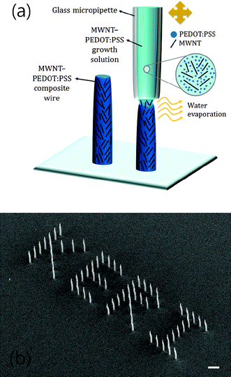
A schematic illustration of the FPG route for the growth of the MWNT–PEDOT![[thin space (1/6-em)]](https://www.rsc.org/images/entities/char_2009.gif) :
:![[thin space (1/6-em)]](https://www.rsc.org/images/entities/char_2009.gif) PSS composite wire is shown in Fig. 1(a). The composite wire is grown by pulling the glass micropipette filled with the growth solution consisting of colloidal MWNTs in PEDOT
PSS composite wire is shown in Fig. 1(a). The composite wire is grown by pulling the glass micropipette filled with the growth solution consisting of colloidal MWNTs in PEDOT![[thin space (1/6-em)]](https://www.rsc.org/images/entities/char_2009.gif) :
:![[thin space (1/6-em)]](https://www.rsc.org/images/entities/char_2009.gif) PSS solution. When the micropipette touches the substrate, a meniscus of the growth solution is created outside its opening. As the micropipette is pulled away by 250 nm (stepwise pulling, pulling speed of 0.5 μm s−1), the meniscus is stretched, and its cross section reaches 10 μm, which is similar to the opening diameter of the micropipette. During the pulling process, the meniscus is solidified rapidly by solvent (water) evaporation,17 forming the MWNT–PEDOT
PSS solution. When the micropipette touches the substrate, a meniscus of the growth solution is created outside its opening. As the micropipette is pulled away by 250 nm (stepwise pulling, pulling speed of 0.5 μm s−1), the meniscus is stretched, and its cross section reaches 10 μm, which is similar to the opening diameter of the micropipette. During the pulling process, the meniscus is solidified rapidly by solvent (water) evaporation,17 forming the MWNT–PEDOT![[thin space (1/6-em)]](https://www.rsc.org/images/entities/char_2009.gif) :
:![[thin space (1/6-em)]](https://www.rsc.org/images/entities/char_2009.gif) PSS composite wire. We can easily imagine that a large surface area-to-volume ratio of the micro-meniscus leads to enhanced evaporation of the water molecules by increasing the amount of the exposed area in contact with air. Fig. 1(b) shows a “KERI” pattern of MWNT–PEDOT
PSS composite wire. We can easily imagine that a large surface area-to-volume ratio of the micro-meniscus leads to enhanced evaporation of the water molecules by increasing the amount of the exposed area in contact with air. Fig. 1(b) shows a “KERI” pattern of MWNT–PEDOT![[thin space (1/6-em)]](https://www.rsc.org/images/entities/char_2009.gif) :
:![[thin space (1/6-em)]](https://www.rsc.org/images/entities/char_2009.gif) PSS composite wires formed by precise positioning of the micropipette. For electrical and mechanical stability, the composite wire is annealed for 60 min at 110 °C after the growth. The wire diameter in Fig. 1(b) is reduced from 10 to 8 μm by 20% shrinkage of the PEDOT
PSS composite wires formed by precise positioning of the micropipette. For electrical and mechanical stability, the composite wire is annealed for 60 min at 110 °C after the growth. The wire diameter in Fig. 1(b) is reduced from 10 to 8 μm by 20% shrinkage of the PEDOT![[thin space (1/6-em)]](https://www.rsc.org/images/entities/char_2009.gif) :
:![[thin space (1/6-em)]](https://www.rsc.org/images/entities/char_2009.gif) PSS matrix due to additional water evaporation during the annealing process.
PSS matrix due to additional water evaporation during the annealing process.
 | ||
Fig. 1 (a) A schematic illustration of the fountain pen growth (FPG) route for MWNT–PEDOT![[thin space (1/6-em)]](https://www.rsc.org/images/entities/char_2009.gif) : :![[thin space (1/6-em)]](https://www.rsc.org/images/entities/char_2009.gif) PSS composite wire growth. (b) A FE-SEM image of a “KERI” pattern of MWNT–PEDOT PSS composite wire growth. (b) A FE-SEM image of a “KERI” pattern of MWNT–PEDOT![[thin space (1/6-em)]](https://www.rsc.org/images/entities/char_2009.gif) : :![[thin space (1/6-em)]](https://www.rsc.org/images/entities/char_2009.gif) PSS composite wires (scale bar: 50 μm). PSS composite wires (scale bar: 50 μm). | ||
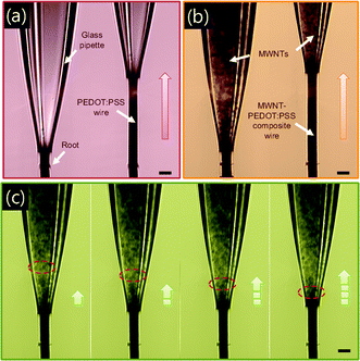
Fig. 2 presents optical micrographs of the FPG route monitored by real-time optical microscopy. We can observe the growth process of the PEDOT![[thin space (1/6-em)]](https://www.rsc.org/images/entities/char_2009.gif) :
:![[thin space (1/6-em)]](https://www.rsc.org/images/entities/char_2009.gif) PSS wire (Fig. 2(a)) and the MWNT (0.62 wt.%)–PEDOT
PSS wire (Fig. 2(a)) and the MWNT (0.62 wt.%)–PEDOT![[thin space (1/6-em)]](https://www.rsc.org/images/entities/char_2009.gif) :
:![[thin space (1/6-em)]](https://www.rsc.org/images/entities/char_2009.gif) PSS composite wire (Fig. 2(b) and 2(c)). In contrast to the inside brightness of the micropipette in Fig. 2(a), the shaded image of Fig. 2(b) is attributed to dispersed MWNTs and their clusters in the PEDOT
PSS composite wire (Fig. 2(b) and 2(c)). In contrast to the inside brightness of the micropipette in Fig. 2(a), the shaded image of Fig. 2(b) is attributed to dispersed MWNTs and their clusters in the PEDOT![[thin space (1/6-em)]](https://www.rsc.org/images/entities/char_2009.gif) :
:![[thin space (1/6-em)]](https://www.rsc.org/images/entities/char_2009.gif) PSS solution. The optical micrograph sequence of Fig. 2(c) shows the flow of MWNTs in the micropipette during the growth. The MWNT suspension is one of yield stress fluids which require a threshold stress before they begin to flow.18 In the FPG route, sufficient stress is applied by micropipette pulling, enabling MWNTs to flow in the micropipette. As the micropipette is pulled away, the MWNTs (see red circles in Fig. 2(c)) flow down and converge at the opening of the micropipette. The MWNT–PEDOT
PSS solution. The optical micrograph sequence of Fig. 2(c) shows the flow of MWNTs in the micropipette during the growth. The MWNT suspension is one of yield stress fluids which require a threshold stress before they begin to flow.18 In the FPG route, sufficient stress is applied by micropipette pulling, enabling MWNTs to flow in the micropipette. As the micropipette is pulled away, the MWNTs (see red circles in Fig. 2(c)) flow down and converge at the opening of the micropipette. The MWNT–PEDOT![[thin space (1/6-em)]](https://www.rsc.org/images/entities/char_2009.gif) :
:![[thin space (1/6-em)]](https://www.rsc.org/images/entities/char_2009.gif) PSS composite wire with MWNT networks is formed by a release of the PEDOT
PSS composite wire with MWNT networks is formed by a release of the PEDOT![[thin space (1/6-em)]](https://www.rsc.org/images/entities/char_2009.gif) :
:![[thin space (1/6-em)]](https://www.rsc.org/images/entities/char_2009.gif) PSS solution with converging MWNTs at the micropipette opening. The formation kinetics of MWNT networks is thought to involve a cooperative MWNT-cluster or cluster-cluster aggregation during the wire growth.
PSS solution with converging MWNTs at the micropipette opening. The formation kinetics of MWNT networks is thought to involve a cooperative MWNT-cluster or cluster-cluster aggregation during the wire growth.
 | ||
Fig. 2 Optical micrographs of the FPG process. (a) PEDOT![[thin space (1/6-em)]](https://www.rsc.org/images/entities/char_2009.gif) : :![[thin space (1/6-em)]](https://www.rsc.org/images/entities/char_2009.gif) PSS wire. (b) MWNT (0.62 wt.%)–PEDOT PSS wire. (b) MWNT (0.62 wt.%)–PEDOT![[thin space (1/6-em)]](https://www.rsc.org/images/entities/char_2009.gif) : :![[thin space (1/6-em)]](https://www.rsc.org/images/entities/char_2009.gif) PSS composite wire. The shading in the glass micropipette is due to dispersed MWNTs or their clusters. (c) A MWNT (0.62 wt.%)–PEDOT PSS composite wire. The shading in the glass micropipette is due to dispersed MWNTs or their clusters. (c) A MWNT (0.62 wt.%)–PEDOT![[thin space (1/6-em)]](https://www.rsc.org/images/entities/char_2009.gif) : :![[thin space (1/6-em)]](https://www.rsc.org/images/entities/char_2009.gif) PSS composite wire with MWNT networks is formed by the release of the PEDOT PSS composite wire with MWNT networks is formed by the release of the PEDOT![[thin space (1/6-em)]](https://www.rsc.org/images/entities/char_2009.gif) : :![[thin space (1/6-em)]](https://www.rsc.org/images/entities/char_2009.gif) PSS solution with converging MWNTs at the opening of the micropipette (scale bar: 10 μm). PSS solution with converging MWNTs at the opening of the micropipette (scale bar: 10 μm). | ||
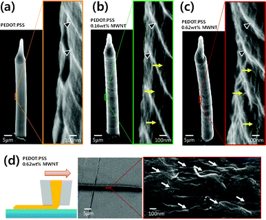
We investigated the morphological change of the grown wire with respect to the MWNT concentration. The PEDOT![[thin space (1/6-em)]](https://www.rsc.org/images/entities/char_2009.gif) :
:![[thin space (1/6-em)]](https://www.rsc.org/images/entities/char_2009.gif) PSS wire exhibits a smooth surface, as observed in the FE-SEM image of Fig. 3(a). The wrinkles indicated by black arrow heads in the enlarged images are formed by the 250 nm stepwise pulling of the micropipette. When 0.16 wt.% MWNT is added to the growth solution, hairline protrusions on the surface of the grown wire, indicated by yellow arrows, are caused by MWNTs entrapped in the PEDOT
PSS wire exhibits a smooth surface, as observed in the FE-SEM image of Fig. 3(a). The wrinkles indicated by black arrow heads in the enlarged images are formed by the 250 nm stepwise pulling of the micropipette. When 0.16 wt.% MWNT is added to the growth solution, hairline protrusions on the surface of the grown wire, indicated by yellow arrows, are caused by MWNTs entrapped in the PEDOT![[thin space (1/6-em)]](https://www.rsc.org/images/entities/char_2009.gif) :
:![[thin space (1/6-em)]](https://www.rsc.org/images/entities/char_2009.gif) PSS matrix (see Fig. 3(b)). In Fig. 3(c), the 0.62 wt.% loading of MWNTs leads to an increase in the number of protrusions, forming a bumpy surface on the grown wire. Using the FPG route, we can fabricate not only a freestanding vertical wire but also a horizontal line. Fig. 3(d) shows a schematic illustration of the growth route and an FE-SEM image of the grown MWNT (0.62 wt.%)–PEDOT
PSS matrix (see Fig. 3(b)). In Fig. 3(c), the 0.62 wt.% loading of MWNTs leads to an increase in the number of protrusions, forming a bumpy surface on the grown wire. Using the FPG route, we can fabricate not only a freestanding vertical wire but also a horizontal line. Fig. 3(d) shows a schematic illustration of the growth route and an FE-SEM image of the grown MWNT (0.62 wt.%)–PEDOT![[thin space (1/6-em)]](https://www.rsc.org/images/entities/char_2009.gif) :
:![[thin space (1/6-em)]](https://www.rsc.org/images/entities/char_2009.gif) PSS composite line. In the enlarged FE-SEM image of the composite line, entrapped MWNTs and their networks in the PEDOT
PSS composite line. In the enlarged FE-SEM image of the composite line, entrapped MWNTs and their networks in the PEDOT![[thin space (1/6-em)]](https://www.rsc.org/images/entities/char_2009.gif) :
:![[thin space (1/6-em)]](https://www.rsc.org/images/entities/char_2009.gif) PSS matrix (indicated by white arrows) are clearly shown.
PSS matrix (indicated by white arrows) are clearly shown.
 | ||
Fig. 3 (a–c) FE-SEM images of grown wires. The wrinkles indicated by black arrow heads in the enlarged images are formed by the 250 nm stepwise pulling of the micropipette. Yellow arrows indicate entrapped MWNTs in the PEDOT![[thin space (1/6-em)]](https://www.rsc.org/images/entities/char_2009.gif) : :![[thin space (1/6-em)]](https://www.rsc.org/images/entities/char_2009.gif) PSS matrix. (a) PEDOT wire. (b) MWNT (0.16 wt.%)–PEDOT-PSS composite wire. (c) MWNT (0.62 wt.%)–PEDOT-PSS composite wire. (d) Horizontal growth of the MWNT (0.62 wt.%)–PEDOT PSS matrix. (a) PEDOT wire. (b) MWNT (0.16 wt.%)–PEDOT-PSS composite wire. (c) MWNT (0.62 wt.%)–PEDOT-PSS composite wire. (d) Horizontal growth of the MWNT (0.62 wt.%)–PEDOT![[thin space (1/6-em)]](https://www.rsc.org/images/entities/char_2009.gif) : :![[thin space (1/6-em)]](https://www.rsc.org/images/entities/char_2009.gif) PSS composite line. Schematic illustration of the growth route (left) and FE-SEM image of the grown composite line (right). White arrows indicate entrapped MWNTs and their networks in the PEDOT PSS composite line. Schematic illustration of the growth route (left) and FE-SEM image of the grown composite line (right). White arrows indicate entrapped MWNTs and their networks in the PEDOT![[thin space (1/6-em)]](https://www.rsc.org/images/entities/char_2009.gif) : :![[thin space (1/6-em)]](https://www.rsc.org/images/entities/char_2009.gif) PSS matrix. PSS matrix. | ||
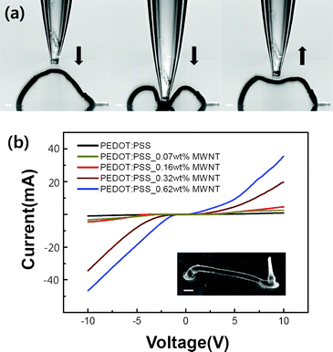
Fig. 4(a) consists of sequential optical images of the bending process of the MWNT (0.62 wt.%)–PEDOT![[thin space (1/6-em)]](https://www.rsc.org/images/entities/char_2009.gif) :
:![[thin space (1/6-em)]](https://www.rsc.org/images/entities/char_2009.gif) PSS composite wire with an arched shape. The peak of the arch structure is pushed vertically by a precisely-controlled micropipette. When the peak becomes in contact with the substrate, the micropipette is moved upward and the shape of the arch structure is almost restored. This result shows that the grown wire is stable and even flexible. The MWNT network formed in the PEDOT
PSS composite wire with an arched shape. The peak of the arch structure is pushed vertically by a precisely-controlled micropipette. When the peak becomes in contact with the substrate, the micropipette is moved upward and the shape of the arch structure is almost restored. This result shows that the grown wire is stable and even flexible. The MWNT network formed in the PEDOT![[thin space (1/6-em)]](https://www.rsc.org/images/entities/char_2009.gif) :
:![[thin space (1/6-em)]](https://www.rsc.org/images/entities/char_2009.gif) PSS matrix contributes to improving the electrical conductivity of the grown wire. Fig. 4(b) displays the dependence of the electrical conductivity of the grown wire on the MWNT concentration. To analyze the I–V characteristics of the MWNT–PEDOT
PSS matrix contributes to improving the electrical conductivity of the grown wire. Fig. 4(b) displays the dependence of the electrical conductivity of the grown wire on the MWNT concentration. To analyze the I–V characteristics of the MWNT–PEDOT![[thin space (1/6-em)]](https://www.rsc.org/images/entities/char_2009.gif) :
:![[thin space (1/6-em)]](https://www.rsc.org/images/entities/char_2009.gif) PSS composite wire, the wire bridge was fabricated between two gold electrodes with a 30 μm gap by the FPG route. As the MWNT concentration in the grown solution increases, the conductivity of the grown wire is improved by enhancing the electron flow along the grown wire that results from an increase in the number of connection nodes in the formed MWNT network.
PSS composite wire, the wire bridge was fabricated between two gold electrodes with a 30 μm gap by the FPG route. As the MWNT concentration in the grown solution increases, the conductivity of the grown wire is improved by enhancing the electron flow along the grown wire that results from an increase in the number of connection nodes in the formed MWNT network.
 | ||
Fig. 4 (a) Sequential optical images of the bending process of the MWNT (0.62 wt.%)–PEDOT![[thin space (1/6-em)]](https://www.rsc.org/images/entities/char_2009.gif) : :![[thin space (1/6-em)]](https://www.rsc.org/images/entities/char_2009.gif) PSS composite wire with an arched shape. (b) Current–voltage (I–V) characteristics of the MWNT–PEDOT PSS composite wire with an arched shape. (b) Current–voltage (I–V) characteristics of the MWNT–PEDOT![[thin space (1/6-em)]](https://www.rsc.org/images/entities/char_2009.gif) : :![[thin space (1/6-em)]](https://www.rsc.org/images/entities/char_2009.gif) PSS composite wire. The electrical conductivity is changed with the MWNT concentration. The inset FE-SEM image shows a wire bridge formed between two gold electrodes (scale bar: 10 μm). PSS composite wire. The electrical conductivity is changed with the MWNT concentration. The inset FE-SEM image shows a wire bridge formed between two gold electrodes (scale bar: 10 μm). | ||
Conclusions
In summary, we successfully fabricated MWNT–PEDOT![[thin space (1/6-em)]](https://www.rsc.org/images/entities/char_2009.gif) :
:![[thin space (1/6-em)]](https://www.rsc.org/images/entities/char_2009.gif) PSS composite microwires with high aspect ratios and tunable electrical properties by a simple, inexpensive FPG route. The composite wire growth is based on guiding the meniscus of the growth solution of colloidal MWNTs in PEDOT
PSS composite microwires with high aspect ratios and tunable electrical properties by a simple, inexpensive FPG route. The composite wire growth is based on guiding the meniscus of the growth solution of colloidal MWNTs in PEDOT![[thin space (1/6-em)]](https://www.rsc.org/images/entities/char_2009.gif) :
:![[thin space (1/6-em)]](https://www.rsc.org/images/entities/char_2009.gif) PSS solution by pulling a glass micropipette during solidification of the meniscus caused by solvent evaporation. The electrical conductivity of the grown wire is modulated by adjusting the MWNT concentration in the growth solution. It is caused by the change in the electrical network formation of entrapped MWNTs in the PEDOT
PSS solution by pulling a glass micropipette during solidification of the meniscus caused by solvent evaporation. The electrical conductivity of the grown wire is modulated by adjusting the MWNT concentration in the growth solution. It is caused by the change in the electrical network formation of entrapped MWNTs in the PEDOT![[thin space (1/6-em)]](https://www.rsc.org/images/entities/char_2009.gif) :
:![[thin space (1/6-em)]](https://www.rsc.org/images/entities/char_2009.gif) PSS matrix. The practical cases presented here are only a few of the many examples of CNT-conducting polymer composite wires that the FPG route can fabricate by appropriate tuning of the growth parameters. This novel growth route is quite effective in producing conducting polymer micro- and nanowires with CNTs as additives.
PSS matrix. The practical cases presented here are only a few of the many examples of CNT-conducting polymer composite wires that the FPG route can fabricate by appropriate tuning of the growth parameters. This novel growth route is quite effective in producing conducting polymer micro- and nanowires with CNTs as additives.
Acknowledgements
This work was supported by a grant (Code No. 12-50-H0102-02) from the Primary Research Program of Korea Electrotechnology Research Institute (KERI), Republic of Korea.References
- A. G. MacDiarmid, Angew. Chem., Int. Ed., 2001, 40, 2581 CrossRef CAS.
- G. Gustafsson, Y. Cao, G. M. Treacy, F. Klavetter, N. Colaneri and A. J. Heeger, Nature, 1992, 357, 477 CrossRef CAS.
- S. Ijima, Nature, 1991, 354, 56 CrossRef.
- G. Z. Chen, M. S. P. Shaffer, D. Coleby, G. Dixon, W. Zhou, D. J. Fray and A. H. Windle, Adv. Mater., 2000, 12, 522 CrossRef CAS.
- T. M. Wu, Y. W. Lin and C. S. Liao, Carbon, 2005, 43, 734 CrossRef CAS.
- A. V. Kyrylyuk, M. C. Hermant, T. Schiling, B. Klumperman, C. E. Konig and P. Schoot, Nat. Nanotechnol., 2011, 6, 364 CrossRef CAS.
- C. Y. Wei, D. Srivastava and K. J. Cho, Nano Lett., 2002, 2, 647 CrossRef CAS.
- B. Fan, X. Mei, K. Sun and J. Ouyang, Appl. Phys. Lett., 2008, 93, 143103 CrossRef.
- D. J Yun, K. Hong, S. H. Kim, W. M. Yun, J. Y. Jang, W. S. Kwon, C. E. Park and S. W. Rhee, ACS Appl. Mater. Interfaces, 2011, 3, 43 Search PubMed.
- R. Mangu, S. Rajaputra and V. P. Singh, Nanotechnology, 2011, 22, 215502 CrossRef.
- G. M. Spinks, V. Mottaghitalab, M. Bahrami-Samani, P. G. Whitten and G. G. Wallace, Adv. Mater., 2006, 18, 637 CrossRef CAS.
- W. S. Beh, I. T. Kim, D. Qin, Y. Xia and G. M. Whitesides, Adv. Mater., 1999, 11, 1038 CrossRef CAS.
- F. Zhang, T. Nyberg and O. Inganäs, Nano Lett., 2002, 2, 1373 CrossRef CAS.
- J.-H. Lim and C. A. Mirkin, Adv. Mater., 2002, 14, 1474 CrossRef CAS.
- F. D. Benedetto, A. Camposeo, S. Pagliara, E. Mele, L. Persano, R. Stabile, R. Cingolani and D. Pisignano, Nat. Nanotechnol., 2008, 3, 614 CrossRef.
- X. Lu, C. Wang and Y. Wei, Small, 2009, 5, 2349 CrossRef CAS.
- J. T. Kim, S. K. Seol, J. Pyo, J. S. Lee, J. H. Je and G. Margaritondo, Adv. Mater., 2011, 23, 1968 CrossRef CAS.
- E. K. Hobbie and D. J. Fry, Phys. Rev. Lett., 2006, 97, 036101 CrossRef CAS.
Footnote |
| † Electronic Supplementary Information (ESI) available. See DOI: 10.1039/c2ra21076b |
| This journal is © The Royal Society of Chemistry 2012 |
