Synthesis of Ni–Mo and Co–Mo–Ni nano-sulfides and their stable catalysis on complicated full-ranged pyrolysis gasoline hydrorefinery†
Junhua
Zhu‡
,
Yuanlin
Cheng‡
,
Kangjian
Tang
*,
Limin
Wang
,
Siqin
Li
* and
Weimin
Yang
Shanghai Research Institute of Petrochemical Technology, SINOPEC, Shanghai, 201208, P. R. China. E-mail: tangkj.sshy@sinopec.com; li.sq@163.com; Fax: +86-21-68462283; Tel: +86-21-68462197-4212
First published on 20th August 2012
Abstract
A stable nano-sulfide composite catalyst was synthesized and developed to improve the catalysis of classic pyrolysis gasoline hydrorefinery, based on the rigorous requirement of practical full-ranged (FR) feedstock. Through controlling active components on shielded nanosubstrates, the developed nanocatalyst showed superior characteristics over 1000 h of catalytic test, such as 1) high dispersibility of active components, 2) ultrastability under high space velocity (SV) and complex feedstock conditions and 3) better anti-impurity ability.
Nanocomposite materials, functional materials based on their components' properties and nanosized synergy, have attracted great interest in recent years for their importance in a wide variety of applications,1 including nanocomposite catalysts,2 magnets,3 ceramics,4 polymers,5 nanocomposite light-emitting devices,6 membranes,7 carbon nanotube based materials8 organic–inorganic hybrid materials,1c,9 and bio-nanocomposite materials10etc. In the field of catalysis, nanocomposite catalysts offer a positive opportunity to improve catalytic efficiency. Their advantage lies in two aspects: one is the nanosized synergy, which helps to increase the surface area and activity of materials,11 the other is the development of new functions, which is based on the interacted synergy between composite components.12 Numerous methods have been developed to fabricate these kinds of materials, such as self-assemby3 sol–gel technique,13 CVD process,14 hydrothermal synthesis,15 coprecipitation,16 and electrochemical method.17 However, simple and low-cost methods that are suitable for industrial production of ultrastable nanocomposite catalysts still remain a big challenge.
Pyrolysis gasoline (Pygas) is one of the main by-products from stream cracking of naphtha in the ethylene industry. During the hydrogenation process, high value-added BTX (benzene, toluene and xylene) is extracted from Pygas (see the process on Chart 1).17 From the 1960s, Chevron, UOP, Shell, IFP, EXXON and Sinopec etc. incessantly brought out systemic devices (catalysts and equipment) for executing the extracting technique. During the hydrogenation process, pyrolysis gasoline hydrorefinery (PGHr)18 is the key, but also most complex, section, which saturates residual olefins19 and removes impurities such as sulfides, nitrides and oxides. Since it is under high pressure and high temperature, the superior catalysts for PGHr require not only high catalytic ability for hydrodesulfurization (HDS),20,21 hydrodenitrogenation (HDN)21etc., but also high stability to fulfill the requirement of long service life. Due to their practical and scientific significance, many fundamental studies on these catalysts have been carried out.22 In recent years, in order to increase the utilization of Pygas, the methods of imprinting full-ranged component (C5–C9+) and increasing SV under lower reaction temperature were mainly used. However, the feedstock of full-ranged component also introduced a much broader variety of sulfide and nitride contents or more impurities, which are very harmful to present catalysts (their activity and service life decrease very quickly, due to coking etc.). Besides, very high SV under low reaction temperature would induce incomplete hydrogenation, which would not meet the requirement of BTX quality. So, it is very important to make effective catalysts with high activity and stability under long-term service for the aforementioned full-ranged feedstock.
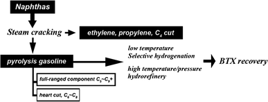 | ||
| Chart 1 Schematic process of hydrogenation for BTX recovery. | ||
As is known, the Co–Mo, Ni–Mo or Ni–W binary sulfides23 on porous substrate are the most applied and studied industrial catalysts for PGHr. The traits of PGHr can be described as follows. 1) The catalytic synergies of binary sulfides play the role of saturating residual olefins and removing impurities with hydrogenation simultaneously. The sulfides should be in a metastable state, in order to adsorb/de-adsorb H2/H+ and make H2S recycling possible in the system. The amount of high-dispersed active components should be as large as possible, in order to make the reaction most efficient. 2) The substrate should offer an optimized supporting function, which makes the active components well dispersed, and proper interstice, to let the reagent easily pass through the catalyst bed. Herein, we present a strategy for the preparation of ultrastable PGHr nanocatalysts via controlling active components on proper nanosubstrates and apply them in practical catalysis with double-bedded installation in a reactor (the catalysts were named as NANO-DN and NANO-UP). Such strategy was not only used for general feedstock of C6–C8, but also for a very low-cost full-ranged feedstock of C5 with ∼230 °C boiling content. Over several hundred hours test were carried out to assess the catalysts' performance.
The comparison of general feedstock and FR feedstock is shown in Table 1. As shown, the FR feedstock has an obviously higher bromine number (BN), especially more diolefins, which easily induces the negative effect of coking. To achieve the best performance for industrial demand, the advantages of our preparation and synthesized nanocatalysts are: 1) a general impregnating method was used in preparation in order to make large-scaled production feasible; 2) buffer impregnant was used for stabilizing hydrated metal, in case of unexpected deposition; 3) the morphology of aluminum oxide was controlled around 100 nm × 10 nm based on comprehensive considerations of surface area and penetrability of crystals' interstices, and 4) the external surface of the substrate was shielded by ultrafine TiO2 with vapor-phase-transfer (VPT) method in order to give anti-impurity stability. The details of experiments are described in the Experimental section. Fig. 1 shows the catalysis tests with general feedstock and FR feedstock. The changes in BN of the inlet feedstock by time are listed on the upper part of the graphs. Fig. 1a compares 600 h hydrorefining performance under a high SV of 4.0 on general feedstock with reference catalysts (ref.catalysts) and with as-prepared nanocatalysts. As can be seen, pre-100 h the ref.catalysts were highly active for hydrorefinery. With continuing reaction after 100 h, the ref.catalysts began to lose their activity, but, after increasing the reaction temperature to 255 °C, the ref.catalysts slowly reverted to equivalent levels to before. However, after 200 h hydrorefinery, the ref.catalysts needed a higher temperature (over 260 °C) in order to maintain its activity. In contrast, the as-prepared nanocatalysts always kept its high activity, maintaining BN of less than 0.5 under a temperature of 240 °C over 600 h. Fig. 1b compares 400 h hydrorefining performance for FR feedstock of ref.catalysts and as-prepared nanocatalysts. The ref.catalysts only offered good catalysis pre-100 h and slowly lost its activity thereafter. Even if the reaction temperature was increased, the activity did not revert to pre-100 h levels. After 400 h, the BN using ref.catalysts has already reached over 4.0, which was far above the requirement for hydrorefinery. On the contrary, the as-prepared nanocatalysts always kept the high activity and kept the BN under 0.5, which would well match the industrial requirement. Moreover, some organic Si species within feedstock or defoaming agent decompose under high temperature and deposit on the catalysts, which makes the catalysts lose their activity very quickly and does not allow them to be regenerated. It is very important, but difficult, to make high Si-capacitance or anti-Si catalysts. Significantly, the as-prepared nanocatalysts gave good catalytic performance even under high amounts of organic Si species. The comparison of hydrorefinery for as-prepared nanocatalysts and ref.catalysts is shown in Fig. 2 As seen, the ref.catalysts showed stable activity during the first 30 h, but then began to lose its activity. The reaction temperature for ref.catalysts needed to be increased several times, to 240 °C, 250 °C and 260 °C, to maintain its activity. However, the BN showed large fluctuations above 0.5. Conversely, the nanocatalysts maintained their activity under 250 °C and the BN remained below 0.3, which may be a benefit from the ultrafine nano TiO2 shield. Two advantages could be suggested based on catalytic results: one is that the TiO2, as an ultrathin mid layer, could stabilize the active components, but not react with the substrate (Al2O3) or active components (Co, Mo or Ni sulfides) even under high temperature; the other is that the TiO2 might adsorb Si species prior to active components, which offered better catalyst stability.
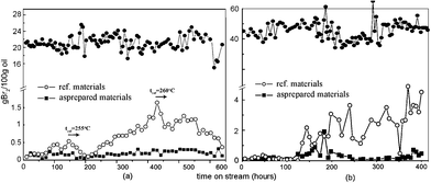 | ||
Fig. 1 Catalytic performance curves of ref.catalysts and as-prepared ultrastable nanocatalysts on (a) general feedstock with higher space velocity (T = 240 °C, VH2![[thin space (1/6-em)]](https://www.rsc.org/images/entities/char_2009.gif) : :![[thin space (1/6-em)]](https://www.rsc.org/images/entities/char_2009.gif) Voil = 600, SV = 4.0 h−1, P = 2.8 MP, ref.catalyst is LY9802) and (b) FR feedstock (T = 260 °C, VH2 Voil = 600, SV = 4.0 h−1, P = 2.8 MP, ref.catalyst is LY9802) and (b) FR feedstock (T = 260 °C, VH2![[thin space (1/6-em)]](https://www.rsc.org/images/entities/char_2009.gif) : :![[thin space (1/6-em)]](https://www.rsc.org/images/entities/char_2009.gif) Voil = 900, SV = 2.3 h−1, P = 2.2 MP, ref.catalyst is HR406). The changes in BN of the inlet feedstock by time are listed on the upper part of the graphs. Voil = 900, SV = 2.3 h−1, P = 2.2 MP, ref.catalyst is HR406). The changes in BN of the inlet feedstock by time are listed on the upper part of the graphs. | ||
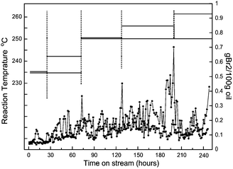 | ||
| Fig. 2 Accelerated catalytic performance curves with high amount of organic Si species (50 ppm) of ref.catalyst (LY9802(•)) and as-prepared ultrastable nanocatalysts (■). | ||
The photograph and high-resolution transmission electron microscopy (HRTEM) images of nanocatalysts are shown in Fig. 3 and the TEM images of ref.catalysts are shown in the supporting information (Fig. S2, ESI†). Fig. 3a and 3b show photographs of the morphology of NANO-DN and NANO-UP. As seen, considering percent of void (ε), the sphere-shaped NANO-UP offers high stack density, which would make the preliminary startup of the reaction facile, while the trilobal morphology of NANO-DN offers low stack density, which would make the latter reagents easily transfer to the end. Fig. 3c and 3d show the HRTEM images corresponding to Fig. 3a and 3b, respectively. It can be seen that the active components of Co-Mo-Ni based species are highly dispersed on the TiO2/Al2O3 nanosubstrates, as shown in Fig. 3c. With further magnification, some clusters as small as 1 nm could be seen. Fig. 3d shows the active Ni–Mo based species highly dispersed on the TiO2/Al2O3 nanosubstrates. Even with further and more careful observation, the biggest cluster did not reach 3 nm, which implies that the active components were well dispersed. Fig. 3e and 3f show the micro-area EDX analyses corresponding to Fig. 3c and 3d, which reveal that the surfaces of nano alumina are covered by Co, Mo and Ni sulfides on NANO-DN and Ni and Mo sulfides on NANO-UP. The high dispersibility was also investigated by X-ray diffraction (XRD) shown in Fig. 4 The as-prepared γ-Al2O3 could be indexed to JACDS 80-1385. The peaks of shielded TiO2 and active components of Co, Mo and Ni species could not be found on XRD curves, which implies there was no deep growth and aggregation. Furthermore, it was reported that one of the most important factors of hydrorefinery is rooted in low-indexed edge terminations of MoS224 and Mo5+. The absorption of XPS lining at 231 eV and 234 eV indexes the MoOx (Mo5+).25Fig. 5 shows the comparisons of XPS analysis for NANO-DN, NANO-UP, HR406 and LY9802. The as-prepared nanocatalysts with ultrafine TiO2 shield have superior active Mo5+. With the area integral, it could be calculated that the NANO-DN has over 1.93% active atomic Mo and the NANO-UP has over 1.54% active atomic Mo. However, the ref.catalysts have just less than 1.4% active atomic Mo. Thus, the as-prepared nanocatalysts offered better hydrorefining performance.
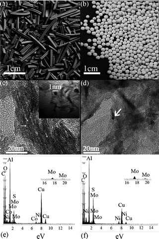 | ||
| Fig. 3 Photographs of molding catalysts, shot by a Nikon camera. (a) NANO-DN and (b) NANO-UP; HRTEM images of (c) NANO-DN and (d) NANO-UP. (indicated by white arrows). EDX analysis of (e) NANO-DN and (f) NANO-UP. | ||
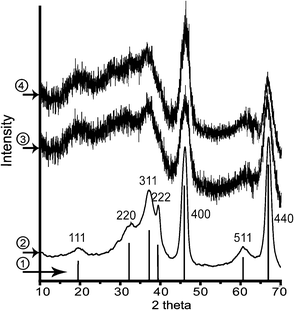 | ||
Fig. 4 Compared XRD curves of  standard γ-Al2O3 (JACDS 80-1385), standard γ-Al2O3 (JACDS 80-1385),  asprepared TiO2 shielded γ-Al2O3, asprepared TiO2 shielded γ-Al2O3,  NANO-DN and NANO-DN and  NANO-UP. NANO-UP. | ||
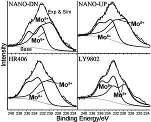 | ||
| Fig. 5 Distribution of Mo species from XPS analysis on as-prepared nanocatalysts of NANO-DN, NANO-UP, HR406 and LY9802. | ||
In summary, the ultrastable PGHr nanocatalysts were prepared with a facile and general impregnating method. Buffer impregnant and ultrafine TiO2 shielded nano-aluminum oxide techniques were combined to make the catalysts very stable at high SV for general feedstock of C6–C8 and more complex feedstock of full-ranged content. The catalysts showed good activity and stability, as well as good hydrorefining performance on resisting the rigorous effect of Si-deposition. The HRTEM images show that active components on the TiO2 shielded supports are less susceptible to sintering during high temperature calcinations and the surface is averagely covered by less than 1 nm nanoclusters. XPS shows that the as-prepared nanocatalysts have high amounts of active Mo5+, which correspond to their nature of high activity. Therefore, based on the facile preparation and ultrastability under the condition of high SV, complex feedstock and rigorous impurity, it is expected that these nanocatalysts could be easily extended to large-scale production and practical industrial application.
Experimental
Preparation of TiO2 shielded γ-Al2O3
Large surface-area γ-Al2O3 was prepared by following the below steps: Al2(SO4)3·18H2O and NaAlO2 were dissolved into water to make 1 M and 2.5 M solution, respectively. Under the conditions of pH = 8 and strong blending, both the solutions were then mixed slowly to form white precipitate. After aging the precipitate for around 2 h, it was washed by water several times to remove Na+ and SO42−. The precipitate was dried in an oven at 80 °C for 12 h and calcined under 550 °C for 6 h. TiO2shielded γ-Al2O3 was prepared by immerging as-prepared γ-Al2O3 (Brunauer–Emmett–Teller (BET) surface is 320 m2 g−1) into 0.01 M Ti(OC4H9)4 (TBT) hexane solution and hydrolyzing by vapors in atmosphere. The final TiO2 shielded γ-Al2O3 with mass ratio of TiO2![[thin space (1/6-em)]](https://www.rsc.org/images/entities/char_2009.gif) :
:![[thin space (1/6-em)]](https://www.rsc.org/images/entities/char_2009.gif) Al2O3 of 1.0
Al2O3 of 1.0![[thin space (1/6-em)]](https://www.rsc.org/images/entities/char_2009.gif) :
:![[thin space (1/6-em)]](https://www.rsc.org/images/entities/char_2009.gif) 100.0 was dried at 80 °C for 6 h and collected.
100.0 was dried at 80 °C for 6 h and collected.
Preparation of NANO-UP and NANO-DN nanocatalysts
To formulate buffer solution, dipotassium hydrogen phosphate (K2HPO4) and citric acid (C6H8O7·4H2O) were mixed to form a solution with a pH of 2. Then the solution was implanted into 0.1% ureaphosphate solution to make the final buffer solution. To formulate impregnants, nickel nitrate (Ni(NO3)2·6H2O) and ammonium hyptamolybdate ((NH4)6Mo7O24·4H2O) were implanted into buffer solution to form impregnant for NANO-UP. The impregnant of NANO-UP containing NiOx-MoOx active components has the mass ratio of P2O5![[thin space (1/6-em)]](https://www.rsc.org/images/entities/char_2009.gif) :
:![[thin space (1/6-em)]](https://www.rsc.org/images/entities/char_2009.gif) NiO
NiO![[thin space (1/6-em)]](https://www.rsc.org/images/entities/char_2009.gif) :
:![[thin space (1/6-em)]](https://www.rsc.org/images/entities/char_2009.gif) MoO2 of 12.5
MoO2 of 12.5![[thin space (1/6-em)]](https://www.rsc.org/images/entities/char_2009.gif) :
:![[thin space (1/6-em)]](https://www.rsc.org/images/entities/char_2009.gif) 5.0
5.0![[thin space (1/6-em)]](https://www.rsc.org/images/entities/char_2009.gif) :
:![[thin space (1/6-em)]](https://www.rsc.org/images/entities/char_2009.gif) 15.0. Similarly, nickel nitrate (Ni(NO3)2·6H2O), ammonium hyptamolybdate ((NH4)6Mo7O24·4H2O) and cobalt acetate (Co(CH3COO)2·4H2O) were implanted into buffer solution to form impregnant for NANO-DN. The impregnant of NANO-DN containing NiOx-MoOx-CoOx active components has the mass ratio of P2O5
15.0. Similarly, nickel nitrate (Ni(NO3)2·6H2O), ammonium hyptamolybdate ((NH4)6Mo7O24·4H2O) and cobalt acetate (Co(CH3COO)2·4H2O) were implanted into buffer solution to form impregnant for NANO-DN. The impregnant of NANO-DN containing NiOx-MoOx-CoOx active components has the mass ratio of P2O5![[thin space (1/6-em)]](https://www.rsc.org/images/entities/char_2009.gif) :
:![[thin space (1/6-em)]](https://www.rsc.org/images/entities/char_2009.gif) NiO
NiO![[thin space (1/6-em)]](https://www.rsc.org/images/entities/char_2009.gif) :
:![[thin space (1/6-em)]](https://www.rsc.org/images/entities/char_2009.gif) MoO2
MoO2![[thin space (1/6-em)]](https://www.rsc.org/images/entities/char_2009.gif) :
:![[thin space (1/6-em)]](https://www.rsc.org/images/entities/char_2009.gif) CoOx of 2.0
CoOx of 2.0![[thin space (1/6-em)]](https://www.rsc.org/images/entities/char_2009.gif) :
:![[thin space (1/6-em)]](https://www.rsc.org/images/entities/char_2009.gif) 1.0
1.0![[thin space (1/6-em)]](https://www.rsc.org/images/entities/char_2009.gif) :
:![[thin space (1/6-em)]](https://www.rsc.org/images/entities/char_2009.gif) 15.0
15.0![[thin space (1/6-em)]](https://www.rsc.org/images/entities/char_2009.gif) :
:![[thin space (1/6-em)]](https://www.rsc.org/images/entities/char_2009.gif) 3.0.
3.0.
The synthesis of ultrastable nanocatalysts: The as-prepared impregnants of NANO-UP and NANO-DN were implanted into the substrates of TiO2 shielded γ-Al2O3 with mass ratios of 0.6![[thin space (1/6-em)]](https://www.rsc.org/images/entities/char_2009.gif) :
:![[thin space (1/6-em)]](https://www.rsc.org/images/entities/char_2009.gif) 1.0 and 0.8
1.0 and 0.8![[thin space (1/6-em)]](https://www.rsc.org/images/entities/char_2009.gif) :
:![[thin space (1/6-em)]](https://www.rsc.org/images/entities/char_2009.gif) 1.0 respectively. The as-prepared materials were then calcined under 480 °C for 6 h to form the ultrastable nanocatalysts of NANO-UP and NANO-DN.
1.0 respectively. The as-prepared materials were then calcined under 480 °C for 6 h to form the ultrastable nanocatalysts of NANO-UP and NANO-DN.
Investigation of prepared NANO-UP and NANO-DN nanocatalysts
The TEM and HRTEM were performed on a FEI Tecnai 20 STWN. X-ray powder diffraction was carried out on a Bruker D8 X-ray diffractometer with Cu-Kα radiation (λ = 1.5418 Å; 40 kV, 200 mA). N2 adsorption was measured on a Micromeritics Tristar 3000 instrument. XPS analysis was carried out on a PHI 5000C ESCA System.Catalytic performances of prepared NANO-UP and NANO-DN nanocatalysts
The catalytic performances of nanocatalysts were investigated on continuous-reacted instruments with immobile beds produced by HUARONG Co. Ltd of China. Before reaction, 10% amount dimethyl disulfide of catalysts was injected into reactor to make vulcanized catalysts. Eqn (1) shows the factors concerning the consideration of reaction. Herein, Gf is the total amount of feedstock, Mf is average molecular weight of feedstock. It can be seen, that R, T, P, and πr2h are factors of conditions and instruments, the ε (percent of void, dominant by packing method) and V and m (pore volume and weight of catalysts) are factors of catalysts. Through altering the ε, V, m and temperature, the catalysis were optimized and stabilized for long term service. | (1) |
As shown in Fig. S1 (ESI†), the H2 and feedstock (oil) were injected into the reactor from the top and passed through the catalysts' beds. The NANO-UP and NANO-DN were packed to offer the advisable ε and sufficient activity. The optimized height of h1 to h2 is 1![[thin space (1/6-em)]](https://www.rsc.org/images/entities/char_2009.gif) :
:![[thin space (1/6-em)]](https://www.rsc.org/images/entities/char_2009.gif) 3.
3.
Acknowledgements
The authors thank the partially financial support from the SINOPEC, NSFC (21073237, 20903024), SSTDF 10QB1404700 and PSF 200902263 and thank the helpful discussion from Dr Yingchun Ye and Dr Xiaohong Li.References
- (a) J. E. Mark, Acc. Chem. Res., 2006, 39, 881 CrossRef CAS; (b) A. Meldrum, R. F. Haglund, L. A. Boatner and C. W. White, Adv. Mater., 2001, 13, 1431 CrossRef CAS.
- (a) J. Xu and J. Y. Ying, Angew. Chem., Int. Ed., 2006, 45, 6700 CrossRef; (b) M. Shokouhimehr, Y. Piao, J. Kim, Y. Jang and T. Hyeon, Angew. Chem., Int. Ed., 2007, 46, 7039 CrossRef CAS.
- (a) H. Zeng, J. Li, J. P. Liu, Z. L. Wang and S. Sun, Nature, 2002, 420, 395–398 CrossRef CAS; (b) M. H. Bartl, S. W. Boettcher, K. L. Frindell and G. D. Stucky, Acc. Chem. Res., 2005, 38, 263 CrossRef CAS.
- N. Sakamoto, S. Araki and M. Yoshimura, J. Am. Cera. Soc., 2008, 92, 157 CrossRef.
- (a) T. C. Merkel, B. D. Freeman, R. J. Spontak, Z. He, I. Pinnau, P. Meakin and A. J. Hill, Science, 2002, 296, 519 CrossRef CAS; (b) F. Croce, G. B. Appetecchi, L. Persi and B. Scrosati, Nature, 1998, 394, 456 CrossRef CAS.
- (a) Y. Wang, Acc. Chem. Res., 1991, 24, 133 CrossRef CAS; (b) N. Liu, Z. Chen, D. R. Dunphy, Y. Jiang, R. A. Assink and C. J. Brinker, Angew. Chem., Int. Ed., 2003, 42, 1731 CrossRef CAS.
- S. Choi, J. Coronas, E. Jordan, W. Oh, S. Nair, F. Onorato, D. F. Shantz and M. Tsapatsis, Angew. Chem., Int. Ed., 2008, 47, 552 CrossRef CAS.
- I. Moriguchi, Y. Shono, H. Yamada and T. Kudo, J. Phys. Chem. B, 2008, 112, 14560 CrossRef CAS.
- D. G. Shchukin, G. B. Sukhorukov and H. Möhwald, Angew. Chem., Int. Ed., 2003, 42, 4472 CrossRef CAS.
- (a) Y. S. Pek, A. C. A. Wan, A. Shekaran, L. Zhuo and J. Y. Ying, Nat. Nanotechnol., 2008, 3, 671 CrossRef CAS; (b) K. Haraguchi and H. Li, Angew. Chem., Int. Ed., 2005, 14, 6500 CrossRef.
- Y. Wang and N. Herron, J. Phys. Chem., 1991, 95, 525 CrossRef CAS.
- B. Patrick and K. V. Prashant, J. Am. Chem. Soc., 2008, 130, 8890 CrossRef.
- Y. Qiao, S. Bao, C. Li, X. Cui, Z. Lu and J. Guo, ACS Nano, 2008, 2, 113 CrossRef CAS.
- P. Krawiec, C. Weidenthaler and S. Kaskel, Chem. Mater., 2004, 16, 2869 CrossRef CAS.
- H. Tsuji and Y. Koyasu, J. Am. Chem. Soc., 2002, 124, 5608 CrossRef CAS.
- P. Jin, Q. Chen, L. Hao, R. Tian, L. Zhang and L. Wang, J. Phys. Chem. B, 2004, 108, 6311 CrossRef CAS.
- D. J. Griffiths, D. M. Luntz and J. L. James, Oil Gas J., 1968, 27, 613 Search PubMed.
- J. F. Lepage, P. Courty, E. Freund, J. P. Franck, Y. Jacquin, B. Juguin, C. Marcilly, G. Marino, J. Miguel and H. V. Landeghem, Applied Heterogeneous CatalysisGulf Publishing Co.: Houston, TX, 1987; p 329 Search PubMed.
- T. B. Lin and T. C. Chou, Appl. Catal., A, 1994, 108, 7 CrossRef CAS.
- (a) H. Pines, J. Am. Chem. Soc., 1958, 80, 3801 CrossRef; (b) A. V. Paul, E. Arkady and J. A. Robert, J. Am. Chem. Soc., 2003, 125, 2064 CrossRef; (c) F. Y. Cheng, J. Chen and X. L. Gou, Adv. Mater., 2006, 18, 2561 CrossRef CAS.
- (a) F. P. McCandless and L. Berg, Ind. Eng. Chem. Process Des. Dev., 1970, 9, 110 CrossRef CAS; (b) G. Zhu, J. M. Tanski, D. G. Churchill, K. E. Janak and G. Parkin, J. Am. Chem. Soc., 2002, 124, 13658 CrossRef CAS.
- R. Prins, Angew. Chem. Int. Ed., 2001, 40, 1551 CrossRef CAS and references therein.
- (a) K. P. de Jong, Synthesis of Solid Catalysts, 2009, 301 Search PubMed; (b) J. Kibsgaard, J. V. Lauritsen, E. Lægsgaard, B. S. Clausen, H. Topsøe and F. Besenbacher, J. Am. Chem. Soc., 2006, 128, 13950 CrossRef CAS; (c) C. H. Lai, M. Y. Lu and L. J. Chen, J. Mater. Chem., 2012, 22, 19 RSC.
- (a) J. V. Lauritsen, R. T. Vang and F. Besenbacher, Catal. Today, 2006, 111, 34 CrossRef CAS; (b) Y. Okamoto, Catal. Today, 2008, 132, 9 CrossRef CAS.
- C. Thomazeau, C. Geantet, M. Lacroix, M. Danot, V. Harlé and P. Raybaud, Appl. Catal., A, 2007, 322, 92 CrossRef CAS.
Footnotes |
| † Electronic Supplementary Information (ESI) available: schematic diagram of the process for PGHr and TEM of ref-catalyst. See DOI: 10.1039/c2ra20953e |
| ‡ Mr. J. Zhu and Mrs. Y. Cheng offered equal contributions. |
| This journal is © The Royal Society of Chemistry 2012 |
