Residence time distribution, a simple tool to understand the behaviour of polymeric mini-flow reactors
Victor
Sans
*ab,
Naima
Karbass
a,
M. Isabel
Burguete
a,
Eduardo
García-Verdugo
*a and
Santiago V.
Luis
a
aDepartment of Inorganic and Organic Chemistry, University Jaume I/CSIC, Avda. Sos Baynat s/n, E-12071, Castellón, Spain. E-mail: eduardo.garcia-verdugo@qio.uji.es
bSchool of Chemistry, University of Glasgow, G12 8QQ, Glasgow, UK. E-mail: victors@chem.gla.ac.uk
First published on 16th July 2012
Abstract
A simple method for the determination of the residence time distribution (RTD) of different polymer-based mini-flow reactors has been developed. The flow patterns have been adjusted employing the axial dispersion model, allowing a quantitative comparison of the flow patterns of the different structures. The use of different pulse tracer experiments highlights the differences in reactor behaviour depending on the nature (gel vs. macroporous) and shape (beads vs. monoliths) of the polymeric materials used in the reactor preparation. Thus, reactors based on monolithic columns showed a superior performance in terms of flow distribution when compared to commercial bead-shaped packed polymers of different sizes and backbone structure, confirming previous experimental results. These differences can help to understand the different catalytic efficiency detected for these mini-flow fixed-bed reactors. The model presented can help to properly design new processes based on the use of continuous flow reactors facilitated by functional materials, which is becoming an essential goal nowadays, in particular in the context of developing new efficient and clean technologies.
Introduction
The synthesis of organic molecules by the application of so-called flow chemistry has gained a great deal of attention in recent years, due to its inherent higher efficiency compared to traditional batch processes.1 Although some nice examples of flow organic synthesis have been reported in the homogeneous phase,2 the synergetic combination of continuous-flow and heterogeneous reagents, catalysis and scavengers represents a very efficient strategy for both the development of simple organic synthetic transformations and the preparation of small complex molecules of pharmaceutical relevance.3–5 Furthermore, the combination of these tools with other facilitating techniques (the use of neoteric solvents, microwave, sonochemistry, etc.) has led to the development of new green and more efficient synthetic processes.6The potential of solid-supported reagents, scavengers and catalysts for developing flow processes has been realized as one of their key properties.1,3,7 The matrices used as the supports can be classified, according to their nature, into organic and inorganic. Most of the work carried out has concentrated on the use of two relatively simple polymeric networks: cross-linked polystyrene and polyacrylic derivatives. Alternatively, functionalised inorganic materials obtained either by modification of different oxides or by sol–gel processes have also been successfully used.8 In this way, the joint efforts of synthetic and materials chemists and chemical engineers have resulted in the development of continuous flow devices and microreactors, which allow the rapid preparation of compounds with minimum workup9 and facilitate both automation and fast operational optimisation.10
Different reactor configurations have been assayed to design flow processes attending to the type and shape of the material employed. Among them, some non exhaustive examples can be mentioned: micrometre-sized open tubes with catalytic moieties grafted on the walls,11 packed-bed reactors,1,7 and monolithic reactors.12–14 The selection of the reactor configuration can lead, in some cases, to significant differences in performance. Thus, for instance, a recent report by Coq and coworkers addressed the use of hierarchical silica monoliths grafted with acidic and basic moieties as continuous flow reactors for catalysis. Processes based on the monolithic reactors proved to be 2 to 10 folds more productive than packed-bed or batch-mode reactors in two different model reactions: Knoevenagel condensation and transesterification.15 McQuade and coworkers pointed out the importance of the nature of the support to develop a pressure-driven system by passing different solvents through a packed-bed reactor and qualitatively assessing whether the flow was free or constricted.16 Typically, gel-type lightly crosslinked resins only swell in certain solvents, which allows a proper flow through the microchannels of the resin (usually beads) exclusively in the presence of the proper swelling solvent. Nevertheless, the swelling is accompanied by a change in volume that can be very important, thus affecting the packing. Highly cross-linked or macroreticular resins and silicas, on the other hand, allow optimal flow conditions, close to plug-flow, under nearly all solvent conditions as they do not appreciably swell, thus not producing changes in the packing. There are also significant differences between the fixed-bed reactors, packed either with beads or monolithic polymeric materials, when they are used for both synthesis and separation processes. Thus, employing a simple method for understanding and controlling the variables governing the flow distribution is of the greatest interest.17 Here, different mini-flow packed-bed reactors, which were prepared using different types of cross-linked polymers (gel-type, macroporous beads and macroporous monoliths), have been characterized by means of residence time distribution (RTD) studies using simple pulse tracer experiments. The flow patterns allow the understanding of the different catalytic efficiencies observed for the mini-flow reactors used in C–C coupling reactions.
Experimental
Monolithic mini-flow reactors 1 and 2 (Mfr-1 and Mfr2)
Monolithic reactors based on PS–DVB (polystyrene-divinylbenzene) polymers were prepared by the polymerisation of different polymer mixtures, using a previously reported methodology.18 The compositions selected (Table 1) allowed us to obtain monoliths with different ranges of porosity and pore size (see Table 1).
| Mini-flow reactor | ClVB (%)a | DVB (%)a | ρ ap (g cm−3)c | d50 (μm)d | pore volume (cm3 g−1) | ε o e |
|---|---|---|---|---|---|---|
a Expressed as % weight of the polymerisation mixture.
b Toluene:dodecanol 1![[thin space (1/6-em)]](https://www.rsc.org/images/entities/char_2009.gif) :4 was used as the porogenic mixture. Co-polymerization was initiated by AIBN and carried out at 70 °C using a 2:3 weight ratio monomeric mixture–porogen, inside AISI 316 tubing of 15 cm length and 1/4 din.
c Apparent density: massmaterial/densitymaterial.
d Diameter at 50% of pore size distribution.
e Open porosity: void volume/total volume. :4 was used as the porogenic mixture. Co-polymerization was initiated by AIBN and carried out at 70 °C using a 2:3 weight ratio monomeric mixture–porogen, inside AISI 316 tubing of 15 cm length and 1/4 din.
c Apparent density: massmaterial/densitymaterial.
d Diameter at 50% of pore size distribution.
e Open porosity: void volume/total volume.
|
||||||
| Mfr-1b | 16 | 24 | 0.367 | 0.39 | 1.8694 | 0.69 |
| Mfr-2b | 12 | 18 | 0.378 | 4.69 | 1.6383 | 0.62 |
Mini-flow reactor 3 (Mfr-3)
This reactor was prepared by packing a commercial macroporous Merrifield resin obtained in the form of beads. A chloride loading of 1.2 mmol Cl g−1 and a DVB content of ca. 55% DVB was obtained by means of Raman spectroscopy.19 The bead size was estimated to be 70.4 μm with a standard deviation of 12.7 μm. This material was packed in a 15 cm stainless steel column with a 1/4 inch internal diameter similar to the one used for the preparation of Mfr-1 and Mfr-2. The void volume was determined by filling the empty space with a known solvent (THF). In this way, the porosity was found to be 0.74.Mini-flow reactor 4 (Mfr-4)
This reactor was prepared by packing an Amberlite resin IR-200 in the Na+ form in a 15 cm stainless steel column with a 1/4 inch internal diameter as before. The average bead size was 534.85 μm with a standard deviation of 127.21 μm.Mini-flow reactor 5 (Mfr-5)
This reactor was prepared by packing a commercial gel-type Merrifield resin (4.3 mmol g−1, 1% crosslinked) in a glass column (10 × 100 mm, with an adjustable volume from 1–10 mL). Thus, half of the column (5 mL) was filled with the polymer. When the resin was wetted with the different solvents (toluene or acetonitrile (ACN)), the volume of the reactor was adjusted to the volume occupied by the swollen resin.PdNPs–SILLP (PalladiumNanoParticles–Supported-Ionic-Liquid-Like-Phases) reactors
Mini-flow reactors PdNPs–SILLP-1 and PdNPs–SILLP-2 were prepared by modification of the mini-flow reactors Mfr-1 and Mfr2 and tested in the Heck reaction in hot pressurised ethanol as previously reported.20 In a similar way, the PdNPs–SILLP-3 mini-flow reactor was also prepared by the modification of the corresponding Mfr-3 reactor.Pulse tracer experiments
All the experiments were carried out using the set-up shown schematically in Fig. 1, using a Hitachi HPLC pump, a fixed wave length UV-visible detector and a Rheodyne injection valve with a 50 μl loop. All the connections were made with 1/16 HPLC tubing to try to minimize the dead volume. The tracer used was toluene, although for the experiments performed in toluene as the solvent, nitrobenzene was used as tracer. The reactors were prepared using either a 10 mL Omnifit glass (10 × 100 mm) or stainless steel columns (5 cm length and 0.4 cm diameter). Flow rates ranging from 0.1 to 3 mL min−1 were investigated with the use of acetonitrile as the solvent in most cases. Monolithic columns were limited to a maximum flow of 2.5 mL min−1 to avoid overpressures, which could damage the columns. The variation of the tracer with time was determined by UV-vis detection at 224 nm for toluene and at 240 nm when nitrobenzene was used as the tracer. | ||
| Fig. 1 The schematic experimental set-up for the RTD studies. | ||
C–C coupling reaction under flow conditions
The reaction of iodobenzene with methyl acrylate was examined in a continuous flow system using hot pressurized ethanol as the solvent. A solution of iodobenzene and methyl acrylate (0.67 mol L−1 in EtOH, 1:1.1:2 molar ratio iodobenzene:methyl acrylate:Et3N) was pumped at a flow rate of 0.2 mL min−1 through the monolithic reactor. Aliquots were taken at regular time intervals and analyzed by HPLC for the methylcinnamate content.
Results and discussion
In this work, packed-bed reactors, functionalized with either polymeric beads or monoliths were used, as this is the easiest approach towards the design of polymer assisted flow devices. Three classical reactor designs, using this approach, have been described in detail by Hodge.1,7b In this regard, the more common configuration is based on the flow-trough packed-bed reactors flowing either upwards or downwards using a pressure-driven flow. Alternatively, the use of electrosmotic-driven flows also allows continuous processes using a wider range of packing materials.21 However, these systems are far more complex than pressure-driven systems, being restricted to polar solvents.Chloromethylated resins were selected as the starting polymeric materials as chloromethyl groups allow the easy introduction of a great number of reagents, scavengers and catalysts.22 A wide range of flow processes have been developed with fixed-bed reactors based on those materials. In principle, the flow patterns of the fixed-bed reactors should not be significantly modified by the introduction of such groups and the tools here reported will also be applicable for mini-flow reactors packed with modified resins. An example of those modified polymers should be the use of supported ionic liquid like phases (SILLPs) prepared from chloromethylated PS–DVB polymers for the immobilisation of different types of catalysts.23 Thus, for instance, metal nanoparticles (MNPs) can be synthesised and stabilised by different SILLPs.20,24 Those MNPs–SILLP composites can be used as the packing material to prepare fixed-bed reactors. Indeed, SILLP mini-flow reactors bearing PdNPs are able to efficiently catalyse C–C coupling reactions between iodobenzene and methyl acrylate using hot pressurized ethanol as the solvent (200 °C and 80 bars).20 However, as it is shown in Table 2, the catalytic efficiency obtained for the different PdNP–SILLP mini-flow reactors based on either monolithic or bead materials (entries 1 and 2 vs. 3) was significantly different (up to one order of magnitude). Moreover small differences were found for the mini-flow reactors based on PdNPs–SILLPs supported on monolithic polymers prepared with slightly different compositions.25 RTD studies may help us to rationalise such differences based on the nature of the material employed to pack the corresponding fixed-bed mini-flow reactors.
| Entry | Fixed-bed material | Pd loadinge | Yield (%)f | Productivityg |
|---|---|---|---|---|
|
a Reaction conditions: 200 °C and 80 bars; 0.2 mL min−1; PhI concentration 0.67 mmol L−1; 1:1.1: 2 PhI:methylacrylate:Et3N ratio; reactor size: 15 cm length × ¼ inch internal diameter.
b Prepared from Mfr-1.
c Prepared from Mfr-2.
d Prepared from Mfr-3.
e mmol Pd g−1 polymer calculated by ICP-MS.
f Calculated by HPLC analysis of samples collected at the reactor outlet.
g (mol Product)·x (mol cat)−1·x min−1.
|
||||
| 1 | Monolithb | 0.21 | 93 | 22.2 |
| 2 | Monolithc | 0.18 | 50 | 19.7 |
| 3 | Beadsd | 0.63 | 70 | 3.9 |
Residence time distribution (RTD) studies
The knowledge about the flow patterns inside a reactor is vital to predict and explain the general behaviour of the reactor and the above mentioned differences. Among the different possibilities and from an engineering point of view, the residence time distribution (RTD) of a reactor is one of the most informative characterizations of the flow pattern in a chemical reactor.26 For this reason, there have been numerous efforts to study the residence time distribution inside vessels.27 The theory of RTD was first proposed by MacMullin and Weber,28 and worked out in more detail by Danckwerts some years later.29 It provides information on how long the various elements have been in the reactor.30 It is a quantitative measure of the degree of back mixing within a system31 and allows for an accurate kinetic modelling of the system helping to achieve or preserve a desired flow pattern during reactor design. Besides, RTD allows for a more thorough comparison between systems having different configurations of the reactor, it is an extraordinarily simple tool for a successful process scale-up. In general, the RTD of mini-flow reactors can be determined by simple tracer experiments. In these experiments, an inert tracer32 is injected into the solvent stream flowing through the reactor vessel and its distribution is analyzed, for instance by UV-vis, at the outlet, monitoring the concentration of the tracer over time (see Fig. 1).29,33 In this way, from the experimental curves obtained it is possible to calculate the E(t) curve, the mean residence time (τ) and the variance by applying eqn (1)–(3): | (1) |
 | (2) |
 | (3) |
In order to facilitate the comparison of the results obtained for the different mini-flow reactor configurations (involving, for instance, different packings), it is convenient to employ dimensionless units:
 | (4) |
The mean liquid velocity has been calculated according to eqn (5).33
 | (5) |
Where L is the length of the mini-flow reactor.
E(t) curves as a qualitative tool to study the characteristics of gel-type and macroporous polymer-packed reactors.
The nature, shape and morphology of the polymers are key parameters to obtain a proper reactor design. In general, gel-type resins are by far the most employed supports to develop polymer supported systems, especially when batch processes are considered.22 By definition, gel-type resins do not possess any permanent porosity and thus their swelling in an appropriate solvent is required for any reaction to occur in the interior of the beads.34 The selection of the solvent depends on the chemical nature of the polymeric backbone and that of the functional groups being introduced. Thus, for PS–DVB matrices solvents like toluene or dichloromethane are very appropriate, while more polar solvents are compatible with acrylic-derived resins. In this regard, to design mini-flow reactors based on gel-type polymers, it is essential that the packing will estimate the change in volume that will take place by the swelling/shrinking of the polymer with the solvent employed for the process. The need for a proper adjustment of the reactor design has hampered the use of gel-type resins for efficient flow processes many times. However, if this increment in volume upon swelling is considered, gel-type resins can be used without problem.35 An alternative is the use of macroporous resins instead of microporous gel-type polymers in order to prevent column blockage due to polymer swelling, as they do not swell with solvents.16 The third approach we have considered is the use of mini-flow reactors based on monolithic materials. Monoliths are macroporous materials with a well defined structure of continuous channels and confined spaces allowing a simple development of flow-through reactor systems. They present high mechanical and chemical stability and their morphological properties can be finely tuned by adjusting the composition of the polymerization mixture and reaction conditions. Functional groups can be attached to the polymeric matrix either by grafting or by co-polymerization,36 enabling very interesting applications as supports for catalysts in continuous-flow processes.The use of monolithic materials for reactor design has shown a series of advantages compared with the use of bead gel-type polymers, which have been highlighted by different authors.12–14 However, a clear experimental study has not been performed, so far, to explain such differences.
Fig. 2 (a and b) illustrates the large differences in reactor volume, for a column packed with the same amount of a gel-type resin, in the presence of either a good swelling solvent (toluene) or a non-swelling solvent (acetonitrile, ACN). In this case, an adjustable device can be used to adjust the volume of the reactor to that of the resin to prepare a reproducible flow through the system. As shown in Fig. 2 the volume of macroporous resins, in particular in the form of monoliths, is not affected by the solvent. This figure also shows the profiles of the E(t) curves, obtained for the toluene as the tracer, revealing the significant differences in the corresponding flow patterns. When the gel-type resin was not swollen, a very broad E(t) curve was obtained for a flow rate of 1 mL min−1. Under the same conditions, the microporous resin swollen in toluene showed a more defined pattern with a bimodal distribution, which may indicate the presence of preferential channels, in good agreement with the clear differences observed when the same packed gel-type reagent, scavenger or catalyst is used with different solvents.1 On the contrary, as monolith polymers have a rigid structure, the same E(t) curve is to be expected independent of the solvent employed, as was experimentally seen (Fig. 2, right). For the monolithic system, the flow pattern found was significantly narrower than that obtained by reactors packed with gel-type resins, implying a much more uniform and less dispersed flow through the reaction vessel, thus being closer to an ideal plug flow reactor. Hence, monolithic columns are expected to offer better mixing and consequently offer superior yields and selectivities in heterogeneous catalytic reaction systems, where the contact between the substrates and the catalysts immobilized on the surface of the support is critical. It is interesting to note that polymeric monoliths have been used not only as supports for functional moieties but also as passive micromixers to enhance mixing efficiency.37 This indicates that mini-flow reactors based on monolithic materials offer clear advantages over those based on gel-type resins.
 | ||
| Fig. 2 Comparison of the flow patterns for mini-flow reactors packed with different polymers at a flow rate of 0.5 mL min−1. (a) Microporous resin. (b) Monolithic column. | ||
The qualitative analysis of the E(t) curves can also be used as a quality control to detect and understand the reactor defects or anomalies. For instance, at low flow rates the mini-flow monolithic reactor (Mfr-1) showed a long tail of tracer (Fig. 3, left). This was indicative of the presence of some degree of back mixing inside the reactor. In the case of the mini-flow reactor Mfr-2, the E(t) suggested a possible channelling problem at low flow rates (Fig. 3, right). This is probably due to the effect of small channels between the polymer and the column wall that served as preferential pathways for the fluid.
 | ||
| Fig. 3 Flow disturbances observed at low flow rates in monolithic columns. Left: The back mixing effect observed in the E(t) curve corresponding to Mfr-1 at 0.5 mL min−1. Right: The channelling effect observed in the E(t) curve corresponding to Mfr-2 at 0.25 mL min−1. | ||
Noteably, the flow problems detected in both monolithic columns were dependent not only on the inherent morphology of the materials, but also on the flow conditions. In both columns, an increase in the flow rate led to an increase of the symmetry of the RTD curves, revealing the disappearance or minimization of such disturbances (Fig. 4). This confirms the importance of performing pulse tracer experiments as routine tests when working with mini-flow reactors, since depending on the flow conditions, misbehaving flow patterns might occur that could affect their performance for the desired process. Moreover, these experiments can be a useful control check during the lifetime of the reactor to ensure that no blockade or channelling problems are generated during long term use.
 | ||
| Fig. 4 E(θ) curves corresponding to Mfr-1 (left) and to Mfr-2 (right) using different flows of ACN as the solvent and toluene as the tracer. | ||
In order to compare the results, the E(θ) curves corresponding to different column packings at the same flow rate (1 mL min−1 of ACN) have been represented in Fig. 5. They demonstrate how the continuous porous structure of these monoliths is a very suitable flow media, reflected in the narrow and high E(θ) curves, where the flow presents little axial dispersion and thus is closer to plug flow than in the case of bead-type resin packings. As expected, the packed reactor from smaller spheres (Mfr-3) shows less dispersive flow than the non-ideal packing obtained from larger beads (Mfr-4). Finally, the reactor from a microporous Merrifield shows a very big dispersion of the tracer, indicating that this type of polymer is much less appropriate for flow applications
 | ||
| Fig. 5 Comparison of E(θ) curves for the different polymeric packed columns obtained at a flow rate of 1 mL min−1 of ACN, using toluene as the tracer. | ||
From the experimental E(t) curves, the mean residence time (τ) and σ2 values were calculated. The results obtained are represented in Table 3.
| Entry | Mini-flow reactor | F (mL min−1) | τ (min) | σ 2 |
|---|---|---|---|---|
| 1 | Mfr-1 | 0.1 | 7.78 | 0.81 |
| 2 | 0.5 | 1.52 | 0.04 | |
| 3 | 0.75 | 1.01 | 0.02 | |
| 4 | 1 | 0.77 | 0.02 | |
| 5 | 1.5 | 0.52 | 0.01 | |
| 6 | Mfr-2 | 0.25 | 4.11 | 0.22 |
| 7 | 0.5 | 2.06 | 0.07 | |
| 8 | 0.75 | 1.38 | 0.04 | |
| 9 | 1 | 1.04 | 0.02 | |
| 10 | 1.5 | 0.69 | 0.02 | |
| 11 | Mfr-3 | 0.25 | 3.53 | 0.53 |
| 12 | 1 | 0.89 | 0.03 | |
| 13 | 1.5 | 0.60 | 0.02 | |
| 14 | 2 | 0.46 | 0.02 | |
| 15 | Mfr-4 | 0.5 | 1.48 | 0.53 |
| 16 | 1 | 0.73 | 0.15 | |
| 17 | 1.5 | 0.48 | 0.07 | |
| 18 | 2 | 0.35 | 0.04 |
In all cases, τ and σ2 decreased with the flow rate. The values of τ for the different columns were very similar, indicating comparable reactor volumes. However, important differences were observed depending on the packing. The mini-flow reactor based on the monolith with the lowest amount of porogenic mixture (Mfr-1) showed a lower σ2 in all the studied cases. This means that the flow of the tracer through this packing was the most homogeneous of all the studied cases, being the closest to an ideal plug flow reactor. Since this packing had the lowest porosity, the flow was also the most compact. On the other hand, a monolith packing having a higher amount of porogenic mixture lead to mini-flow reactors (Mfr-2) showing slightly higher values of dispersion (higher values of σ). Hence, the higher porosity produced a higher dispersion of the fluid. The packed reactors with a Merrifield macroporous resin (Mfr-3) or with an Amberlite polymer (Mfr-4) showed higher values of σ due to the problems associated with the packing of the beads.
Fitting the results to the dispersion model
In any packed-bed reactor, a careful control is required to avoid the formation of cracking or the floating of the beads as it may lead to an inhibition of the flow and the contact of the substrates and reagents with the active sites at the internal surfaces of the resin. In this regard, the model selected to characterize the RTD of the different packings was the axial dispersion. In this model, the axial motion of a fluid is due to the bulk motion and to a diffusive component characterized by a dispersion coefficient.38 Mathematically, this concept is described by the following: | (6) |
The parameter Dax characterizes the degree of back mixing during the flow inside the reactor. The dimensionless group is usually represented by the Péclet module.
 | (7) |
Under “open” boundary conditions, i.e. the flow is undisturbed at the inlet and outlet of the vessel, eqn (6) has an analytical solution:
 | (8) |
The experimental results were adjusted to eqn (8) by numerical integration, calculating the value of Pe that minimized the average value of the sum of the squares:
 | (9) |
 | ||
| Fig. 6 Fitting of the experimental results to the axial dispersion model for Mfr-1. Solid lines: experimental results; dotted lines: calculated results. (a) F = 1 mL min−1. (b) F = 0.75 mL min−1. (c) F = 0.5 mL min−1. (d) F = 0.1 mL min−1. | ||
The Péclet values were higher for monolithic polymers than for sphere packed columns (Fig. 7), indicating lower values of Dax and thus a flow profile closer to a plug flow reactor.
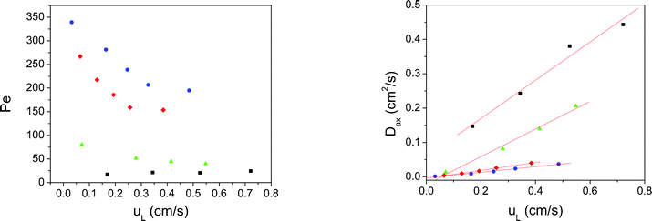 | ||
| Fig. 7 Analysis of the results for the different polymeric packings employing the dispersion model. Left: Péclet values obtained as a function of the linear velocity inside the reactors. Right: Axial dispersion coefficients calculated for each packing studied. Blue dots: Mrf-1; y = 0.081·x; R2 = 0.988. Red diamonds: Mrf-2; y = 0.116·x; R2 = 0.996. Green triangles: Mrf-3; y = 0.402·x; R2 = 0.989. Black squares: Mrf-4; y = 0.557·x; R2 = 0.977. | ||
A linear relationship was found between Dax and uL, which proved that the model is consistent in the range of flow rates studied. Mrf-1 and Mrf-2 showed the lowest values of Dax. Thus, monolithic columns are in all cases better systems for flow than sphere packed beds.
Monolithic polymers showed in all cases flow patterns closer to an ideal plug flow than the bead-shaped packings. In the bead-packing, a higher degree of back mixing was observed, resulting in higher dispersion coefficients. An increase in the diameter of the particles lead to a worse packing, which in turn was characterized by a higher degree of mixed flow.
The different flow pattern of the substrates through each mini-flow reactor studied has an important effect in continuous-flow catalytic reactions, especially on those cases where fast reaction kinetics might result in mass-transfer limited systems. This might be the case for the Heck reaction between iodobenzene and methyl acrylate at high temperatures in near critical ethanol. Indeed, Table 4 shows that mini-flow reactors with lower values of Dax present higher values of productivity. This is due to a better flow distribution within the reactor, which results in lower mass-transfer coefficients and better contact between the substrates and the catalyst, which is on the inner surface of the polymeric material. Other aspects that can influence the productivity of each catalytic system are the morphology of the Pd and the specific surface of the support. No significant differences were found by SEM in the morphology of the Pd. This was expected since the methodologies for deposition and reduction were very similar. The specific surface of the support was calculated for each reactor and even though a trend was found, where higher values of productivity corresponded to higher values of productivity, no direct correlation was observed. Hence, even though the effect of the specific surface can not be ruled out, the differences in productivity can be ascribed to the flow patterns of each catalyst packing.
Conclusions
In this article, we have demonstrated that RTD tracer experiments are very useful tools to characterize the flow patterns within polymeric packed columns and as quality control tools to detect defects or malfunctions in the columns. The different mini-flow reactors have been modelled employing the axial dispersion model. Monolith-based mini-flow reactors have proven to be superior to bead-based packed reactors in terms of flow distribution through the columns. This situation is reflected in lower values of the corresponding axial dispersion coefficients. The different flow patterns observed in the mini-flow reactors have proven to be reflected in the productivity of Heck reactions catalyzed by PdNPs supported on different kinds of polymeric systems, where lower values of the axial dispersion coefficients correspond to higher values of productivity. Thus, these tools can be used to easily understand the different catalytic efficiencies found when comparing different mini-flow reactors based on either monolithic or bead-type polymers functionalised with catalytic sites.Symbols
| E(t) | Residence time distribution curve (s) |
| C(t) | Tracer concentration |
| τ | Mean residence time (s) |
| σ | Variance |
| θ | Dimensionless time |
| uL | Mean liquid velocity (cm s−1) |
| Pe | Péclet module |
| Dax | Dispersion coefficient (cm2 s−1) |
Acknowledgements
Work supported by CICYT (CTQ2008-04412/CTQ2011-28903), Bancaja-UJI (P1-1B2009-58), and GV (ACOMP/2010/280).References
- S. V. Luis and E. García-Verdugo, Chemical Reactions and Processes under Flow Conditions, Royal Society of Chemistry, Cambridge, 2009 Search PubMed.
- (a) K. Geyer, T. Gustafsson and P. H. Seeberger, Synlett, 2009, 15, 2382 Search PubMed; (b) H. Kim, A. Nagaki and J. I. Yoshida, Nat. Commun., 2011, 2, 264 CrossRef; (c) T. Razzaq and C. O. Kappe, Chem. Asian. J., 2011, 5, 1274 Search PubMed.
- C. G. Frost and L. Mutton, Green Chem., 2010, 12, 1687 RSC.
- (a) I. Baxendale, S. Schou, J. Sedelmeier and S. Ley, Chem.–Eur. J., 2010, 16, 89 CrossRef CAS; (b) D. Webb and T. F. Jamison, Chem. Sci., 2010, 1, 675 RSC; (c) F. Venturoni, N. Nikbin, S. V. Ley and I. R. Baxendale, Org. Biomol. Chem., 2010, 8, 1798 RSC.
- (a) N. G. Anderson, Org. Process Res. Dev., 2001, 5, 613 CrossRef CAS; (b) P. Watts and S. J. Haswell, Drug Discovery Today, 2003, 8, 586 CrossRef CAS; (c) V. Bavykin, A. A. Lapkin, S. T. Kolaczkowski and P. K. Plucinski, Appl. Catal., A, 2005, 288, 175 CrossRef; (d) T. Glasnov, S. Findenig and C. Kappe, Chem.–Eur. J., 2009, 15, 1001 CrossRef CAS; (e) B. Ngamsom, A. M. Hickey, G. M. Greenway, J. A. Littlechild, T. McCreedy, P. Watts and C. Wiles, Org. Biomol. Chem., 2010, 8, 2419 RSC.
- (a) M. H. C. L. Dressen, B. H. P. van de Kruijs, J. Meuldijk, J. A. J. M. Vekemans and L. A. Hulshof, Org. Process Res. Dev., 2010, 14, 351 CrossRef CAS; (b) U. Hintermair, G. Francio and W. Leitner, Chem. Commun., 2011, 47, 3691 CAS.
- (a) A. Kirschning and G. Jas, Top. Curr. Chem., 2004, 242, 209 CrossRef CAS; (b) P. Hodge, Ind. Eng. Chem. Res., 2005, 44, 8542 CrossRef CAS.
- For a biocatalytic microreactor based on a mesoporous silica support, see: S. Kataoka, Y. Takeuchi, A. Harada, M. Yamada and A. Endo, Green Chem., 2010, 12, 331 RSC.
- (a) K. Geyer, J. D. C. Codée and P. H. Seeberger, Chem.–Eur. J., 2006, 12, 8434 CrossRef CAS; (b) G. Jas and A. Kirschning, Chem.–Eur. J., 2003, 9, 5708 CrossRef CAS.
- (a) J. P. McMullen, M. T. Stone, S. L. Buchwald and K. F. Jensen, Angew. Chem., Int. Ed., 2010, 49, 7076 CrossRef CAS; (b) M. Rasheed and T. Wirth, Angew. Chem., Int. Ed., 2011, 50, 357 CrossRef CAS; (c) A. J. Parrott, R. A. Bourne, G. R. Akien, D. J. Irvine and M. Poliakoff, Angew. Chem., Int. Ed., 2011, 50, 3788 CrossRef CAS.
- (a) N. Wang, T. Matsumoto, M. Ueno, H. Miyamura and S. Kobayashi, Angew. Chem., Int. Ed., 2009, 48, 4744 CrossRef CAS; (b) F. Costantini, E. M. Benetti, R. M. Tiggelaar, H. J. G. E. Gardeniers, D. N. Reinhoudt, J. Huskens, G. J. Vancso and W. Verboom, Chem.–Eur. J., 2010, 16, 12406 CrossRef CAS; (c) J. F Ng, Y. Nie, G. K. Chuah and S. Jaenicke, J. Catal., 2010, 269, 302 CrossRef CAS.
- For examples of mini-flow reactors based on inorganic monolithic materials: (a) A. Sachse, A. Galarneau, B. Coq and F. Fajula, New J. Chem., 2011, 35, 259 RSC; (b) A. Sachse, A. Galarneau, F. Fajula, F. Di Renzo, P. Creux and B. Coq, Microporous Mesoporous Mater., 2011, 140, 58 CrossRef CAS; (c) A. Sachse, A. Galarneau, F. Di Renzo, F. Fajula and B. Coq, Chem. Mater., 2010, 22, 4123 CrossRef CAS.
- Polymeric monolithic mini-flow reactors as reagents or scavengers: (a) M. I. Burguete, H. Erythropel, E. García-Verdugo, S. V. Luis and V. Sans, Green Chem., 2008, 10, 401 RSC; (b) M. Baumann, I. R. Baxendale, S. V. Ley, N. Nikbin and C. D. Smith, Org. Biomol. Chem., 2008, 6, 1587 RSC; (c) H. Lange, M. J. Capener, A. X. Jones, C. J. Smith, N. Nikbin, I. R. Baxendale and S. V. Ley, Synlett, 2011, 869 CAS; (d) C. J. Smith, C. D. Smith, N. Nikbin, S. V. Ley and I. R. Baxendale, Org. Biomol. Chem., 2011, 9, 1927 RSC; (e) J. A. Tripp, T. P. Needham, E. M. Ripp, B. G. Konzman and P. J. Homnick, React. Funct. Polym., 2010, 70, 414 CrossRef CAS.
- Polymeric monolithic mini-flow reactors in catalysis: (a) B. Altava, M. I. Burguete, E. García-Verdugo, S. V. Luis and M. J. Vicent, Green Chem., 2006, 8, 717 RSC; (b) M. I. Burguete, A. Cornejo, E. García-Verdugo, J. I. Garcia, M. J. Gil, S. V. Luis, V. Martinez-Merino, J. A. Mayoral and M. Sokolova, Green Chem., 2007, 9, 1091 RSC; (c) M. I. Burguete, A. Cornejo, E. García-Verdugo, M. J. Gil, S. V. Luis, J. A. Mayoral, V. Martinez-Merino and M. Sokolova, J. Org. Chem., 2007, 72, 4344 CrossRef CAS; (d) A. Gömanna, J. A. Deverell, K. F. Munting, R. C. Jones, T. Rodemann, A. J. Canty, J. A. Smith and R. M. Guijt, Tetrahedron, 2009, 65, 1450 CrossRef; (e) B. Ngamsom, A. M. Hickey, G. M. Greenway, J. A. Littlechild, P. Watts and C. Wiles, J. Mol. Catal. B: Enzym., 2010, 63, 81 CrossRef CAS; (f) C. Aranda, A. Cornejo, J. M. Fraile, E. García-Verdugo, M. J. Gil, S. V. Luis, J. A. Mayoral, V. Martinez-Merino and Z. Ochoa, Green Chem., 2011, 13, 983 RSC.
- A. El Kadib, R. Chimenton, A. Sachse, F. Fajula, A. Galarneau and B. Coq, Angew. Chem., Int. Ed., 2009, 48, 4969 CrossRef CAS.
- (a) A. R. Bogdan, B. P. Mason, K. T. Sylvester and D. T. McQuade, Angew. Chem., Int. Ed., 2007, 46, 1698 CrossRef CAS; (b) A. R. Bogdan and D. T. McQuade, Beilstein J. Org. Chem., 2009, 5, 17 CrossRef.
- J. Wegner, S. Ceylan and A. Kirschning, Chem. Commun., 2011, 47, 4583 RSC.
- J. A. Tripp, F. Svec and J. M. J. Frechet, J. Comb. Chem., 2001, 3, 216 CrossRef CAS.
- B. Altava, M. I. Burguete, E. García-Verdugo, S. V. Luis and M. J. Vicent, Tetrahedron, 2001, 57, 8675 CrossRef CAS.
- N. Karbass, V. Sans, E. García-Verdugo, M. I. Burguete and S. V. Luis, Chem. Commun., 2006, 3095 RSC.
- C. Wiles, P. Watts and S. J. Haswell, Tetrahedron, 2004, 60, 8421 CrossRef CAS.
- J. Lu and P. H. Toy, Chem. Rev., 2009, 109, 815 CrossRef CAS.
- Catalytic Supported-Ionic-Liquid-Like-Phases (SILLPs): (a) P. Lozano, E. García-Verdugo, R. Piamtongkam, N. Karbass, T. De Diego, M. I. Burguete, S. V. Luis and J. L. Iborra, Adv. Synth. Catal., 2007, 349, 1077 CrossRef CAS; (b) P. Lozano, E. García-Verdugo, N. Karbass, K. Montague, T. De Diego, M. I. Burguete and S. V. Luis, Green Chem., 2010, 12, 1803 RSC; (c) M. I. Burguete, E. García-Verdugo, I. Garcia-Villar, F. Gelat, P. Licence, S. V. Luis and V. Sans, J. Catal., 2010, 269, 150 CrossRef CAS; (d) V. Sans, F. Gelat, N. Karbass, M. I. Burguete, E. García-Verdugo and S. V. Luis, Adv. Synth. Catal., 2010, 352, 3013 CrossRef CAS.
- M. I. Burguete, E. García-Verdugo, S. V. Luis and J. A. Restrepo, Phys. Chem. Chem. Phys., 2011, 13, 14831 RSC.
- The PdNP-SILLP reactors were prepared following the experimental procedure reported in ref. 20.
- The residence time distribution (RTD) of a chemical reactor is a probability distribution function that describes the amount of time a fluid element could spend inside the reactor.
- K. Pangarkar, T. J. Schildhauer, J. R. van Ommen, J. Nijenhuis, F. Kapteijn and J. A. Moulijn, Ind. Eng. Chem. Res., 2008, 47, 3720 CrossRef CAS.
- R. B. MacMullin and M. Weber Jr., Trans. Am. Inst. Chem. Eng., 1935, 31, 409 Search PubMed.
- P. V. Danckwerts, Chem. Eng. Sci., 1953, 2, 1 CrossRef CAS.
- M. Gavrilescu and R. Z. Tudose, Chem. Eng. Process., 1999, 38, 225 CrossRef CAS.
- S. H. Fogler, Elements of Chemical Reaction Engineering, Prentice Hall International, New Jersey, 4th edn, 2005 Search PubMed.
- A flow tracer is any fluid property used to track flow. The concentration of a chemical compound in the fluid can be used as a chemical tracer, and characteristics such as temperature are physical tracers. Tracers may be artificially introduced, like dye tracers, or they may be naturally occurring. Conservative tracers remain constant following fluid parcels, whereas reactive tracers (such as compounds undergoing a mutual chemical reaction) grow or decay with time.
- O. Levenspiel, Chemical Reaction Engineering, Wiley, 3rd edn, 1999 Search PubMed.
- A. P. Kybett and D. C. Sherrington, Supported Catalysts and their Applications, The Royal Society of Chemistry, Oxford, 2001 Search PubMed.
- (a) E. Alza, C. Rodríguez-Escrich, S. Sayalero, A. Bastero and M. A Pericàs, Chem.–Eur. J., 2009, 15, 10167 CrossRef CAS; (b) M. A. Pericaàs, C. I. Herreriàas and L. Solaà, Adv. Synth. Catal., 2008, 350, 927–932 CrossRef.
- (a) C. Viklund, F. Svec, J. M. J. Fréchet and K. Irgum, Chem. Mater., 1996, 8, 744 CrossRef CAS; (b) F. Svec, J. Chromatogr., A, 2010, 1217, 902 CrossRef CAS.
- D. A. Mair, T. R. Schwei, T. S. Dinio, F. Svec and J. M. J. Frechet, Lab Chip, 2009, 9, 877 RSC.
- A. A. Yawalkar, R. Sood, M. T. Kreutzer, F. Kapteijn and J. A. Moulijn, Ind. Eng. Chem. Res., 2005, 44, 2046 CrossRef CAS.
| This journal is © The Royal Society of Chemistry 2012 |