Stable fluorinated sulfonated poly(arylene ether) membranes for vanadium redox flow batteries†
Dongyang
Chen
a,
Soowhan
Kim
*b,
Liyu
Li
b,
Gary
Yang
b and
Michael A.
Hickner
*a
aDepartment of Materials Science and Engineering, The Pennsylvania State University, University Park, PA 16802, USA. E-mail: hickner@matse.psu.edu (M. A. Hickner)
bPacific Northwest National Laboratory, Richland, WA 99352, USA. E-mail: soowhan.kim@pnl.gov (S. Kim)
First published on 3rd August 2012
Abstract
Partially fluorinated sulfonated poly(arylene ether) (SFPAE) copolymers were investigated as chemically stable proton exchange membranes for application in vanadium redox flow batteries (VRFB). The membranes' proton conductivity and vanadium ion permeability were quantified and correlated to other membrane properties such as water uptake and tensile modulus to provide insight into the tradeoffs in the design of new membranes for flow battery applications. The SFPAE-1.8 sample with optimized proton conductivity to vanadium permeability selectivity was selected for evaluation in a VRFB device and compared to the performance of a cell with a NAFION® N212 membrane. The VRFB cell with a SFPAE-1.8 membrane had higher coulombic efficiency, voltage efficiency, and energy efficiency compared to a VRFB with a N212 membrane under all tested current densities. The capacity fade of a VRFB with the SFPAE-1.8 membrane was 1.1 mA h per cycle, which was about 7 times lower than the fade experienced for a VRFB with a N212 membrane. The performance characteristics of the device could be correlated directly to the membrane properties and this work demonstrates our progress towards high-performance, low-cost, long-lifetime ion exchange membranes for electrochemical energy storage devices.
1. Introduction
Redox flow batteries (Fig. S1, ESI†) have attracted increasing interest for energy storage applications where high energy efficiency and reduced capital costs of materials are critical, but the mass and volume of the battery are secondary concerns.1 As one of the most promising types of redox flow batteries, vanadium redox flow batteries (VRFB) do not exhibit cross contamination of electrolytes because both the anode and cathode electro-active solutions employ vanadium ions as the active species (i.e., solutions of V2+/V3+ for the catholyte and VO2+/VO2+ for the anolyte). However, vanadium ion permeation across the membrane causes a reduction in capacity with cycling that increases maintenance costs of the system and limits the widespread deployment of VRFB technology. Recently, significant efforts across the world have been undertaken to explore the influence of the characteristics of the membrane separator on VRFB performance and establish the design rules for synthesizing and fabricating the highest performance, longest-lived, and least expensive membranes for VRFB applications. Proton exchange membranes,2–4 anion exchange membranes5 and nanofiltration membranes6 with low vanadium permeabilities have been reported. So far, proton exchange membranes have received the most attention for application in devices due to their facile synthesis, tunable conductivity, and the community's broad understanding of the transport properties in these types of ion-containing polymers.NAFION® is the benchmark proton exchange membrane for many electrochemical applications, however, it cannot be used directly as a membrane in VRFBs because this type of polymer suffers from high vanadium permeation which leads to rapid capacity fade with cycling.7 To resolve the permeation problem, hybrid membranes of NAFION® containing SiO2 and organically modified silicate3,8 have been prepared which showed improved coulombic efficiencies in VRFBs as a consequence of the composite membranes' low vanadium permeability values. Furthermore, bulk composite membranes of NAFION® with PVDF,9 layered membranes of NAFION® with sulfonated poly(arylene ether)s2,10 and surface modified NAFION® with polypyrrole11 have all been studied for the purpose of lowering the vanadium transport of these experimental membranes compared to neat NAFION® membranes. While these materials optimization strategies can show improved cell performance, NAFION® is currently too expensive for large-scale devices, so modification strategies for NAFION® do not address the root economic problems of the material.
Sulfonated poly(arylene ether)s are widely studied as proton exchange membranes12 and are a path to low-cost, high-performance membranes in VRFBs. The advantages of these types of membranes include high mechanical strength, good oxidative stability, low vanadium permeation, and reasonable proton conductivity. Increasing the ion exchange capacity (IEC) of these types of polymers can easily improve their proton conductivity, but high water uptake, increased permeability, and low mechanical integrity often result.13 Therefore, a lot of effort has been focused on the improvement of the proton conductivity of sulfonated poly(arylene ether)s with low IEC, mainly by producing a microphase separated domain structure, similar to what is observed in NAFION®.14–17 While proton conductivity can be improved by these strategies, the membrane selectivity usually decreases as a result. The selectivity18 or the proton conductivity divided by the vanadium ion permeability is critically important in VRFBs because they operate over long times at low current density. This operational space makes the vanadium permeability of the membrane a critical issue that must be solved to achieve long cycle life and low capacity fade in operating devices. At the same time, the proton conductivity of the membrane must remain high to minimize the internal resistance of the device and increase the voltage efficiency of the cell. This intrinsic conductivity/permeability tradeoff in these types of membranes remains a challenge to the design of new materials for VRFB applications.
Previously, we have reported a sulfonated poly(arylene ether) membrane (S-Radel) having one order of magnitude lower permeability of VO2+ than NAFION® 117, which resulted in higher coulombic efficiency and lower capacity loss per cycle in VRFB device testing.19 However, the cell performance declined rapidly after 40 cycles due to physical degradation and chemical attack by VO2+.20 Therefore, we seek membranes with low vanadium permeability and increased mechanical and chemical stability that can withstand the cyclic stresses in VRFB cells over hundreds or thousands of cycles. Sulfonated poly(arylene ether)s are generally not as intrinsically stable as perfluorinated polymers, but the chemical stability of the poly(arylene) backbone can be enhanced by the introduction of fluorine.21 It has been demonstrated that linear partially fluorinated poly(arylene ether)s could be synthesized from decafluorobiphenyl at a relatively low temperature (∼80 °C).22 These polymers can then be functionalized by subsequent sulfonation to yield sulfonated partially fluorinated aromatic poly(arylene ether)s (SFPAEs), which may be stable in the oxidizing conditions of a VRFB and serve as high performance membranes in devices. Herein, we report the detailed synthesis of partially fluorinated sulfonated poly(arylene ether)s with different IECs and fully characterize membranes composed of these polymers for VRFB applications. The trade-off between proton conductivity, VO2+ permeability, and mechanical properties is discussed along with the correlation of these membrane properties to VRFB performance.
2. Experimental methods
2.1 Materials
All reactions were performed in flame-dried glassware under positive nitrogen pressure, unless otherwise noted. Air and moisture-sensitive liquids were transferred by syringe or cannula. Decafluorobiphenyl was purchased from SynQuest Laboratories, Inc. (Alachua, FL, USA). NAFION® N212 membrane was purchased from Ion Power Inc. (New Castle, DE, USA). All the other reagents were purchased from common commercial suppliers and used without further purification.2.2 Synthesis of fluorinated poly(arylene ether) (FPAE)
Decafluorobiphenyl (6.7490 g, 20.2 mmol), bisphenol A (4.5658 g, 20.0 mmol), anhydrous cesium fluoride (9.1140 g, 30.0 mmol), calcium hydride (0.2 g), and 1-methyl-2-pyrrolidinone (NMP) (120 mL) were combined in a 250 mL two-necked round-bottomed flask equipped with magnetic stirrer and argon inlet and outlet. The mixture was then stirred for 24 h at room temperature to yield a viscous solution. The product was precipitated into 500 mL deionized water at room temperature and the resulting polymer fibers were collected by filtration. The polymer fibers were boiled with a large excess of deionized water to remove inorganic salts and dried in vacuo at 100 °C for 24 h to afford the FPAE base polymer.2.3 Synthesis of sulfonated partially fluorinated poly(arylene ether) (SFPAE)
The synthesis of SFPAE is depicted in Scheme 1. FPAE (1.0 g, 1.9 mmol) was dissolved in 20 mL tetrachloroethane in a two-necked, round-bottomed flask equipped with a magnetic stirrer, and argon inlet and outlet. Trimethylsilyl chlorosulfonate was added by syringe in varying molar ratios in order to obtain samples with varying ion exchange capacity (IEC) values. The molar ratio of trimethylsilyl chlorosulfonate to polymer repeat unit and the resulting IEC for the samples in this work are listed in Table 1. After the addition of trimethylsilyl chlorosulfonate, the reaction mixture was heated to 60 °C for 24 h. The resulting product mixture was then cooled to room temperature and poured into methanol. The solid was washed with deionized water and dried at 100 °C under vacuum for 24 h.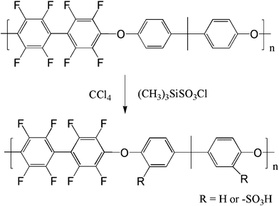 | ||
| Scheme 1 Synthesis of SFPAEs. | ||
| Sample | Molar ratio of ClSO3Si(CH3)3 to polymer repeat unit | IEC (meq g−1) | η (dL g−1) | Water uptake (%) | Swelling ratio (%) | ||
|---|---|---|---|---|---|---|---|
| 22 °C | 60 °C | 22 °C | 60 °C | ||||
| SFPAE-0.91 | 2.5 | 0.9 | 0.63 | 17 | 21 | 8 | 12 |
| SFPAE-1.11 | 3.0 | 1.1 | 0.67 | 21 | 25 | 11 | 15 |
| SFPAE-1.38 | 3.5 | 1.4 | 0.63 | 35 | 42 | 16 | 20 |
| SFPAE-1.72 | 5.0 | 1.8 | 0.57 | 48 | 59 | 19 | 25 |
| SFPAE-2.49 | 6.0 | 2.5 | 0.70 | 76 | 103 | 31 | 38 |
2.4 Membrane preparation
The SFPAEs were dissolved in N,N'-dimethylacetamide (DMAc) solution at approximately 8 wt/vol% and cast on a glass plate, dried at 60 °C for 12 h under ambient pressure, and then dried at 120 °C under vacuum for 24 h. The membranes were removed from the casting plate and immersed in a 1 M H2SO4 solution at 80 °C for 1 h. After acidification, the film was washed continuously with deionized water at 80 °C until the successive wash solutions were neutral (pH 7.0). Samples were stored in deionized water at room temperature until further use.2.5 Characterization
The intrinsic viscosities of the samples were measured in 1-methyl-2-pyrrolidinone (NMP) containing 0.05 M LiBr at room temperature using a Ubbelohde viscometer. The thermal stability of the polymers was analyzed using a Q50 TGA (TA Instruments Corp., New Castle, DE, USA). The temperature was increased from room temperature to 120 °C and held for 30 min., and then increased to 800 °C at a heating rate of 10 °C min−1 under N2 atmosphere. FTIR spectra were recorded on a Bruker (Bruker Optics, Inc., Billerica, MA, USA) Vertex FTIR spectrometer. 1H NMR was obtained using a Bruker (Bruker BioSpin Corporation, Billerica, MA, USA) AV-300 NMR instrument and the chemical shifts were listed in parts per million (ppm) downfield from tetramethylsilane (TMS). The mechanical properties were measured on an Instron (Norwood, MA, USA) 5866 universal testing machine at room temperature.The ion exchange capacity (IEC) was measured as follows: dried membrane was weighed and immersed in a 1 M Na2SO4 solution for 24 h to deprotonate the sulfonic acid groups and form their corresponding sodium salt. The resulting acidic solution was titrated with a KOH solution (0.1 M) using phenolphthalein pH indicator, until a pink color persisted in solution. The IEC was calculated as a function of the added KOH solution from:
 | (1) |
where Wd is the weight of the dry membrane, ΔVKOH is the consumed volume of KOH solution and CKOH is the concentration of KOH solution.
The water uptake of the membranes was defined as the weight ratio of the absorbed water to that of the dry membrane. The swelling ratio was described as the linear expansion ratio of wet membrane. These quantities were calculated via:
 | (2) |
 | (3) |
where Md and Mw are the weight of membranes before and after water absorption, respectively; Ld and Lw are the length of membranes before and after water absorption, respectively.
The proton conductivities of membranes were measured by two-probe electrochemical impedance spectroscopy (EIS) using a Solartron 1260A frequency response analyzer.23 The conductivity measurements were conducted with the membranes submerged in deionized water at 22 °C or 60 °C. The conductivity (σ) was calculated from the impedance plot according to the area available for membrane conducting (A) and the distance between electrodes (d), σ = d/RA, where the resistance R was derived from the intercept of the low frequency complex impedance with the Re (Z') axis.
The VO2+ permeability was measured in a membrane-separated cell using a method similar to a previously established procedure.24 20 mL of 1.7 M VOSO4 in 2.5 M H2SO4 solution was introduced into one reservoir and 20 mL of 1.7 M MgSO4 in 2.5 M H2SO4 solution was introduced into the other reservoir of a membrane separated cell. MgSO4 was used to equalize the osmotic pressure between compartments. The two solutions were continuously magnetically stirred at room temperature. Samples of the MgSO4 solution were taken at a regular time intervals and the concentration of VO2+ was measured with a Varian Cary 100 Scan UV-visible spectrophotometer. A calibration curve of VO2+ concentration and VO2+ absorbance at 763 nm in a UV-vis spectrum, Fig. S2 (ESI†), showed that the concentration was linearly related to absorbance for the concentration range of interest in this work. The VO2+ permeability (D) was calculated from:
 | (4) |
where VB is the volume of MgSO4 solution, CB is the concentration of permeated VO2+ ion in the MgSO4 compartment, t is time, A is membrane area, L is membrane thickness, and CA is the initial concentration of VOSO4, which is 1.7 M in this case.
The VRFB cell performance was measured in the same apparatus as previously reported (Fig. S3†).20 The anolyte was 50 mL of 1.7 M VO2+ in 3.3 M H2SO4 solution and the catholyte was 50 mL of 1.7 M V3+ in 3.3 M H2SO4 solution. Membrane thickness was 55–64 μm. In the first 6 cycles, the discharge rate capability of the cell with different current densities of 100, 75, 50 and 25 mA cm−2 was evaluated, where the cell was charged to 1.7 V at 50 mA cm−2 and then cycled between 1.25 V (∼10% SOC) and 1.6 V (∼90% SOC). The coulombic efficiency (CE), voltage efficiency (VE) and energy efficiency (EE) were calculated from:
 | (5) |
 | (6) |
 | (7) |
where Id is the discharging current, Ic is the charging current, Vd is the discharge voltage, Vc is the charge voltage.
3. Results and discussion
3.1 Polymer synthesis and membrane properties
Fluorinated poly(arylene ether) (FPAE) copolymers were successfully synthesized by reacting decafluorobiphenyl and biphenol A at room temperature for 24 h. Literature sources usually quote 80 °C for this reaction without crosslinking,22,25 however the high temperature was not needed to obtain robust membranes in our experience. The sulfonation reaction was monitored by 1H NMR as shown in Fig. S4 (ESI†). A peak appeared at 7.69 ppm for SFPAE compared to FPAE indicating sulfonate attachment to the aromatic ring. Furthermore, a broad peak from 4.12 ppm to 4.20 ppm was observed for SFPAE which originated from the proton of the sulfonic acid group, but was not observed in metal neutralized-form samples.25 FTIR analysis (Fig. S5 of ESI†) revealed a new peak at 1090 cm−1 for SFPAE samples as compared to the FPAE base polymers, which is characteristic of aromatic sulfonate groups. Both 1H NMR and FTIR demonstrate the successful sulfonation of the FPAE backbone.SFPAEs with ion exchange capacities (IECs) ranging from 0.9 to 2.5 meq g−1 were synthesized by varying the ratio of trimethylsilyl chlorosulfonate to the FPAE repeat unit as listed in Table 1. As expected, higher molar ratios of trimethylsilyl chlorosulfonate resulted in higher IEC samples. The intrinsic viscosities (IVs) of SFPAEs were measured using a procedure to minimize the polyelectrolyte effect according to literature sources.26,27 Similar IVs were found for SFPAEs regardless of IEC as shown in Table 1, reflecting the similar molecular weight of this set of polymers and the absence of side reactions during sulfonation.
The water uptake and swelling ratio of the samples increased with increasing IEC and temperature, Table 1. The water uptake values of SFPAEs were comparable to other sulfonated poly(arylene ether)s reported with similar IEC values.28 The water uptake, in combination with the IEC of the polymer, plays a significant role in the proton conductivity of the membrane. However, high water uptake usually leads to excess swelling of the membrane which causes a decrease in mechanical properties and an increase in permeability of the sample. As can be seen in Fig. 1, both the yield stress and yield strain decreased with the increasing IEC and water uptake due to the absorbed water plasticizing the polymer. In VRFBs, membranes must withstand the impact of flowing electrolyte through the cell and the cyclic stresses of charge/discharge cycling. SFPAEs had higher tensile modulus than N212 except SFPAE-2.49, which swelled too much when exposed to liquid water.
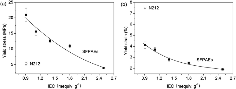 | ||
| Fig. 1 Mechanical properties of SFPAEs and N212: (a) yield stress; (b) yield strain. | ||
The proton conductivities of SFPAEs and N212 membranes are shown in Fig. 2. A trend similar to the water uptake values was found for conductivity, which increased with increasing IEC or temperature. SFPAE-1.8 had a proton conductivity of 61 mS cm−1 at room temperature, which was slightly lower than 69 mS cm−1 for N212 under the same conditions. When the temperature was increased to 60 °C, the proton conductivities of SFPAEs nearly doubled. The operation temperature of a VRFB is limited by the thermal stability of vanadium electrolyte, which is usually less than 60 °C depending on the concentration of vanadium sulfate and sulfuric acid. A further increase in the IEC of the material resulted in higher proton conductivity than N212. SFPAE-2.5 had the highest proton conductivity among all of the samples tested, 92 mS cm−1 at room temperature and 150 mS cm−1 at 60 °C.
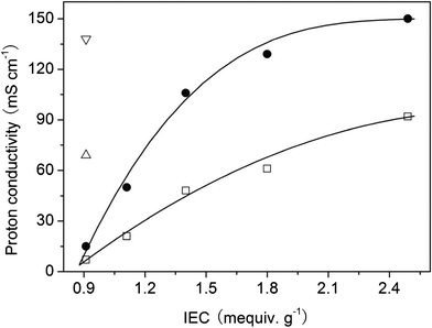 | ||
| Fig. 2 Proton conductivities of SFPAEs (□ at 22 °C and ● at 60 °C) and N212 (Δ at 22 °C and ∇ at 60 °C). | ||
Due to the low IECs and water uptakes of SFPAE-0.9 and SFPAE-1.1 membranes, no vanadium permeability was observed through these samples over 48 h. As the IEC of the SFPAE samples was increased, the permeability of VO2+ species increased accordingly (Fig. 3). The VO2+ permeability of N212 was 3.2 × 10⁻¹² m2 s−1, similar to that of NAFION® 117.4 SFPAE-1.4 and SFPAE-1.8 membranes had much lower VO2+ permeability than N212 while the SFPAE-2.5 sample had a slightly higher VO2+ permeability than N212. These results are in agreement with the water uptake of the samples.
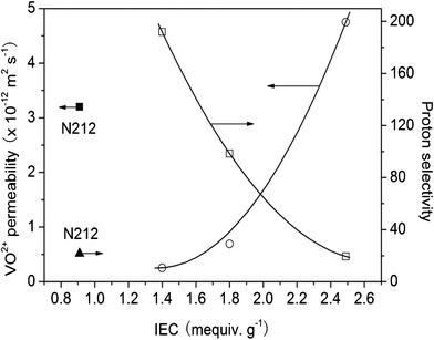 | ||
| Fig. 3 VO2+ permeabilities (○) and proton selectivities (□) of SFPAEs. Values for N212 are shown for comparison. | ||
Proton selectivity was defined as the ratio of proton conductivity (mS cm−1) to VO2+ permeability (m2 s−1). Fig. 3 shows that the proton selectivity of the SFPAE samples decreased as the IEC of the samples was increased. N212 and SFPAE-2.5 had low proton selectivity as compared to SFPAE-1.4 and SFPAE-1.8. Since SFPAE-0.9 and SFPAE-1.1 had very low VO2+ permeability, their proton selectivity should be extremely high. However, their conductivity is not high enough for effective VRFB performance at reasonable current densities. SFPAE-1.8 had comparable proton conductivity to N212 but much higher proton selectivity than N212, which makes it a promising prospect for VRFB application. The low proton selectivity of NAFION® membranes was likely due to their highly developed hydrophilic-hydrophobic nanophase separation, while aromatic membranes are known to have smaller ionic domain structures which prevents diffusion of methanol and other species.29,30 Considering the trade-off between proton conductivity and VO2+ permeability, we selected SFPAE-1.8 as the most suitable membrane for VRFB studies.
3.2 VRFB cell performance
Fig. 4(a) shows the charge and discharge curves of VRFBs with SFPAE-1.8 and N212 membranes. The VRFB with a SFPAE-1.8 membrane had slightly lower charging voltage while having higher discharging voltage and longer discharge time. These advantages can be more obviously observed in the coulombic efficiencies (CE) and voltage efficiencies (VE) of the cell, Fig. 4(b) and (c), respectively. It can be seen that the CEs of the VRFB with SFPAE-1.8 membrane are higher than 98%, much greater than those of the VRFB with a N212 membrane. The VEs of the VRFB with a SFPAE-1.8 membrane are similar or slightly higher than those of the VRFB with the N212 membrane (>92% even at a discharge current density of 100 mA cm−2). These cell performance metrics are well-correlated to the membrane properties where SFPAE-1.8 has comparable conductivity to N212 but much lower VO2+ permeability.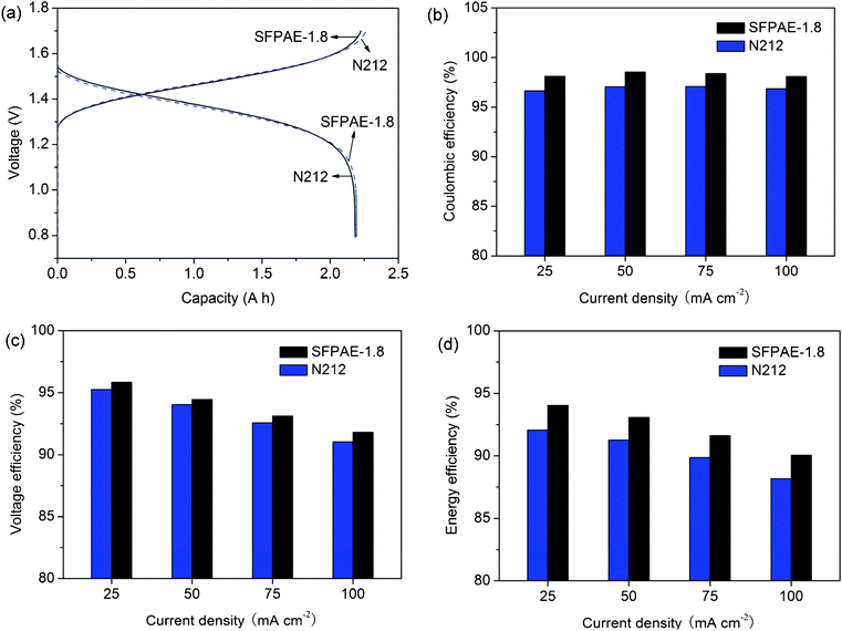 | ||
| Fig. 4 Cell performance of VRFBs with N212 and SFPAE-1.8 membranes: (a) charging (at 50 mA cm−2) and discharging (at 100 mA cm−2) curves; (b) voltage efficiencies (c) coulombic efficiencies (d) energy efficiencies under different discharging current densities. | ||
The energy efficiencies (EE) of VRFBs with SFPAE-1.8 and N212 membranes are shown in Fig. 4(d). Around 2% higher EEs were observed in VRFBs with SFPAE-1.8 membranes compared to those of the VRFB with a N212 membrane over the range of current densities tested. The EEs of VRFBs with SFPAE-1.8 are among the highest (>90%) values for VRFBs reported so far. The high performance of these cells is due to the superior proton conductivity and low vanadium permeability of these membranes and the polymer's stable chemical structure which does not decrease the coulombic efficiency during operation due to side reactions. The computed EE and CE values are affected by membrane permeability as well as the details of the VRFB system configuration. Vanadium ions with different valences may transport across the membrane due to 1) concentration gradient, 2) convective flow, 3) electric potential gradient, 3) pressure gradient, or 4) osmotic pressure gradient. Thus, measurements of efficiency during VRFB testing are determined by a net effect of these transport modes, which are dependent on membrane properties as well as the cell design and device operating parameters. Membrane permeability was measured for solutions under the same pressure, but the pressures in the positive and negative solution sides in the operating VRFB are not the same at the same pumping flow rate due to the different viscosities of the positive and negative solutions. Given these device operation caveats, for identical testing conditions used for the different samples in this work, membranes with low vanadium ion diffusivity show higher CE, which supports a systematically higher performance with the SFPAE membrane tested compared to the NAFION® control membranes.
Fig. 5(a) compares the cyclic properties of VRFBs with SFPAE-1.8 and N212 membranes. The cell performance benefits of the SFPAE membrane were revealed by its low capacity fade during cycling due to the sample's low VO2+ permeability. The capacity of the VRFB with SFPAE-1.8 membrane decreased by 1.1 mA h per cycle, which is about 7 times lower than that of the VRFB with N212 membrane (7.6 mA h per cycle). The low capacity fade of the SFPAE membrane can extend the required maintenance period of the system, leading to a reduction of the VRFB system cost. In our previous study, S-Radel membrane showed a capacity loss of half that of NAFION® and only lasted for 40 cycles in VRFB charge–discharge testing because of its low stability.19 As demonstrated by the ex-situ soaking test, SFPAEs had significantly improved oxidative stability compared to their non-fluorinated analogs. The stability measurements are in agreement with the VRFB cyclic tests shown in Fig. 5(b). The CE, VE and EE of the VRFB with SFPAE-1.8 membrane did not decrease even after 75 cycles (about 8 h per cycle). Extended longevity testing is under way.
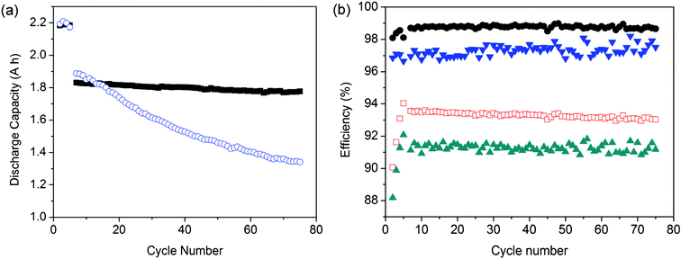 | ||
| Fig. 5 Cyclic performance comparison of VRFBs with N212 and SFPAE-1.8 membranes at 50 mA cm−2: (a) capacity as a function of cycle number (○: N212; ●: SFPAE-1.8); (b) coulombic efficiency (▼: N212; □: SFPAE-1.8) and energy efficiency (▲: N212; □: SFPAE-1.8) with cycle number. | ||
3.3 Membrane stability
The thermal weight loss curves of SFPAEs in H+ form and Na+ form are shown in Fig. S6 and Fig. S7 (ESI†), respectively. In H+ form, SFPAEs showed two-step decomposition, the first of which was the decomposition of the sulfonic acid group and the second was the degradation of the backbone.31 The 5% weight loss temperature was greater than 250 °C, far beyond the operation window of VRFBs. Generally, H+ form membranes show decreased thermal stability compared to their metal neutralized-form analogs, but the thermal stability of the membranes is greatly improved with metal cation replacement (Fig. S7†), which readily occurs in the VRFB electrolytes.In our previous studies, the S-Radel membranes suffered from severe color change in ex-situ V5+ immersion testing, which is related with the material's chemical degradation and subsequent short lifetime in VRFB operation.19,20 Here we immersed N212, SFPAE-1.8, SFPAE-1.4 and S-Radel-1.9 membranes in 0.1 M and 1.7 M VO2+ solutions at 40 °C for a number of days. In 1.7 M VO2+ solutions, the color change of the solutions as an indicator of degradation of the polymer was difficult to discern. However, the color change of the solution indicating degradation of the polymer was obvious in 0.1 M VO2+ solutions. From Fig. 6 it can be seen that the solutions of SFPAE-1.8 (31 d) and SFPAE-1.4 (79 d) showed a very slight color change. In comparison, the solution of S-Radel-1.9 (40 d) turned green, the color of a VO2+/VO2+ mixture, as validated by UV-vis.20 Since color change is an indication of the polymer being oxidized and the vanadium species undergoing reduction, SFPAE samples showed significantly improved stability compared to S-Radel-based materials. Furthermore, SFPAE membranes did not suffer mechanical breakage during the immersion tests while S-Radel-1.9 broke into multiple pieces during immersion.7 These ex-situ tests demonstrate the high stability SFPAEs due to their fluorinated structure. We have not been able to determine the exact mechanism of chemical attack of vanadium species on these polymers, but we speculate that the strong oxidizing power of V5+ is one of the major contributors to polymer degradation in VRFBs. The electron-withdrawing power of fluorine shields the aromatic backbone rendering fluorinated aromatic polymers more stable than their non-fluorinated analogs.
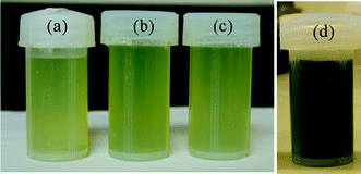 | ||
| Fig. 6 Membrane samples immersed in 0.1 M VO2+ with 5.0 M total sulfate solutions at 40 °C: (a) N212, after 140 d; (b) SFPAE-1.8, after 31 d; (c) SFPAE-1.4, after 79 d; (d) S-Radel-1.9, after 40 d. | ||
4. Conclusions
Chemically stable membranes based on partially fluorinated sulfonated poly(arylene ether) (SFPAE) copolymers with varying ion exchange capacities showed improved performance in vanadium redox flow battery (VRFB) devices compared to NAFION® N212 membranes. SFPAE with an IEC of 1.8 meq g−1 which had comparable proton conductivity but much lower VO2+ permeability compared to N212, showed coulombic efficiency (CE) higher than 98%, voltage efficiency (VE) higher than 92%, and energy efficiency (EE) higher than 90% at discharge current densities ranging from 25 mA cm−2 to 100 mA cm−2. These performance metrics were higher than those of a VRFB with N212 under the same conditions and reflected the increased proton selectivity of the SFPAE membranes. The capacity fade rate of a VRFB with the SFPAE-1.8 membrane during charge/discharge cycling was 1.1 mA h per cycle, which was about 7 times lower than that of a VRFB with a N212 membrane. Increased cycle number was achieved using SFPAE-1.8 membrane as compared to our previous S-Radel 1.9 meq g−1 membrane which emphasizes the improved stability of the fluorinated aromatic polymer structure.Acknowledgements
The work is supported by the Office of Electricity (OE Delivery & Energy Reliability (OE), U.S. Department of Energy (DOE) under contract DE-AC05-76RL01830. The authors thank Sean Nuñez for assistance with manuscript preparation.References
- A. Z. Weber, M. M. Mench, J. P. Meyers, P. N. Ross, J. T. Gostick and Q. H. Liu, J. Appl. Electrochem., 2011, 41, 1137–1164 CrossRef CAS.
- B. Tian, C. W. Yan and F. H. Wang, J. Membr. Sci., 2004, 234, 51–54 CrossRef CAS.
- J. Y. Xi, Z. H. Wu, X. P. Qiu and L. Q. Chen, J. Power Sources, 2007, 166, 531–536 CrossRef CAS.
- D. Y. Chen, S. J. Wang, M. Xiao and Y. Z. Meng, J. Power Sources, 2010, 195, 2089–2095 CrossRef CAS.
- D. B. Xing, S. H. Zhang, C. X. Yin, B. G. Zhang and X. G. Jian, J. Membr. Sci., 2010, 354, 68–73 CrossRef CAS.
- H. Z. Zhang, H. M. Zhang, X. F. Li, Z. S. Mai and J. L. Zhang, Energy Environ. Sci., 2011, 4, 1676–1679 CAS.
- B. Schwenzer, J. L. Zhang, S. W. Kim, L. Y. Li, J. Liu and Z. G. Yang, ChemSusChem, 2011, 4, 1388–1406 CrossRef CAS.
- X. G. Teng, Y. T. Zhao, J. Y. Xi, Z. H. Wu, X. P. Qiu and L. Q. Chen, J. Power Sources, 2009, 189, 1240–1246 CrossRef CAS.
- C. K. Jia, J. G. Liu and C. W. Yan, J. Power Sources, 2012, 203, 190–194 CrossRef CAS.
- Q. T. Luo, H. M. Zhang, J. Chen, D. J. You, C. X. Sun and Y. J. Zhang, J. Membr. Sci., 2008, 325, 553–558 CrossRef CAS.
- J Zeng, C. P. Jiang, Y. H. Wang, J. W. Chen, S. F. Zhu, B. J. Zhao and R. L. Wang, Electrochem. Commun., 2008, 10, 372–375 CrossRef CAS.
- X. F. Li, H. M. Zhang, Z. S. Mai, H. Z. Zhang and I. Vankelecom, Energy Environ. Sci., 2011, 4, 1147–1160 CAS.
- M. A. Hickner, H. Ghassemi, Y. S. Kim, B. R. Einsla and J. E. McGrath, Chem. Rev., 2004, 104, 4587–4612 CrossRef CAS.
- T. J. Peckham and S. Holdcroft, Adv. Mater., 2010, 22, 4667–4690 CrossRef CAS.
- Y. A. Elabd and M. A. Hickner, Macromolecules, 2011, 44, 1–11 CrossRef CAS.
- B. Bae, T. Yoda, K. Miyatake, H. Uchida and M. Watanabe, Angew. Chem., Int. Ed., 2010, 49, 317–320 CrossRef CAS.
- N. W. Li, C. Y. Wang, S. Y. Lee, C. H. Park, Y. M. Lee and M. D. Guiver, Angew. Chem., 2011, 123, 9324–9327 CrossRef.
- B. S. Pivovar, Y. Wang and E. L. Cussler, J. Membr. Sci., 1999, 154, 155–162 CrossRef CAS.
- S. Kim, J. L. Yan, B. Schwenzer, J. L. Zhang, L. Y. Li, J. Liu, Z. G. Yang and M. A. Hickner, Electrochem. Commun., 2010, 12, 1650–1653 CrossRef CAS.
- S. Kim, T. B. Tighe, B. Schwenzer, J. L. Yan, J. L. Zhang, J. Liu, Z. G. Yang and M. A. Hickner, J. Appl. Electrochem., 2011, 41, 1201–1213 CrossRef CAS.
- C. H. Lee, S. Y. Lee, Y. M. Lee, S. Y. Lee, J. W. Rhim, O. Lane and J. E. McGrath, ACS Appl. Mater. Interfaces, 2009, 1, 1113–1121 CAS.
- F. Schonberger, A. Chromik and J. Kerres, Polymer, 2010, 51, 4299–4313 CrossRef.
- T. Saito, M. D. Merrill, V. J. Watson, B. E. Logan and M. A. Hickner, Electrochim. Acta, 2010, 55, 3398–3403 CrossRef CAS.
- E. Wiedemann, A. Heintz and R. N. Lichtenthaler, J. Membr. Sci., 1998, 141, 215–221 CrossRef CAS.
- D. Y. Chen, S. J. Wang, M. Xiao, Y. Z. Meng and A. S. Hay, J. Mater. Chem., 2011, 21, 12068–12077 RSC.
- J. Yang, Y. X. Li, A. Roy and J. E. McGrath, Polymer, 2008, 49, 5300–5306 CrossRef CAS.
- Y. X. Li, F. Wang, J. Yang, D. Liu, A. Roy, S. Case, J. Lesko and J. E. McGrath, Polymer, 2006, 47, 4210–4217 CrossRef CAS.
- N. W. Li, S. Y. Lee, Y. L. Liu, Y. M. Lee and M. D. Guiver, Energy Environ. Sci., 2012, 5, 5346–5355 CAS.
- K. D. Kreuer, J. Membr. Sci., 2001, 185, 29–39 CrossRef CAS.
- M. A. Hickner and B. S. Pivovar, Fuel Cells, 2005, 5, 213–229 CrossRef CAS.
- Y. Zhang, G. Zhang, Y. Wan, C. J. Zhao, K. Shao, H. T. Li, M. M. Han, J. Zhu, S. Xu, Z. G. Liu and H. J. Na, J. Polym. Sci., Part A: Polym. Chem., 2010, 48, 5824–5832 CrossRef CAS.
Footnote |
| † Electronic supplementary information (ESI) available. See DOI: 10.1039/c2ra20834b/ |
| This journal is © The Royal Society of Chemistry 2012 |
