Tunability of structure from ordered to disordered and its impact on ionic conductivity behavior in the Nd2−yHoyZr2O7 (0.0 ≤ y ≤ 2.0) system
Farheen N.
Sayed
a,
Dheeraj
Jain
a,
B.P.
Mandal
a,
C. G. S.
Pillai
a and
A. K.
Tyagi
*b
aChemistry Division, Bhabha Atomic Research Centre, Mumbai, India 400085
bDr A. K. Tyagi, Chemistry Division, Bhabha Atomic Research Centre, Mumbai, 400 085. E-mail: aktyagi@barc.gov.in; Fax: 0091-22-25505151; Tel: 0091-22-22592328
First published on 28th June 2012
Abstract
The present paper describes a detailed investigation of the nature of the order–disorder transition in the Nd2−yHoyZr2O7 system, over the entire composition range (0.0 ≤ y ≤ 2.0), using a combination of diffraction and spectroscopic analysis techniques. The complete series of solid solutions has been prepared by the gel combustion technique followed by high temperature sintering. Detailed structural characterization of the prepared samples using X-ray diffraction studies confirmed their single-phase solid solution formation throughout the series, as well as identifying the transformation of the system from an ordered pyrochlore structure (0.0 ≤ y ≤ 0.8) to a disordered fluorite-type structure (0.8 < y ≤ 2.0). Micro-Raman studies further supported the structural information. Micro-structural studies by SEM revealed dense products with uniform grain distribution in these materials. Comprehensive studies were performed to investigate the ionic conductivity behavior of these solid solutions in correlation with the structural transformations using AC impedance spectroscopy. A detailed analysis of ionic conductivity and related parameters, such as activation energies, etc. corresponding to individual conduction mechanisms such as bulk and grain boundary conduction, clearly correlated the effect of structural transformation on these charge transport properties. The composition Nd1.2Ho0.8Zr2O7 with the pyrochlore structure has been found to show the highest ionic conductivity in the entire series, which has been attributed to a combined effect of increasing carrier concentration and their preferred movement through an ordered array of vacant anion sites.
1. Introduction
Pyrochlores are a class of materials that has received much attention in recent years, due to their versatile applications. Their properties, such as semi-conducting behavior,1 ionic conductivity,2,3 ferromagnetism,4 luminescence,5,6 radiation stability,7,8etc. have been explored in their respective fields of application. Oxide pyrochlores find applications in solid oxide fuel cells as electrolytes9,10 and gas sensors.11 The formula for an ideal oxide pyrochlore is A2B2O7, which is more correctly written as A2B2O(1)6O(2), where O(1) and O(2) correspond to crystallographically distinct oxygen atoms. Pyrochlore oxides belong to the Fd-3m space group, which has a lattice parameter that is double that of the fluorite structure (Fm-3m). Among the majority of the known pyrochlore oxides under investigation, the III-IV pyrochlores are the ones in which the A3+ (larger) and B4+ (smaller) ions occupy the 16d (1/2, 1/2, 1/2) and 16c (0, 0, 0) positions, respectively. The two crystallographically distinct oxide ions, O(1) and O(2), are present at the 48f (x, 1/8, 1/8) and 8b (3/8, 3/8, 3/8) positions, respectively. The third oxygen position, O(3), which is vacant in this structure, would be required to complete the anion arrangement in a fluorite lattice. This vacant anion site occurs at the position 8a (1/8, 1/8, 1/8). The A-site cations are eight-fold coordinated, located within scalenohedra (distorted cubes), whereas the B-site cations are six-coordinated, located within trigonal antiprisms. All anions are tetrahedrally coordinated: the 8a anion site is surrounded by four B cations and the 8b anion site by four A cations. The 48f anion site is surrounded by two A and two B cations, which are slightly displaced from the center of the tetrahedral site towards the unoccupied 8a site. The magnitude of this displacement is represented by a positional parameter ‘x’, for the anion at the 48f site, which is 0.375 for an ideal fluorite structure.12 The larger bond distance between the A cations and oxygen will, accordingly, contribute to the displacement of O(1) as well. Hence the cationic radii ratio governs the pyrochlore structure. For A23+B24+O7 pyrochlores, the A3+ cation can be as small as Lu3+ (0.977 Å) or as large as Bi3+ (1.17 Å), while the radii of the B4+ cations fall between 0.58 and 0.72 Å.9 The stability of a pyrochlore (A2B2O7) can be predicted by the tolerance factor, which is defined as the ratio of the ionic radius of the A- and B-site cation according to the following equation:| Tolerance factor = Ionic radiusA-ion/Ionic radiusB-ion |
The tolerance factor (tf) for pyrochlores from the lanthanide family is in general within (1.4 < tf < 1.9). Pyrochlores are closely related to the fluorite structured materials but conduct electricity at lower temperatures. This behavior has been attributed to the presence of vacancies, which are the intrinsic structural features of these materials. It is to be noted that the conductivity varies drastically upon transformation of the ordered pyrochlore to the disordered structure. This order–disorder transition from pyrochlore to fluorite can be introduced merely by changing the composition,12 increasing the temperature,13,14 applying pressure15 and/or by high-energy irradiation.16,17 This clearly establishes the fact that study of disorder in pyrochlores is an important factor governing its structural properties, which in turn influences its electrical and other properties. There have been studies to correlate the ionic conductivity with the disorder prevailing in the pyrochlore structure.18,19 Ionic conductivity is also reported to be notably dependent on the preparation routes of the ceramics.20 Soft chemical routes, such as gel-combustion, can yield soft-agglomerated nanopowders with superior powder properties, which in turn lead to high-density material with a uniform microstructure upon sintering, and thereby exhibit better ionic conductivity.
In the present investigation, an attempt has been made to vary the A-site cation in the Nd2Zr2O7 pyrochlore by substituting Ho3+ ions so as to gradually transform the structure from an ordered pyrochlore (Nd2Zr2O7) to a completely disordered one (Ho2Zr2O7) through an order–disorder transition. Detailed X-ray diffraction (XRD) analysis, supported by Raman spectroscopic studies, has been performed on Nd2−yHoyZr2O7 solid solutions (0.0 ≤ y ≤ 2.0) to gain an insight into the structural changes occurring upon gradual Ho3+ substitution for Nd3+. Rietveld analysis was performed on the powder X-ray diffraction (XRD) data of these solid solutions, and the results are described herein. AC impedance studies have been performed on these materials to correlate the trend in ionic conductivity with the disorder induced in the structure upon increasing Ho3+ substitution.
2. Experimental
2.1 Reagents
For the synthesis of Nd2−yHoyZr2O7 (0.0 ≤ y ≤ 2.0) solid solutions, analytical reagent (AR) grade powders of Nd2O3, Ho2O3, ZrO(NO3)2·H2O, and glycine (NH2CH2COOH) were used as the starting reagents.2.2 Synthesis of Nd2−yHoyZr2O7 (0.0 ≤ y ≤ 2.0) solid solutions
To ensure the removal of adsorbed moisture and other gases, Nd2O3 and Ho2O3 were preheated at 1073 K for 12 h. The net oxidizing valencies of niodium nitrate, holmium nitrate and zirconium oxynitrate, as well as the reducing valency of the fuel (glycine), were calculated using the valencies of the individual elements. The ratio of the oxidizing and reducing valencies should be unity on the basis of stoichiometry.21 For this system, the ratio of the amounts of metal nitrates and oxynitrates to that of glycine was found to be 1![[thin space (1/6-em)]](https://www.rsc.org/images/entities/char_2009.gif) :4.5. However, a fuel deficient ratio compared to the stoichiometry ratio was taken for the synthesis, as it is known to give soft agglomerated nanopowders, which further helps to achieve higher sinterability. To synthesize different compositions in Nd2−yHoyZr2O7 (0.0 ≤ y ≤ 2.0), the required amounts of the reactants were weighed and dissolved in the minimum volume of dilute nitric acid and appropriate amounts of fuel (glycine) were added to it. Highly viscous liquids, hereafter known as “precursors”, resulted after thermal dehydration of these solutions around 353 K. The temperature of the hot plate was raised to 523 K as soon as the viscous liquid was formed. The precursors swelled and auto ignited, with rapid evolution of a large volume of gases to produce voluminous powders. To ensure complete removal of the decomposition products and excess carbon, the as-synthesized powders were calcined at 1000 K in static air for 30 min.
:4.5. However, a fuel deficient ratio compared to the stoichiometry ratio was taken for the synthesis, as it is known to give soft agglomerated nanopowders, which further helps to achieve higher sinterability. To synthesize different compositions in Nd2−yHoyZr2O7 (0.0 ≤ y ≤ 2.0), the required amounts of the reactants were weighed and dissolved in the minimum volume of dilute nitric acid and appropriate amounts of fuel (glycine) were added to it. Highly viscous liquids, hereafter known as “precursors”, resulted after thermal dehydration of these solutions around 353 K. The temperature of the hot plate was raised to 523 K as soon as the viscous liquid was formed. The precursors swelled and auto ignited, with rapid evolution of a large volume of gases to produce voluminous powders. To ensure complete removal of the decomposition products and excess carbon, the as-synthesized powders were calcined at 1000 K in static air for 30 min.
2.3 Material characterization
The products were characterized by powder XRD using monochromatized Cu-Kα radiation on an X-ray diffractometer (model PW 1927, Philips) using silicon as an external standard for correction due to instrumental broadening. The XRD patterns revealed the as-synthesized products to be in the nanosize regime, but the superstructure peaks of the pyrochlore phase were not visible. The powders were therefore further compacted into small pellets and sintered at 1723 K for 12 h in a static air atmosphere to get the final products. These samples were taken for further analysis thereafter.Rietveld refinement was performed on diffraction patterns of all the single phase samples using the Fullprof package, and cell parameters were subsequently calculated.22 The microstructure of the sintered pellets was investigated using a scanning electron microscope (model: AIS 210, Mirero Inc., Seongnam-si, South Korea) after sputter coating the pellets with a thin layer of gold. Raman spectroscopic measurements were performed on a micro/macro-Raman spectrometer (model: LABRAM-1, France) using the 488 nm line of an Ar+ ion laser for excitation. The scattered Raman signal was collected using a single-monochromator spectrometer equipped with a Peltier-cooled CCD detector in the backscattering geometry.
Alternating-current (AC) impedance measurements were performed on sintered samples using an impedance gain phase analyzer (model SI 1260, Solartron, UK) in the frequency range 1 MHz to 1 Hz. High density sintered pellets (∼95% of the theoretical density) were used for these measurements. An ac voltage amplitude of 200 mV with a zero direct-current (dc) bias was applied across the two flat ends of these cylindrical pellets (7.5–8 mm diameter; 0.9–1.0 mm thickness) during each measurement. Measurements were carried out in the temperature range 523 to 1073 K in the static air atmosphere. A conducting platinum paste was applied at both the flat surfaces of the samples, followed by annealing at 1073 K, before placing them into an indigenously designed and fabricated impedance cell. Z plot 2.9b (serial no.: Z plot: 7471-2) and Z view 2.9b (serial no.: Z plot: 7471-2) software was used to collect and analyze the impedance spectra.
3. Results and discussion
In order to determine the phase formation of Nd2−yHoyZr2O7 (0.0 ≤ y ≤ 2.0) solid solutions and to characterize their structure, detailed X-ray diffraction studies have been carried out. The room temperature X-ray diffraction patterns of all the sintered samples are shown in Fig. 1A. The pyrochlore structure is a superstructure of a fluorite-like array of atoms. Therefore, its diffraction pattern consists of a set of strong intensity lines, representative of the average fluorite structure, along with an additional set of weak superstructure reflections. The superstructure peaks contain all the information on the associated structural transformation and ordering process.23 It can be clearly observed that all the samples in the studied series show high intensity peaks, with all even Miller indices, such as (222), (400), (622), etc., representing the average fluorite-type unit cells. The superstructure peaks with all odd Miller indices (111), (311), (331), etc. are characteristic of the pyrochlore structure. The intensity of these characteristic peaks depends upon the size and atomic number of the cation at the ‘A’ position, and also on the degree of antisite occupation of the cation in the ‘A’ and ‘B’ positions. Since the Z values of the two cations are comparable with respect to Zr, the predominant reason for the decreasing intensity of the superstructure reflections comes mainly from the disorder in the A and B cations. Dickson et al.,24 have reported that the intensity of the (111) reflection is most sensitive to the position of the x-parameter of 48f oxygen. The x-parameter of 48f oxygen increases from 0.3125 to 0.375 with increasing disorder in the system, and the intensities of the characteristic pyrochlore superstructure peaks gradually diminish. It can be observed from Fig. 1A that the superstructure peaks start diminishing in intensity as the concentration of Ho3+ increases, suggesting transition of the structure from an ordered pyrochlore to defect fluorite. Therefore, the end members Nd2Zr2O7 and Ho2Zr2O7 crystallize into the completely ordered pyrochlore and defect fluorite structures, respectively. This also agrees with the theoretical calculations, where it has been shown that the ratio of the ionic radii of A3+ and B4+ should be between 1.4 and 1.8 for the stability of the ordered pyrochlore structure.25 In the present solid solutions, the ionic radii for Nd3+ (in 8 coordinated environment), Ho3+ (in 8 coordinated environment) and Zr4+ (in 6 coordinated environment) are 1.109 Å, 1.015 Å and 0.78 Å, respectively.26 The value of the tolerance factor ‘tf’, for the series thus varies from 1.403 to 1.284 for Nd2Zr2O7 to Ho2Zr2O7, respectively, indicating the possibility of an order–disorder transformation on substituting more and more Ho3+ into Nd2Zr2O7, which is in line with our observations from the XRD analysis. Structural analysis was carried out by Rietveld refinement of the diffraction data using program Fullprof-2008. First the scale factor and background parameters were fitted.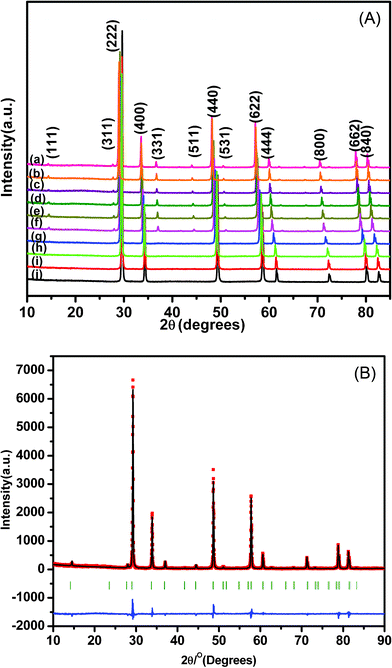 | ||
| Fig. 1 (A) XRD patterns of Nd2−yHoyZr2O7, where y is (a) 0.0 (b) 0.10 (c) 0.20 (d) 0.40 (e) 0.60 (f) 0.8 (g) 1.2 (h) 1.6 (i) 1.8 and (j) 2.0; (B) XRD patterns of Nd1.2Ho0.8Zr2O7. | ||
The diffraction peak profile was fitted with a pseudo-Voigt profile function and Caglioti profile parameters were refined. Absorption and extinction coefficients were not considered during refinement. Oxygen x-parameters were refined for all the samples showing characteristic all odd Miller indices in the XRD pattern. Refinement of the occupancy of cations and anions with stoichiometric constraints did not give rise to a reasonable value during refinement, because of the complexity arising due to the presence of three different cations distributed over two crystallographically distinct sites. A typical refinement profile, the measured X-ray diffraction pattern, difference plot and the calculated peak positions for the composition 10 mol% Ho3+ are shown in Fig. 1B. The results of refinement for the series Nd2−yHoyZr2O7 (0.0 ≤ y ≤ 2.0) are summarized in Table 1. It has been found that the lattice parameter decreases with substitution of Ho3+ (1.015 Å) in place of Nd3+ (1.109 Å) at the A site while going from Nd2Zr2O7 to Ho2Zr2O7. This is clearly reflected in the peak positions, shifting towards higher angles with increasing Ho3+ content, as shown in Fig. 2. This decrease in lattice parameter is linear until 40 mol% Ho3+ (i.e. Nd1.2Ho0.8Zr2O7), but as soon as the structure transforms to defect fluorite, the lattice constant becomes about half of the ordered pyrochlore structure, as shown in Fig. 3. For comparison purposes and to show the trend, the lattice constant values of the compounds in defect fluorite region have been doubled and are shown in the figure. Clearly, the cell parameter decreases linearly with increasing Ho3+ content. It is also noted from Table 1 that the 48f oxygen x-parameter increases with increasing Ho3+ content. As the x-parameter is a sensitive measure of disorder in the anionic sub-lattice, the increasing trend of x with Ho3+ substitution can be interpreted as the gradual transformation of the pyrochlore lattice to the fluorite lattice. In a pyrochlore structure with origin (0, 0, 0) taken at the B site, the 48f oxygen x-parameters are in the range 0.33 to 0.34, which lies within the range 0.3125 to 0.375 of the pyrochlore to fluorite structure. In a perfect pyrochlore, there are three types of sites for anions and vacancies viz. 8a, 8b and 48f, wherein 8b and 48f are occupied by oxygen ions and 8a is vacant. Assuming a totally ordered structure, the B ion has a perfect octahedral coordination and the x-coordinate of the 48f ion in this case would be 0.3125. This has also been well documented in the literature by various authors.27,35 In a perfectly disordered pyrochlore (fluorite-type), the x-coordinate has a value of 0.375, and the A-cations are situated in a regular cubic 8-fold coordination, whereas the B ion is at the centre of a highly distorted octahedron (trigonal antiprism).12 The trend observed in the present series of solid solutions is depicted in Fig. 4, where a near linear increasing trend of the x-parameter with increasing Ho3+ content clearly accounts for the increasing disorder in the structure. Also, from the XRD data a partial intermixing of the cations (in particular Zr4+ and Nd3+) in the lattice is observed.
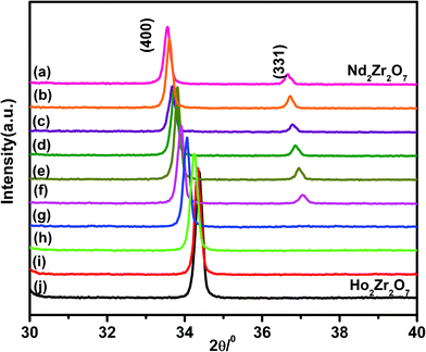 | ||
| Fig. 2 Systematic peak shift in the (400) and (331) peaks of Nd2−yHoyZr2O7, where y is (a) 0.0 (b) 0.10 (c) 0.20 (d) 0.40 (e) 0.60 (f) 0.8 (g) 1.2 (h) 1.6 (i) 1.8 and (j) 2.0. | ||
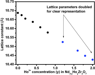 | ||
| Fig. 3 Lattice parameters of Nd2−yHoyZr2O7, where y is (a) 0.0 (b) 0.10 (c) 0.20 (d) 0.40 (e) 0.60 (f) 0.8 (g) 1.2 (h) 1.6 (i) 1.8 and (j) 2.0. | ||
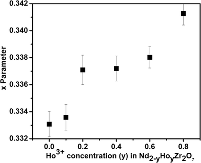 | ||
| Fig. 4 x-Parameters of Nd2−yHoyZr2O7, where y is (a) 0.0 (b) 0.10 (c) 0.20 (d) 0.40 (e) 0.60 (f) 0.8. | ||
| Sample | y = 0.0 | y = 0.10 | y = 0.20 | y = 0.40 | y = 0.60 | y = 0.80 | y = 1.2 | y = 1.6 | y = 1.8 | y = 2.0 |
|---|---|---|---|---|---|---|---|---|---|---|
| Phase | Pyrochlore | Pyrochlore | Pyrochlore | Pyrochlore | Pyrochlore | Pyrochlore | Defect fluorite | Defect fluorite | Defect fluorite | Defect fluorite |
| Space group | Fd-3m | Fd-3m | Fd-3m | Fd-3m | Fd-3m | Fd-3m | Fm3m | Fm3m | Fm3m | Fm3m |
| Lattice constant | 10.6877(1) | 10.6700(1) | 10.6555(4) | 10.6313(4) | 10.6077(1) | 10.5782(2) | 5.2627(2) | 5.2302(4) | 5.2280(9) | 5.2148(4) |
| U | 0.05504 | 0.05058 | 0.10902 | 0.05887 | 0.05017 | 0.08392 | 0.05800 | 0.08847 | 0.04911 | 0.12967 |
| V | −0.07530 | −0.05864 | −0.13792 | −0.07414 | −0.04912 | −0.09769 | −0.07007 | −0.11557 | −0.04824 | −0.11362 |
| W | 0.04178 | 0.03194 | 0.05625 | 0.03857 | 0.02649 | 0.04941 | 0.04317 | 0.06431 | 0.03216 | 0.05855 |
| Asymmetry parameters A1 and A2 | 0.19966 | 0.11296 | 0.13524 | 0.11266 | 0.09591 | 0.02271 | 0.00000 | 0.14605 | 0.08257 | 0.07285 |
| 0.03776 | 0.04659 | 0.04367 | 0.05274 | 0.04688 | 0.03887 | 0.02868 | 0.03560 | 0.03448 | 0.03334 | |
| x-parameter | 0.33308 (94) | 0.33358 (96) | 0.33451 (115) | 0.33720 (93) | 0.33803 (79) | 0.34127 (85) | — | — | — | — |
| Overall B factor | 0.000 | 0.000 | 0.000 | 0.228 | 0.766 | 0.501 | 1.98183 | 1.61700 | 1.49393 | 2.03912 |
| R p | 10.2 | 9.68 | 11.9 | 9.47 | 8.83 | 10.2 | 10.0 | 8.81 | 8.93 | 8.78 |
| R wp | 13.9 | 14.1 | 15.2 | 13.7 | 12.8 | 14.0 | 13.1 | 12.1 | 12.6 | 11.9 |
| R exp | 9.92 | 9.61 | 10.51 | 9.45 | 8.80 | 9.24 | 9.30 | 8.72 | 8.83 | 7.99 |
| χ 2 | 1.96 | 2.15 | 2.10 | 2.09 | 2.12 | 2.28 | 1.99 | 1.94 | 2.02 | 2.20 |
A maximum of about 10% intermixing is observed in all the compositions varying from 0.0 to 0.4, while no significant mixing is observed beyond this.
Typically, occupation of Zr4+ in the Nd3+ site is 0.049, 0.405 and 0.065 for the compositions with y = 0.1, 0.2 and 0.4, respectively. The distribution can be taken into account with the marginal difference in the scattering factor of Nd3+ and Ho3+. Beyond this composition, the refinement of the Zr4+ occupation number leads to no reliable values. Hence, it has been concluded that a maximum 10% distribution of zirconium is apparent in the studied system. Also, it can be suggested that as a sufficient amount of Ho3+ is introduced in the lattice, the lattice preferentially orders with respect to cations, which may be attributed to the formation process.
It may be noted that X-ray diffraction is more sensitive to disorder in the cation sub-lattice than in the anion sub-lattice, since the X-ray scattering power of oxygen is much lower compared to rare-earth (as well as transition metal) cations. On the contrary, Raman spectroscopy is very sensitive to metal–oxygen vibrations compared to metal–metal vibrations in oxides. Therefore, it is an excellent tool to analyze the extent of disorder in these pyrochlores and thereby unequivocally distinguish between the pyrochlore and defect fluorite phases.28 In cubic pyrochlores of general formula A2B2O(1)6O(2), belonging to the space group Fd-3m (no. 227) with Z = 8, the site symmetries are D3d, C2v and Td for A and B cations, O(1) anions and O(2) anions, respectively.29D3d, C2v, and Td are the Schoenfies notation, used in molecular spectroscopy for representing symmetry point groups. Factor group analysis, based on the above site symmetries, predicts a total of six Raman-active modes for these pyrochlores.30 Irreducible representations for these modes are given as:
| ΓRaman = A1g + Eg + 4F2g |
A representative Raman spectrum for the composition Nd2−yHoyZr2O7 (y = 0.8) is shown in Fig. 5a, which shows a clear signature of the pyrochlore-type ordering. According to the polarized Raman measurements reported in the literature,31,32 the Raman band around 520 cm−1, which can display significant intensity changes with different polarization directions, arises due to a combination of the A1g and T2g(1) modes, related to a mixture of O–Zr–O bending and Nd(Ho)–O stretching. The broad band with the maximum intensity observed around 300 cm−1 is essentially a superposition of two peaks and is assigned to a combination of Eg and one of the T2g(1) modes, corresponding to the O–Nd(Ho)–O bending modes. The bands observed around 395 cm−1 (mainly due to the Zr–O stretch with some contribution from the Nd(Ho)–O stretch and O–Zr–O bending) and around 595 cm−1 (due to the Zr–O stretch) are assigned to the T2g(1) and T2g(2) modes, respectively. The Raman bands of all the solid solutions in the series Nd2−yHoyZr2O7 (0.0 ≤ y ≤ 2.0) are depicted in Fig. 5b. It is clear that with increasing Ho3+ concentration from y = 0.0 to y = 0.8, all the Raman peaks successively broaden to a significant extent; however, they still retain the individual features as that of the parent Nd2Zr2O7. This indicates that compositions up to y = 0.8 retain the ordered pyrochlore structure. However, the broadening of Raman peaks with increasing Ho3+ content (y = 0.0 to y = 0.8) is mainly due to partial disorder induced into the cation sub-lattice caused by Ho-substitution, since such disorder, created due to the presence of dopant ions in an otherwise pure ordered lattice, disrupts the translational symmetry and thereby relaxes the k = 0 selection rule. As a result of this, phonons from all parts of the Brillouin zone contribute to the optical spectra, which results in broad bands.31
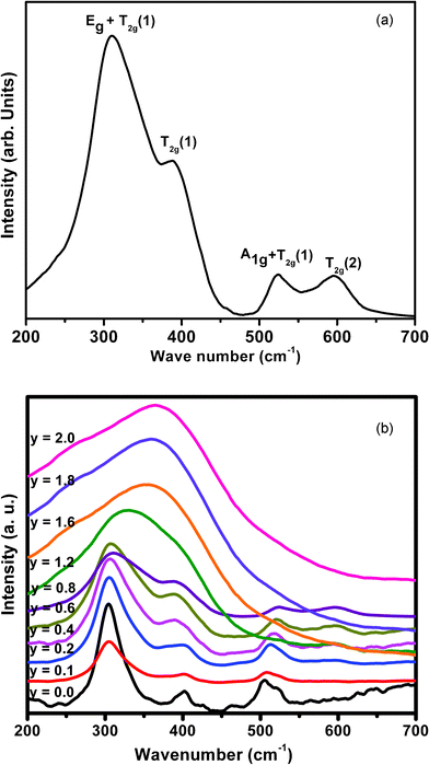 | ||
| Fig. 5 (a) Room temperature Raman spectrum of Nd1.2Ho0.8Zr2O7; (b) Room temperature Raman spectra of all compositions in the series Nd2−yHoyZr2O7 (0.0 ≤ y ≤ 2.0). | ||
From further observation of Fig. 5b, it is seen that the Raman spectra of all compositions beyond 40 mol% (y = 0.8) Ho3+ substitution, (i.e. from y = 1.2 to y = 2.0), consist of a broad hump centered around 350–400 cm−1. This clearly indicates the gross transformation of the ordered pyrochlore structure to a completely disordered defect fluorite structure beyond 40 mol% Ho3+ incorporation. It is known that the Raman spectrum of a fluorite structured oxide (A0.5B0.5O1.75) consists of only one Raman active mode (T2g) appearing in the form of a broad band, since all the O2− ions in this structure are randomly distributed over a total of eight available anion sites and hence are equivalent. This disorder in the anion sub-lattice results in the Raman spectrum being reduced to a broad continuum of density of states (DOS). These Raman spectroscopy results amply corroborate the conclusions drawn from the X-ray diffraction studies, as discussed earlier. A similar signature of phase transformation of an ordered pyrochlore to a disordered fluorite structure has been seen in one of our previous studies on the system Sm2−xDyxZr2O7 (0.0 ≤ x ≤ 2.0).33 A similar observation has been reported by Glerup et al.,28 where they observed a significant broadening of the Raman mode seen at around 531 cm−1 in Y2Ti2O7 upon Ti4+ being substituted by Zr4+, resulting in cation disorder in the lattice. They also reported an increase in broadening with increasing Zr4+ concentration. The corresponding mode in zirconates appears at around 520 cm−1 and a close look at the trend in Fig. 5b shows similar observation, where at around 60 mol% Ho3+ substitution (y = 1.2), the ∼520 cm−1 peak diminishes significantly, relative to other peaks. Considering that the broadening of the Raman lines is due to disorder or strain in the lattice, it clearly indicates that, upon Ho3+ substitution, the 48f oxygen atoms undergo significant disorder, while the 8b oxygen atoms are virtually undisturbed. Similar observations have been reported on MgO doped Nd2Zr2O7 and Nd2−xYxZr2O7 by Qu et al.34 and Mandal et al.,35 respectively. The variation in peak frequencies of different Raman modes as a function of increasing Ho3+ content is shown in Fig. 6. It is clear that the peak around 300 cm−1, corresponding to a combination of Eg and one of the T2g(1) modes (O–Nd(Ho)–O bending), shifts towards higher frequencies with increasing Ho3+ content, showing hardening of the corresponding bending mode. This is likely due to the smaller size of Ho3+ (1.015 Å) compared to Nd3+ (1.109 Å), which results in effective shortening of the O–Ho(Nd) distance, thereby increasing the energy required for the bending vibrations. A steep increase in the frequency, beyond 40 mol% Ho3+ content (y > 0.8), which actually corresponds to the single broad peak (T2g) observed in these compositions, is again corroborative evidence of the transformation from an ordered pyrochlore phase to a disordered fluorite phase at and beyond this composition. The inset of Fig. 6 represents stiffening of the Raman band around 520 cm−1 (corresponding to O–Zr–O bending and Nd(Ho)–O stretching) and softening of the band around 395 cm−1 (corresponding mainly to the Zr–O stretch) with increasing Ho3+ content. This can be attributed to an average effect of gradually increasing cation disordering in the system with increasing Ho3+ content.
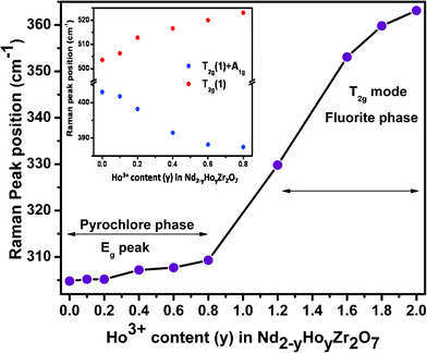 | ||
| Fig. 6 Variation of Raman peak positions with increasing Ho3+ content. The inset shows the variation in peak positions for the compositions stabilizing in the pyrochlore phase. | ||
In order to establish a correlation between the disorder induced into the system as a result of Ho3+ substitution and ionic conductivity, all the samples were subjected to ionic conductivity studies. Representative SEM images of the sintered samples used to correlate ionic conductivity measurements are shown in Fig. 7, and they reveal the dense microstructure with uniformly distributed small grains (average grain size ∼1–2 microns), separated by clean grain boundaries. Formation of such a dense and uniform microstructure can be attributed to the highly sinter active powder properties of these gel combustion synthesized solid solutions. A similar microstructure is observed for all the samples in the present series.
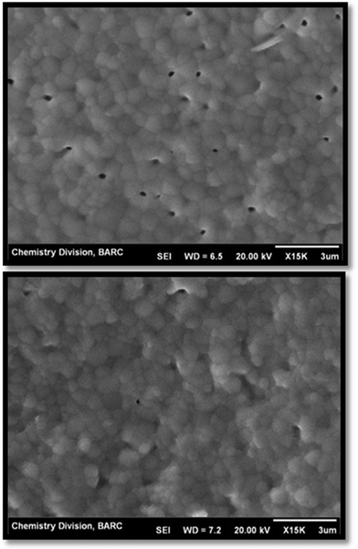 | ||
| Fig. 7 Microstructure of Nd0.8Ho1.2Zr2O7−δ sintered at 1723 K for 12 h. | ||
Nyquist plots of as-measured ac impedance (the imaginary part, ‘Z’(ω)', versus the real part, ‘Z’(ω)') for a few representative samples in the series Nd2−yHoyZr2O7 (y = 0.0, 0.6, 1.4 and 1.8), at different temperatures are shown in Fig. 8. One can observe different semicircular sections in all the plots, which are typical of the type usually found for polycrystalline ionic conductors. These sections, corresponding to the impedance associated with different regions in the samples, namely, bulk, grain-boundary and the sample–electrode interface region, were identified by the typical capacitance values associated with them.35 As seen from Fig. 8, for pure Nd2Zr2O7, the impedance is dominated by the bulk region with a small contribution from the grain boundaries. However, upon incremental substitution of Ho3+ for Nd3+ in the system, both bulk (grain interior) as well as grain boundary contributions become apparent. The incomplete semicircular arc at higher temperatures and lower frequencies can be assigned to the impedance associated with the sample–electrode interface (electrode polarization),36 since the ion-blocking effect becomes more prominent due to ions accumulating at the electrodes at higher temperatures.
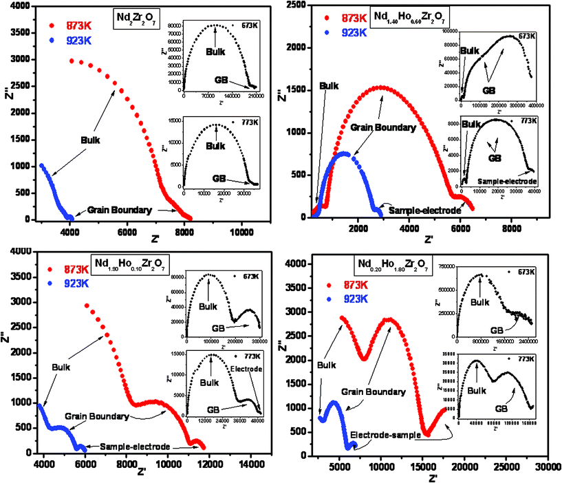 | ||
| Fig. 8 Nyquist plots for representative compositions, namely Nd2Zr2O7, Nd1.90Ho0.10Zr2O7, Nd1.40Ho0.60Zr2O7 and Nd0.20Ho1.80Zr2O7. | ||
The complex impedance plots were analyzed and fitted in equivalent circuits comprising a combination of resistive and capacitive (RC) elements arranged in parallel (one RC combination each for bulk, grain boundary and the electrode–sample interface region, as applicable) using Z view software. Using these fittings, the values of bulk resistance and grain boundary resistance were obtained, which were further used for calculation of bulk conductivity and grain boundary conductivity, respectively. Total conductivity of the samples was evaluated from the value of total resistance, taken from the real axis intercepts of the impedance plot (excluding the contribution from the sample–electrode interface region). Conductivity values were then evaluated using the cell constants (K = l/A) and resistance values (σ = 1/ρ = R/K = RA/l). The variation in total conductivity for all the samples in the form of the Arrhenius equation (i.e. ‘ln(σtotalT)’ vs. 1000/T) is shown in Fig. 9. Individual contributions to the conductivity, namely, bulk conductivity ‘ln(σbulkT)’ vs. 1000/T, and the grain boundary conductivity ‘ln(σgbT)’ vs. 1000/T, are also presented in the inset of the same figure. A linear relationship between ln(σtotalT) and 1000/T is obtained for all the solid solutions, indicative of the ionic nature of the conduction mechanism. Similar trends are seen for bulk conductivity (ln(σbulkT) vs. 1000/T) and grain boundary conductivity (ln(σgbT) vs. 1000/T) also. The activation energy of ionic conduction ‘Ea’ and the pre-exponential factor ‘σ0’, for total conductivity and bulk conductivity, as well as grain-boundary conductivity, were calculated from the slopes and intercepts of the linear fit of the corresponding Arrhenius plots, respectively. The results of these evaluations are shown in Fig. 10 a and b. Variation in conductivity (σtotal, σbulk and σgb) as a function of increasing Ho3+ concentration is also presented in Fig. 11.
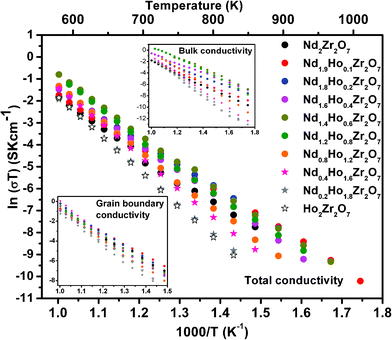 | ||
| Fig. 9 Arrhenius plots for Nd2−yHoyZr2O7 (0.0 ≤ y ≤ 2.0). | ||
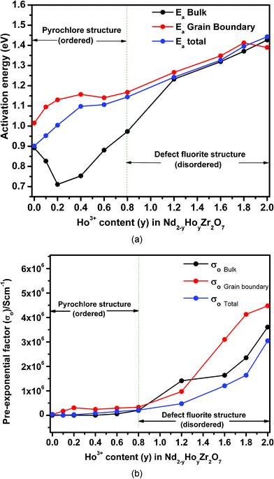 | ||
| Fig. 10 (a) Variation of activation energies for total conductivity, bulk conductivity and grain boundary conductivity as a function of Ho3+ concentration in Nd2−yHoyZr2O7; (b) variation of pre-exponential factor for total conductivity, bulk conductivity and grain boundary conductivity as a function of Ho3+ concentration in Nd2−yHoyZr2O7. | ||
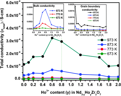 | ||
| Fig. 11 Variation of total conductivity as a function of Ho3+ concentration in Nd2−yHoyZr2O7. The insets show that, for both the bulk and the grain boundary cases, conductivity varies in a similar manner for a range of temperatures. | ||
From Fig. 10a, it is clear that the activation energy for the total conductivity (Ea-total) increases continuously with increasing Ho3+ concentration in the series Nd2−yHoyZr2O7. On the other hand, the trends of activation energy for individual contributions, namely bulk (Ea-bulk) and grain boundary conduction (Ea-GB) are somewhat different. The pre-exponential factors (σo-total, σo-bulk and σo-GB) show an increasing trend with increasing Ho3+ substitution. However, the increase is marginal in the composition range from pure Nd2Zr2O7 to Nd1.2Ho0.8Zr2O7 and significant thereafter from Nd1.2Ho0.8Zr2O7 to Ho2Zr2O7. Looking closely into the variation of activation energies for individual conduction mechanisms, it is seen that the activation energy for the bulk conduction ‘Ea-bulk’ initially decreases to 10 mol% Ho3+ (y = 0.2), increases rapidly up to 60 mol% Ho3+ (y = 1.2) and then increases almost linearly along with that for the total conductivity i.e. ‘Ea-total’. On the other hand, the activation energy for the grain boundary conduction ‘Ea-GB’ passes through a small incremental hump between pure Nd2Zr2O7 and 40 mol% Ho3+ (y = 0.4) and thereafter becomes nearly parallel to Ea-total. Fig. 11 shows that both the total ionic conductivity ‘σtotal’ and bulk conductivity ‘σbulk’ rise with increasing Ho3+ substitution, reach a maximum around 40 mol% Ho3+ (y = 0.8) and decrease thereafter with further incorporation of Ho3+. On the other hand, the grain boundary conductivity (σgb), which is higher than ‘σtotal’ or ‘σbulk’ throughout the composition range, does not show such a trend and remains nearly constant with increasing Ho3+ concentration. These results, obtained from analysis of impedance data, are explained below in light of the structural transformation from an ordered pyrochlore (Nd2−yHoyZr2O7, 0 ≤ y ≤ 0.8) to a disordered fluorite-type system (Nd2−yHoyZr2O7, 0.8 < y ≤ 2.0) observed in the present system.
Beginning with analysis of the bulk conductivity ‘σbulk’, the dominant mechanism of ionic charge transport in pure Nd2Zr2O7 grains, which is an ordered pyrochlore, is preferentially through hopping of oxide ions through orderly arranged vacant anion sites and thereby requires a smaller energy barrier to be overcome for oxide ion movement. The activation energy for this composition therefore should be the minimum, which indeed is observed in the variation of Ea-total as discussed earlier. On substituting some of the Nd3+ ions by Ho3+, partial disorder is introduced into the cation sub-lattice of the individual grains, whereas the anion sub-lattice on average remains nearly unperturbed (i.e. remains ordered, up to 40 mol% Ho3+, i.e. y = 0.80) in the pyrochlore structure. Such disorder in the cation sub-lattice of individual grains results in two mutually competing phenomena, namely, (a) increased hindrance towards oxide ion migration due to partial disorder, thereby leading to an increase in activation energy and (b) increased carrier concentration due to the disorder, resulting in a decrease in activation energy. The results shown in Fig. 10 and 11 indicate that the second factor dominates when Ho3+ is initially doped in Nd2Zr2O7 up to 10 mol% Ho3+ (y = 0.20), and a net drop in Ea-bulk along with an increase in conductivity (both σbulk and σtotal) is observed. However, for grain boundary conductivity in this region of Ho3+ incorporation (i.e. y = 0 to y = 0.2), opposing trends of increasing activation energy ‘Ea-GB’, and decreasing conductivity ‘σGB’ are observed. It must be noted that the grain boundary conductivity ‘σGB’, is nearly an order of magnitude higher compared to the bulk conductivity ‘σbulk’, or total conductivity ‘σtotal’, for pure Nd2Zr2O7 at 973 K and drops sharply with a small substitution of Nd3+ by Ho3+ (y = 0.10). Also, the value of Ea-GB is always higher than either Ea-bulk or Ea-total throughout the composition range, except for Ho2Zr2O7. As grain boundaries (comprising of grain surfaces) always have residual surface disorder in terms of incomplete/residual coordination, ionic transport through these boundaries will require relatively more energy compared to the grain interior and therefore Ea-GB is higher than Ea-bulk or Ea-total. Further, with increasing Ho3+ incorporation, additional disorder is possibly created on the grain surfaces due to Nd/Ho site mixing, thereby causing greater hindrance towards oxide ion migration and therefore a higher Ea-GB. A sharp drop in the grain boundary conductivity ‘σGB’, with nominal Ho3+ doping can also be attributed to higher resistance towards ion transport experienced through these regions compared to in the bulk regions.
With further substitution of Ho3+ for Nd3+ in Nd2−yHoyZr2O7 (between y = 0.2 to 0.8), where the pyrochlore structure is still retained by the system, a significant rise in bulk activation energy ‘Ea-bulk’, is seen along with an increasing trend in total conductivity ‘σtotal’, and bulk conductivity ‘σbulk’ finally reaching their maxima. However, grain boundary conductivity ‘σGB’, remains nearly steady. The rise in both Ea-bulk and Ea-total in this composition range is possibly due to dominance of the first factor, i.e. increased hindrance in the oxide ion migration through the lattice (increasingly disordered in the cation sub-lattice) over the effect of increasing carrier concentration. Conductivity increase (for both ‘σbulk’ and ‘σtotal’) in this region, on the other hand, is mainly due to increased carrier concentration due to Nd/Ho site mixing and preferential migration of oxide ions through an ordered array of vacant anion sites that are still present in the pyrochlore framework of these solid solutions. A nearly steady value of grain boundary conductivity ‘σGB’, in this region is perhaps an indication of uniform microstructure of the samples throughout the composition range.
Beyond the range of 40 mol% Ho3+ incorporation (i.e. between y = 0.8 and y = 2.0), the trends observed for activation energies and pre-exponential factors as well as conductivities are quite interesting. Whereas the activation energies (all including ‘Ea-total’, ‘Ea-bulk’ as well as ‘Ea-GB’) increase almost linearly, as well as being similar in magnitude, the conductivities (‘σbulk’ and ‘σtotal’) begin to fall with increasing Ho3+ concentration. Grain boundary conductivity ‘σGB’ however, still remains steady, similarly to that observed in the composition range y = 0.2 to 0.8. On the other hand, the pre-exponential factor, which is an indication of carrier concentration for ionic conductivity, increased significantly for all solid solutions in this region (i.e. 0.8 < y ≤ 2.0) compared to the region below y = 0.8, where only a nominal increase was noted. As already established from diffraction and Raman spectroscopy results, the solid solutions in this composition range crystallize in the defect fluorite structure, where the vacant anion sites are completely disordered, in contrast to the pyrochlore structure. Therefore, the compositions Nd2−yHoyZr2O7 (0.8 < y ≤ 2.0) have disorder prevailing in both the cation as well as in the anion sub-lattice, making the entire structure highly disordered. Such disorder thus results in the requirement of still higher energies for oxide ion migration, and therefore leads to higher activation energies (Ea-bulk, Ea-total and Ea-GB). It can also be seen that ‘Ea-bulk’, and ‘Ea-GB’ change nearly parallel to each other as well as ‘Ea-total’, in these highly disordered structures. The slightly higher value of ‘Ea-GB’, in this region is because of the additional surface-disorder present over the grain boundaries. Notably, the value of ‘Ea-GB’, for pure Ho2Zr2O7 is slightly lower than its nearby doped composition, mainly due to the absence of cation disorder in it.
Table 2 represents the total conductivity at 873 K with change in activation energy and the pre-exponential factor with increasing Ho3+ substitution. The pre-exponential factor, which shows a significant increase in the region (0.8 < y ≤ 2.0), again confirms the increasing extent of disorder in the structure arising due to (i) disorder in the anion sub-lattice of the defect fluorite structure and (ii) increasing disorder in the cation sub-lattice due to Nd/Ho site mixing. Finally the declining trend of conductivity (‘σbulk’ and ‘σtotal’), beyond 40 mol% Ho3+ can be explained as being due to the higher degree of disorder prevalent in both the cation and anion sub-lattice of these fluorite-type solid solutions, resulting in the absence of the preferred diffusion paths for the oxide ions through ordered anion vacancies, which otherwise were present in the pyrochlore lattice (0.0 ≤ y ≤ 0.8) and therefore decrease the conductivity. The average accuracy of the conductivity values reported herein is about ±3%, as obtained from similar measurements on a standard YSZ sample (8 at.% Y2O3 doped ZrO2) and compared with recommended values.
| Sample | Activation energy (Ea-total) eV | Pre-exponential factor (σ0) S cm−1 | Regression coefficients | Conductivity at 873 K (σtotal) S cm−1 |
|---|---|---|---|---|
| y = 0.0 | 0.901 | 3.48 × 10⁴ | −0.9976 | 2.9 × 10⁻⁵ |
| y = 0.1 | 0.952 | 1.02 × 10⁴ | −0.9994 | 3.6 × 10⁻⁵ |
| y = 0.2 | 1.004 | 2.64 × 10⁴ | −0.9998 | 4.8 × 10⁻⁵ |
| y = 0.4 | 1.097 | 8.31 × 10⁴ | −0.9998 | 4.4 × 10⁻⁵ |
| y = 0.6 | 1.106 | 15.43 × 10⁴ | −0.9993 | 7.5 × 10⁻⁵ |
| y = 0.8 | 1.144 | 21.26 × 10⁴ | −0.9987 | 6.1 × 10⁻⁵ |
| y = 1.2 | 1.242 | 47.48 × 10⁴ | −0.9995 | 3.6 × 10⁻⁵ |
| y = 1.6 | 1.326 | 120.44 × 10⁴ | −0.9998 | 3.0 × 10⁻⁵ |
| y = 1.8 | 1.395 | 304.72 × 10⁴ | −0.9998 | 1.7 × 10⁻⁵ |
| y = 2.0 | 1.442 | 163.91 × 10⁴ | −0.9999 | 1.6 × 10⁻⁵ |
From analysis of the XRD and conductivity data, it can be suggested that the variations in conductivity as well as activation energy depend on the values of the x-parameter, which are the characteristic features of the pyrochlore lattice, and also on the anion occupation in the pyrochlore lattice. As mentioned earlier, the increasing trend of x-parameters indicates a tendency to transform pyrochlore-type ordering into fluorite-type ordering. However, the ideal value of the fluorite lattice has not been achieved, even up to the maximum limit of substitution of the present system. Thus, the presence of anion vacancies in the pyrochlore lattice may have a predominant role in the increasing trend of total conductivity. In the present study it is also observed that the 8b sites, which are vacant in an ideal pyrochlore, have an appreciable (∼20%) oxygen occupation. Thus, significant numbers of anion vacancies in the 8a and 8b sites in all the studied compositions are observed. Also, the distribution of anions in the 8a and 8b sites shows an increasing trend with increasing Ho3+, which favors the ionic conduction. Such behavior of easier percolation of oxygen has been reported in several cases of defect pyrochlores compared to the corresponding ideal systems. The higher degree of disorder in the anion sites may also show a resistive behavior to the migration of anions, compared to the ordered array where an easy passage for migration or short hopping is favored. Such variation in the fractional occupations of the different anion sites could also be a reason for the non linear variation of the activation energies. In a pyrochlore lattice, the anion migration can be easily understood from the migration of an anion from occupied tetrahedral to empty octahedral (or trigonal) as well as from tetrahedral to partially occupied tetrahedral sites. However, the presence of vacancies in the tetrahedral sites can cause easy short range hopping around a site. Besides, a decreasing trend in the unit cell parameters suggests a decreasing trend in the distance of occupied and unoccupied sites to favor anion migration, at the same time narrowing the channel size to counter this. In the initial region, the increase in conductivity and decrease in the activation energy can be related to this short range hopping amplitude, due to relatively lower vacancies and larger free space in the lattice compared with higher Ho3+ content.
These results have therefore established the strong correlation between structural transformation and the ionic transport mechanism, which will have direct relevance for practical applications of such ionic conductors. It is also clear that composition with 40 mol% Ho3+ shows the highest ionic conductivity in this system. It therefore opens up an opportunity to tune the compositions around these compositions by incorporation of suitable additives, so as to further improve upon the conductivity of these pyrochlores for their potential applications.
4. Conclusion
The complete series of solid solutions Nd2−yHoyZr2O7 (0.0 ≤ y ≤ 2.0) has been successfully prepared by the gel combustion route, followed by sintering. Detailed structural characterization using X-ray diffraction and Raman spectroscopy techniques has revealed that the system undergoes a structural transformation from an ordered pyrochlore phase (Nd2−yHoyZr2O7, 0.0 ≤ y ≤ 0.8) to a disordered defect fluorite-type phase (Nd2−yHoyZr2O7, 0.8 ≤ y ≤ 2.0). Ionic conductivity studies have revealed an optimum composition of Nd1.2Ho0.8Zr2O7 to show maximum conduction in the series. A correlation has been successfully established between the ionic conductivity and the structural transformation, delineating the effect of the transition from an ordered phase to a disordered one in different ion conduction mechanisms.Acknowledgements
The authors are thankful to Dr S. N. Achary, BARC, for fruitful discussion. The Department of Atomic Energy's Science Research Council is acknowledged for supporting this work via sanction number 2010/21/9-BRNS/2025.References
- M. Deepa, R. P. Prabhakar, A. N. Radhakrishnan, K. S. Sibi and P. Koshy, Mater. Res. Bull., 2009, 44, 1481–1488 CrossRef CAS.
- K. S. Sibi, A. N. Radhakrishnan, M. Deepa, R. P. Prabhakar and P. Koshy, Solid State Ionics, 2009, 180, 1164–1172 CrossRef CAS.
- J. A. Díaz-Guillén, A. F. Fuentes, M. R. Díaz-Guillén, J. M. Almanza, J. Santamaría and C. J. León, J. Power Sources, 2009, 186, 349–352 CrossRef.
- G. T. Knoke, A. Niazi, J. M. Hill and D. C. Johnston, Phys. Rev. B: Condens. Matter Mater. Phys., 2007, 76, 054439 CrossRef.
- M. Hirayama, N. Sonoyama, A. Yamada and R. Kanno, J. Lumin., 2008, 128, 1819–1825 CrossRef CAS.
- A. Zhang, M. Lü, Z. Yang, G. Zhou and Y. Zhou, Solid State Sci., 2008, 10, 74–81 CrossRef CAS.
- R. C. Ewing, Proc. Natl. Acad. Sci. U. S. A., 1999, 96, 3432–3439 CrossRef CAS.
- R. C. Ewing, W. J. Weber and J. Lian, J. Appl. Phys., 2004, 95, 5949–5971 CrossRef CAS.
- R. N. Basu, Recent Trends in Fuel Cell Science and Technology, 2007, 286–331 CrossRef.
- R.V. Kumar, H. Iwahara and J. A. L. E. K. A. Gschneidnerin, Handbook on the Physics and Chemistry of Rare Earths, Elsevier 2000, ch. 28, pp. 131–185 Search PubMed.
- P. K. Moon and H. L. Tuller, Sens. Actuators, B, 1990, 1, 199–202 CrossRef.
- M. A. Subramanian, G. Aravamudan and G. V. S. Rao, Prog. Solid State Chem., 1983, 15, 55–143 CrossRef CAS.
- J. Wang, A. Nakamura and M. Takeda, Solid State Ionics, 2003, 164, 185–190 CrossRef CAS.
- C. Wan, Z. Qu, A. Du and W. Pan, J. Am. Ceram. Soc., 2011, 94, 592–596 CrossRef CAS.
- F. X. Zhang, B. Manoun and S. K. Saxena, Mater. Lett., 2006, 60, 2773–2776 CrossRef CAS.
- J. Lian, W. J. Weber, W. Jiang, L. M. Wang, L. A. Boatner and R. C. Ewing, Nucl. Instrum. Methods Phys. Res., Sect. B, 2006, 250, 128–136 CrossRef CAS.
- J. Lian, L. Wang, J. Chen, K. Sun, R. C. Ewing, J. M. Farmera and L. A. Boatner, Acta Mater., 2003, 51, 1493–1502 CrossRef CAS.
- M. R. Díaz-Guillén, K. J. Moreno, J. A. Díaz-Guillén, A. F. Fuentes, J. García-Barriocanal, J. Santamaría and C. León, Defect Diffus. Forum, 2009, 289, 347–354 CrossRef.
- S. Murugesan, N. H. Muhammad, Y. Yanfa, M. A. Mowafak and V. (Ravi) Subramanian, J. Phys. Chem. C, 2010, 114, 10598–10605 CAS.
- I. Riess, D. Braunshtein and D. S. Tannhauser, J. Am. Ceram. Soc., 1981, 64, 476–479 CrossRef.
- L. R. Pederson, L. A. Chick and G. J. Exarhos,U.S. Patent No. 5 114 702, 1992.
- J. Rodriguez-Caravajal, Fullprof: A program for Rietveld refinement and pattern matching, Abstract of the Satellite Meeting on Powder Diffraction, 15th Congress of the IUCr, Toulouse, France, 1990, p. 127 Search PubMed.
- C. Heremans, B. J. Wuensch, J. K. Stalick and E. Prince, J. Solid State Chem., 1995, 117, 108–121 CrossRef CAS.
- S. J. Dickson, K. D. Hawkings and T. J. White, J. Solid State Chem., 1986, 82, 146–150 CrossRef.
- B. C. Chakoumakos, Pyrochlore, McGraw-Hill Yearbook of Science & Technology 1987, ed. S. P. Parker, McGraw-Hill, Inc., New York, 1986, pp. 393–395 Search PubMed.
- R. D. Shannon, Acta Crystallogr., Sect. A: Cryst. Phys., Diffr., Theor. Gen. Crystallogr., 1976, 32, 751–767 CrossRef.
- B. J. Wuensch, K. W. Eberman, C. Heremans, M. K. Esther, P. Onnerud, E. M. E. Yeo, S. M. Haile, J. K. Stalick and J. D. Jorgensen, Solid State Ionics, 2000, 129, 111–133 CrossRef CAS.
- M. Glerup, O. F. Nielsen and F. W. Poulsen, J. Solid State Chem., 2001, 160, 25–32 CrossRef CAS.
- R. A. McCauley, J. Appl. Phys., 1980, 51, 290–294 CrossRef CAS.
- D. L. Rousseau, R. P. Bauman and S. P. S. Porto, J. Raman Spectrosc., 1981, 10, 253–290 CrossRef CAS.
- F. X. Zhang, B. Manoun, S. K. Saxena and C. S. Zha, Appl. Phys. Lett., 2005, 86, 181906 CrossRef.
- (a) B. E. Scheetz and W. B. White, J. Am. Ceram. Soc., 1979, 62, 468 CrossRef CAS; (b) D. Michel, M. J. Perez and R. Collongues, Mater. Res. Bull., 1974, 9, 1457–1468 CrossRef CAS.
- F. N. Sayed, V. Grover, K. Bhattacharyya, D. Jain, C. G. S. Pillai, A. Arya and A. K. Tyagi, Inorg. Chem., 2011, 50, 2354–2365 CrossRef CAS.
- Z. Qu, C. Wan and W. Pan, Chem. Mater., 2007, 19, 4913–4918 CrossRef CAS.
- B. P. Mandal, A. Dutta, S. K. Deshpande, R. N. Basu and A. K. Tyagi, J. Mater. Res., 2009, 24, 2855–2862 CrossRef CAS.
- J. T. S. Irvine, D. C. Sinclair and A. R. West, Adv. Mater., 1990, 2, 132–138 CrossRef CAS.
| This journal is © The Royal Society of Chemistry 2012 |