DOI:
10.1039/C2RA20674A
(Paper)
RSC Adv., 2012,
2, 8352-8358
An environmentally friendly method for the synthesis of nano-alumina with controllable morphologies
Received
12th April 2012
, Accepted 5th July 2012
First published on 6th July 2012
Abstract
The relatively high price of aluminum alkoxides as an alumina source and organic surfactants as morphology control or structure directing agents are less attractive for practical applications to the synthesis of nanostructured alumina. Moreover, some of these synthesis processes may generate large masses of salt by-products. A highly efficient synthesis of nano-alumina from ammonium carbonate aqueous solution and aluminum nitrate ethanol solution without the use of a template and complicated processes has been achieved. The Al(NO3)3·9H2O reagent can be completely converted to nano-alumina without a by-product and the ethanol solutions can be reused. In addition, the CO2 and NH3 produced can also be recycled to the reagent (NH4)2CO3. The nano-alumina synthesized is of γ-alumina structure. Moreover, the simple and environmentally friendly route described could enhance the synthesis technology for nano-alumina and its applications.
1. Introduction
Alumina has been widely used as an adsorbent, ceramic, heat insulating material, membrane, catalyst and catalyst support due to its unique physical and chemical characteristics.1–6 The properties of alumina are determined predominantly by the crystal phase, composition, pore structure and morphology. Thus, the performance of alumina in its applications as an adsorbent, catalyst and catalyst support could be optimized by adjusting the surface area, pore structure and morphology.7–11 As a result, the synthesis of nanostructured alumina with controllable textural structure and morphology has attracted great attention in recent years.
The synthesis of nanocrystalline alumina with controlled morphologies such as belts,12,13 tubes,14 sheets,15 wires,16,17 rods,18–20 whiskers 5 and fibers21 have been reported. Nano-alumina can be prepared using thermal evaporation methods,22 chemical etching,23 sol–gel methods,24 continuous anodizing,25 decomposition of nano-metric ammonium aluminum carbonate hydroxide (AACH) 26 and hydrothermal synthesis.19 Zhang et al.27 reported a three-step assembly pathway to prepare porous lathe- and rod-shaped alumina nanoparticles using a nonionic surfactant. Zhu et al.28 prepared γ-alumina nano-fibers with large pore volumes (1.10∼1.90 cm3 g−1) from aluminum hydrate using poly (ethylene oxide) as surfactants. Lee et al.14 reported the synthesis of hollow alumina nanotubes using surfactants without organic solvent. Recently, Chowdhury et al.29 reported the synthesis of high surface area alumina nano-fibers in supercritical carbon dioxide using aluminum isopropoxide. Suchanek et al.30,31 reported the synthesis of α-Al2O3 nano-materials at 703–723 K under a 10.3 MPa pressure by the hydrothermal treatment of boehmite powder (γ-AlOOH) in the presence of α-Al2O3 seeds and 1–10% morphology modifiers. Notwithstanding, the decomposition of AACH is a promising method to produce ultra pure and sinterable α-Al2O3 powders. Sun et al.32 fabricated nanocrystalline α-Al2O3 powders by the decomposition of AACH, which was synthesized by adding ammonium aluminum sulfate (AAS) solution to ammonium bicarbonate (AHC) solution with poly (ethylene glycol) as the surfactant. Every one of the many methods proposed for the synthesis of nanocrystalline alumina has its own disadvantage. For instance, the relatively high price of aluminum alkoxides as the alumina source and organic surfactants as the structure directing agents are less attractive for practical applications. For some other methods, long reaction times, severe reaction conditions, the use of special instruments, complicated procedures and relatively high temperatures makes them costly and inconvenient. Thus, it is still a challenge to design a simple, low cost and environmentally friendly method for the preparation of ultra pure alumina with controllable morphology.
Ammonium carbonate ((NH4)2CO3) and aluminum nitrate are chemical reagents that are inexpensive, easily available and widely used in the chemical industry. In this report, ethanolic aluminum nitrate and aqueous ammonium carbonate solutions were used to prepare γ-alumina nanoparticles, nanorods and nano-fiber precursors by controlling only the initial pH of the final solution and the manner of the addition of the (NH4)2CO3 solution at 353 K under atmospheric pressure. The Al(NO3)3·9H2O reagent can be converted to nano-alumina without generating worthless salt by-products and the ethanol solution is reusable after separation, minimizing waste. The CO2 and NH3 produced can also be recycled by absorbing them in NH3·H2O to produce (NH4)2CO3 reagent, which could reduce the cost. Thus, the method described provides an environmentally friendly route for the synthesis of nano-alumina from inexpensive sources. This mechanism will also be discussed.
2. Experimental
2.1 Material synthesis
Reagent grade aluminum nitrate (Al(NO3)3·9H2O), ammonium carbonate ((NH4)2CO3), anhydrous ethanol (Sinopharm Chemical Reagent Co., Ltd., China) and deionized water were used as the starting chemicals without further purification. In a typical experiment, 5 g of Al(NO3)3·9H2O was dissolved in 100 ml of anhydrous ethanol under continuous stirring and the solution was heated to 353 K. Aqueous ammonium carbonate solution (1 mol L−1) was then added drop-wise to prepare the sol until the pH reached 7.5, 8.0, 8.5, 9.0 and 9.5, respectively. The sol was continuously stirred for 2 h and aged at 353 K for 24 h. The products were then separated from the solution by filtration and washed with deionized water and anhydrous ethanol several times. The obtained white precipitates were dried at 383 K for 12 h in air, heated to 873 K from room temperature with a heating rate of 2 K min−1 and kept at 873 K for 5 h to obtain the nanostructured γ-alumina product.
The effect of anhydrous ethanol and the effect of the addition pattern of the ammonium carbonate aqueous solution on the morphology of the products was further investigated.
2.2 Characterization
X-ray diffraction studies of the prepared sample were carried out with a Bruker advanced-D8 powder diffractometer, using Cu-Kα radiation (λ = 1.5456 Å) operated at 40 kV and 40 mA and with a Vanter-1 detector. Transmission electron microscopy (TEM) images were obtained using an FEI Tecnai G2-20 instrument. The powder samples were directly suspended in ethanol with ultrasonic treatment and dropped onto a copper grid for observation. A nitrogen adsorption–desorption measurement was conducted at 77 K, with a Quantachrome Autosorb-1-C-MS instrument. Prior to the measurement, the sample was outgassed at 473 K for 6 h. The surface area was obtained using the Brunauer–Emmet–Teller (BET) model, for the adsorption branch in a relative pressure (P/P0) range of 0.05 to 0.30. Pore volumes were calculated from the adsorption data at a relative pressure of 0.995. Pore size distributions were evaluated from the desorption branch using the Barret–Joyner–Halenda (BJH) method. Fourier transform infrared (FT-IR) spectra of the samples were collected using a Nicolet Fourier transform infrared spectrometer (NEXUS 470). For the analyses, the powder samples were mixed with potassium bromide (KBr) powder and pressed into disks.
3. Results and discussion
3.1 Effect of initial pH on phase transformation of the products
Fig. 1 shows the X-ray powder diffraction patterns of the products prepared at different initial pH values and dried at 383 K, for 12 h. A pseudo-boehmite (PB) phase (JCPDS-ICDD: 83-2384) 33 was formed in a sample prepared at pH 7.5 (Fig. 1 curve a). The weak and broad peak intensity suggested the sample has a small particle size. PB is a well studied aluminum hydroxide having the general formula of AlOOH·nH2O. It exhibits similar diffraction peak positions as boehmite but has a smaller particle size and more crystal defects.33 Both the pseudo-boehmite and ammonium aluminum carbonate hydroxide (AACH) phases (JCPDS-ICDD: 42-0250) 34 appeared in the samples prepared at an initial pH of 8.0 (Fig. 1 curve b), 8.5 (Fig. 1 curve c) and 9.0 (Fig. 1 curve d). The strong peak intensity of the samples synthesized at an initial pH of 9.5 (Fig. 1 curve e), indicates that the AACH phase is highly crystalline. The changes observed in the XRD patterns showed that the initial pH value of the solution is important in the formation of products with different crystalline phases.
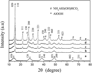 |
| | Fig. 1 XRD patterns of the products prepared at initial pH values of (a) 7.5, (b) 8.0, (c) 8.5, (d) 9.0 and (e) 9.5, and dried at 383 k for 12 h. | |
Fig. 2 shows the FTIR spectra of the dried samples obtained from different pH values. The broad absorption peaks at 3400–3700 cm−1 are due to the O–H stretching of chemisorbed water. The bands at 1390, 1720, 1837, 2845, 3026, 3102 and 3180 cm−1 are attributed to the NH4+ groups and those observed at 739–756, 856, 1100, 1450 and 1546 cm−1 are attributed to CO3− anion species.35–39 The characteristic Al–O vibration appears at 450–700 cm−1 and the sharp bands at 987 cm−1 in AACH and 1080 cm−1 in PB are assigned to Al–OH vibration.35–38 The FTIR results are consistent with the results of the XRD patterns; the synthesized products existed in the PB, AACH and PB–AACH structures.
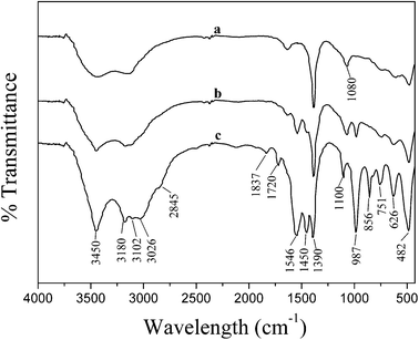 |
| | Fig. 2 FT-IR spectra of the products obtained at initial pH values of (a) 7.5, (b) 8.5 and (c) 9.5, and dried at 383 K for 12 h. | |
3.2 Thermal transformation of the precursor to γ-Al2O3
The PB (pH 7.5), PB–AACH (pH 8.5) and AACH (pH 9.5) phases in the dried products were converted to the γ-Al2O3 phase (JCPDS: 47-1308) after calcination in static air at 873 K for 5 h (see Fig. 3). A slight increase in the intensities of the XRD peaks at 2θ = 66.7°, 45.8° and 37.5° is observed with the increase of the initial pH values. Nevertheless, all of them showed broad diffraction peaks, indicating the formation of small particles after calcination. This may be attributed to the decomposition of the AACH precursor (to γ-Al2O3), from which CO2, NH3 and H2O were released, suppressing the crystal growth and aggregation and leading to an increase in the distance between the alumina particles. This is consistent with the observation of Stoica et al.35 that AACH-derived oxides were resistant to sintering into large γ-alumina crystals when calcined at temperatures of 523–1073 K.
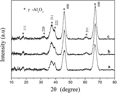 |
| | Fig. 3 XRD patterns of the products prepared at initial pH values of (a) 7.5, (b) 8.5 and (c) 9.5, subsequently dried at 383 K for 12 h and calcined at 873 K for 5 h. | |
3.3 Morphology of the prepared samples
Fig. 4 shows the TEM images of the synthesized products dried at 383 K for 12 h (left images) and those subsequently calcined at 873 K for 5 h (right images). The morphology of the dried samples is significantly affected by the initial pH value of the solution. Curved nano-fibers with diameters of 4–6 nm and lengths of 80–300 nm were obtained in the dried product, prepared at an initial pH of 7.5 (Fig. 4a). The calcined γ-Al2O3 nano-fibers (Fig. 4b) are, however, slightly thinner than the dried PB nano-fibers. A mixture of nano-lathes and nano-fibers of PB–AACH was observed for the dried samples prepared at an initial pH of 8.5 (Fig. 4c). The lengths of the nano-lathes are 50–200 nm and the widths are 30–40 nm. The γ-Al2O3 (Fig. 4d) obtained from calcination of the PB–AACH nano-hybrids is a mixture of nanorods and nanoparticles. From the results shown in Fig. 4b and Fig. 4f, it can be inferred that the nanorods resulted from the PB crystalline nanostructure phase and the nano-lathes resulted from the AACH crystalline phase. Indeed, the TEM image of the AACH prepared at pH 9.5 and dried at 383 K for 12 h (see Fig. 4e) showed that the product obtained has lathe-like and porous nanostructures. The formation of porous structures could be due to the release of physically adsorbed water and ethanol in the internal structures of the AACH crystals. Fig. 4f shows that the γ-Al2O3 transformed from pure AACH has interconnected pore structures between the nanoparticles with average diameters of 6–8 nm due to the release of CO2, NH3 and H2O gases during the decomposition of AACH.38
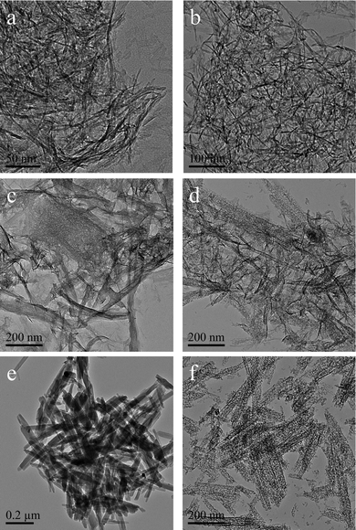 |
| | Fig. 4 TEM images of the products prepared at initial pH values of 7.5, 8.5 and 9.5 dried at 383 K for 12 h (a, c, e), and those subsequently calcined at 873 K for 5 h (b, d, f). | |
3.4 Textural properties of the prepared γ-Al2O3
Fig. 5 shows the N2 adsorption–desorption isotherms and the pore-size distribution (inset) of the nanostructured γ-Al2O3 obtained from different precursors. All the isotherms have a type IV shape with H3 and H4 hysteresis loops. The various pore distributions are attributed to different pore formation mechanisms. The γ-Al2O3 nano-fibers resulting from PB (Fig. 5 curve a) have H4 loops, owing to the irregular and broad size distribution. This is in agreement with the TEM images, which show that the interconnected pore structure consists of the hierarchical ordering of γ-Al2O3 nano-fibers in a disorderly arrangement. For the γ-Al2O3 prepared from PB–AACH (Fig. 5 curve b) and AACH (Fig. 5 curve c), there are two hysteresis loops in the isotherms and a similar hierarchical pore distribution. The smaller pores, which are presumably decomposed from AACH, are in the range of 6–7 nm and the larger ones, which presumably arose from nanoparticles and nano-fibers assembled in the lathe-like structure, are broadly distributed in the range of 30–60 nm.
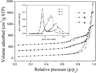 |
| | Fig. 5 N2 adsorption–desorption isotherms and pore size distributions of products obtained at initial pH values of (a) 7.5, (b) 8.5 and (c) 9.5, and subsequently dried at 383 K for 12 h and calcined at 873 K for 5 h. | |
The BET specific surface areas, pore volumes and pore diameters of the γ-Al2O3 samples are shown in Table 1. Compared with conventional alumina that show surface areas of below 250 m2 g−1 and pore volumes below 0.50 cm3 g−1,27 the alumina synthesized in our work possesses a higher surface area (260–290 m2 g−1) and larger pore volume (1.80–2.40 cm3 g−1). The higher specific surface area, interconnected pore structure and large pore volume were formed in the aggregation of the randomly oriented nano-fibers and nanoparticles. These characteristics could ensure that the reactant flows through the material bed, easily minimizing the problem of diffusion difficulties that could seriously affect the adsorption and catalysis process.40
Table 1 Textural properties of the products obtained at different initial pH values, subsequently dried at 383 K for 12 h and calcined at 873 K for 5 h and 1273 K for 2 h
| Preparation pH and calcination temperature (K) |
BET surface area (m2 g−1) |
Pore diameter (nm) |
Pore volume (cm3 g−1) |
| 7.5/873 |
260.8 |
20.6 |
1.80 |
| 8.5/873 |
276.6 |
6.9,39.7 |
2.08 |
| 9.5/873 |
290.0 |
7.3,49.5 |
2.41 |
| 7.5/1273 |
171.4 |
25.0 |
1.49 |
| 8.5/1273 |
146.7 |
38.6 |
1.60 |
| 9.5/1273 |
138.7 |
14.3,63.6 |
1.76 |
3.5 Thermal stability of the prepared γ-Al2O3 nanostructure
The thermal stability is also an important characteristic of the prepared γ-Al2O3 for its application. To compare the thermal stability of the synthesized nano-fibers, nanoparticles and their hybrids, the γ-Al2O3 samples were further calcined at 1273 K for 2 h. The morphology of the nano-fibers (Fig. 6 picture a) is similar to the γ-Al2O3 precursor. The diameter is about 6–8 nm and the length is about 50–200 nm. The nanoparticles (Fig. 6 picture c) were larger than the γ-Al2O3 precursor, with diameters of about 6–10 nm, and aggregated from sintering after calcination at 1273 K for 2 h. The XRD analysis of the calcined samples (Fig. 6) shows that alumina nano-fibers still had a crystalline phase of γ-Al2O3. The nanoparticles were transformed to the hybrid phases of γ-Al2O3 and θ-Al2O3 (JCPDS-ICDD: 35-0121). The XRD peaks and TEM images of the samples show that the nanoparticle sample calcined at this temperature have a high crystallinity and increases in grain sizes were more significant than those in the nano-fibers. After heat treatment at 1273 K for 2 h, as shown in Table 1, the nanoparticles have a specific surface area of 138.7 m2 g−1, which is slightly lower than that reported by Giannos et al.41 (145 m2 g−1 at 1273 K for 2 h). However, the nano-fibers still retain a higher BET surface area of 171 m2 g−1 and a larger pore volume of 1.49 cm3 g−1. These show that the alumina nano-fibers possess the important sintering stability for their application as a high temperature catalyst. The reason for the decrease of the BET surface area and pore volume was due to micropore collapse, phase changes and the stacking of nanoparticles, which reduced the intercrystalline space and agglomeration.29 The effect of calcination on the morphology and structure of the samples indicates that the sintering of alumina nano-fibers with small contact areas is lower than that of nanoparticles.
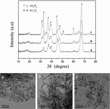 |
| | Fig. 6 XRD patterns and TEM images of the products prepared at initial pH values of (a) 7.5, (b) 8.5 and (c) 9.5, subsequently dried at 383 K for 12 h and calcined at 873 K for 5 h and 1273 K for 2 h. | |
3.6 Effect of ethanol on the synthesis of boehmite nano-fibers
To further understand the mechanism of the formation of boehmite nano-fibers, the experiment using water instead of ethanol in aluminum nitrate solution was carried out at pH 7.5. The TEM images and XRD patterns in Fig. 7 (picture a and curve a), show that the aggregated aluminum hydrate was formed in the absence of ethanol and after calcination it was transformed to agglomerated γ-Al2O3 (TEM images and XRD patterns in Fig. 7 picture b and curve b). The fast hydrolysis of the aluminum precursors in aqueous media usually causes the formation of lamellar hydrated hydroxides.42 Chowdhury et al.29 reported the synthesis of alumina nano-fibers from aluminum isopropoxide in supercritical CO2. They suggested that the controlled hydrolysis in supercritical CO2 by the low solubility of water (∼0.1 wt%), decreases the sol–gel reaction rate and facilitates the formation of a well-defined nanostructure. Teoh et al.24 prepared alumina nano-fibers in a binary water-alcohol solvent system using aluminium isopropoxide with the sol–gel method. They suggested that the dominant factor governing the formation of nano-fibers is the degree of hydrolysis and condensation. This experiment using water instead of ethanol in aluminum nitrate solution shows that aggregated aluminum hydrated and formed in the absence of ethanol. This indicates that the low solubility of ammonium carbonate in ethanol retarded the rate of hydrolysis and condensation of the aluminum precursors in an ethanol–water solution, thus facilitating the formation of a well-defined nanostructure instead of precipitation, similar to previous reports.29
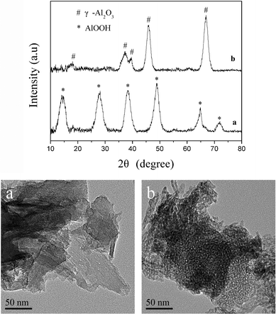 |
| | Fig. 7 XRD patterns and TEM images of products obtained from aqueous aluminum nitrate solution at pH 7.5 after (a) being dried at 383 K for 12 h and (b) being calcined at 873 K for 5 h. | |
3.7 Effect of the input rate on the synthesis of AACH nano-lathes
An additional experiment was carried out to study the effect of varying the rate of the addition of ammonium carbonate solution into ethanolic aluminum nitrate with a prepared AACH. When ammonium carbonate solution was added at once and the final pH value controlled at 9.5, the TEM (Fig. 8 picture a) and XRD (Fig. 8 curve a) results show that narrower and shorter AACH nano-lathes were obtained compared with AACH formed from the drop-wise addition (Fig. 4 picture e). Furthermore, calcination of these AACH nano-lathes leads to the formation of γ-Al2O3 nanorods (TEM image in Fig. 8 picture b and XRD patterns in Fig. 8 curve b), with diameters of 6–8 nm and lengths of 20–50 nm, while calcination of the nano-lathes by drop-wise addition leads to the formation of a particular particle material, as shown in Fig. 4f. Compared with the drop-wise addition, rapid mixing of ammonium carbonate aqueous solution with aluminum nitrate ethanol solution leads to the rapid increase of concentrations of HCO3+ and NH4+ ions. Moreover, the aluminum precursor formed more AACH crystal precursors, which grew into uniform and small AACH nano-lathes. This additional experiment indicated that the formation and morphology of AACH was affected significantly by the concentration of HCO3+ and NH4+ ions in the solution.
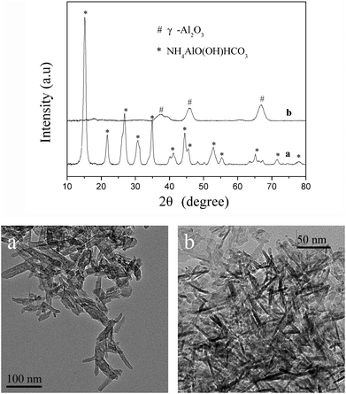 |
| | Fig. 8 XRD patterns and TEM images of the products obtained when ammonium carbonate aqueous solution was added at once and pH 9.5 after (a) being dried at 383 K for 12 h and (b) being calcined at 873 K for 5 h. | |
3.8 Discussion
As demonstrated by XRD in Fig. 1 and the TEM images in Fig. 4, the initial pH value of the ethanol–water solution greatly affects the phase and morphology of the products synthesized. In the experimental process, it was found that when the solution pH value was first set at 5–6 it swelled the amorphous sol and bubbles were observed at the initial stage of the reaction. It was presumed that water intercalation took place in the presence of excess water, resulting in swelling of the layered structure of boehmite, to form swelling of the amorphous sol.43 The moderated condensation rate of the amorphous boehmite precursors in ethanol–water inhibit random particle aggregation, leading to growth in specific crystallographic directions by hydrogen bonds. The addition of ammonium carbonate leads to an increase of HCO3− and NH4+ ion concentrations, which interact variously with amorphous boehmite precursors. These steps are outlined below:| | | 2Al(NO3)3 + 3(NH4)2CO3 + H2O = 2AlOOH↓ + 6NH4NO3 + 3CO2↑ | (1) |
| | | (NH4)2 CO3 + H2O = 2NH4+ + HCO3− + OH− | (2) |
| | | AlOOH + HCO3− + NH4+ = NH4AlO(OH)HCO3↓ | (3) |
With excess (NH4)2CO3| | | Al(NO3)3 + 2 (NH4)2CO3 + H2O = NH4AlO(OH)HCO3↓ + 3 NH4NO3 + CO2↑ | (4) |
In our reaction system, AACH formation is attributed to the reaction of the amorphous boehmite phase with excess NH4+ and HCO3− through Eqn. (3). This is consistent with the previous report.44 The morphology of AACH is shown in Fig. 4e and Fig. 8a. AACH formed nano-lathe structures under two different experimental conditions. This result might be due to the faster growth of AACH crystals along a particular crystal face. AACH with acicular geometry has also been observed.36,45,46 Our experimental results probably indicate that AACH is thermodynamically and kinetically more favored for acicular crystals.47
4. Conclusions
A simple and inexpensive method without the use of a template was used for the synthesis of alumina nanostructures by adding ammonium carbonate aqueous solution drop-wise to aluminum nitrate ethanol solution. The morphology and crystal structure of the prepared alumina were significantly influenced by the initial pH value and the rate of addition of ammonium carbonate. The various nanostructures of γ-Al2O3 can be prepared by changing the synthesis conditions. The synthesized γ-Al2O3 have large BET surface areas and pore volumes, which are prerequisites for their application as catalyst supports or adsorbents. The products could be synthesized on a large scale and the by-products could be reused after simple processing. Thus, the method reported could be regarded as a simple and environmentally friendly method for the synthesis of nano-alumina with controlled morphologies.
Acknowledgements
Financial support from the National Science Foundation of China (Grant NO. 21073238), National Basic Research Program of China (Grant NO. 2011CB211704) and Natural Science Foundation of Hubei Province of China (Grant No. 2009CDA049) is gratefully acknowledged.
References
- H. Pines and W. O. Haag, J. Am. Chem. Soc., 1960, 82, 2471–483 CrossRef CAS.
- P. A. Sermon, G. C. Bond and G. Webb, J. Chem. Soc., Chem. Commun., 1979, 75, 395–405 CAS.
- F. Vaudry, S. Khodabandeh and M. E. Davis, Chem. Mater., 1996, 8, 1451–1464 CrossRef CAS.
- S. Grimm, R. Giesa, K. Sklarek, A. Langner, U. Go sele, H. Schmidt and M. Steinhart, Nano Lett., 2008, 8, 1954–1959 CrossRef CAS.
- J. Corrochano, C. Cerecedo, V. Valcárcel, M. Lieblich and F. Guitián, Mater. Lett., 2008, 62, 103–105 CrossRef CAS.
- Z. Xie, J. Yang, J. Wang, J. Bai, H. Yin, B. Yuan, J. Lu, Y. Zhang, L. Zhou and C. Duan, Chem. Commun., 2012, 48, 5977–5979 RSC.
- W. Cai, J. Yu, B. Cheng, B.-L. Su and M. Jaroniec, J. Phys. Chem. C, 2009, 113, 14739–14746 CAS.
- N. Kawasaki, F. Ogata and H. Tominaga, J. Hazard. Mater., 2010, 181, 574–579 CrossRef CAS.
- J. M. H. Lo, T. Ziegler and P. D. Clark, J. Phys. Chem. C, 2010, 114, 10444–10454 CAS.
- Y. Lin, W. Cai, H. He, X. Wang and G. Wang, RSC Adv., 2012, 2, 1769–1773 RSC.
- W. Chen, W. Sheng, G. Zhao, F. Cao, Q. Xue, L. Chen and Y. Lu, RSC Adv., 2012, 2, 3651–3653 RSC.
- X. S. Fang, C. H. Ye, L. D. Zhang and T. Xie, Adv. Mater., 2005, 17, 1661–1665 CrossRef CAS.
- L. Zhang, X. Jiao, D. Chen and M. Jiao, Eur. J. Inorg. Chem., 2011, 5258–5264 CrossRef CAS.
- H. C. Lee, H. J. Kim, S. H. Chung, K. H. Lee, H. C. Lee and J. S. Lee, J. Am. Chem. Soc., 2003, 125, 2882–2883 CrossRef CAS.
- X. S. Fang, C. H. Ye, X. S. Peng, Y. H. Wang, Y. C. Wu and L. D. Zhang, J. Mater. Chem., 2003, 13, 3040–3043 RSC.
- Y. Mathieu, B. Lebeau and V. Valtchev, Langmuir, 2007, 23, 9435–9442 CrossRef CAS.
- J. Zhou, S. Z. Deng, J. Chen, J. C. She and N. S. Xu, Chem. Phys. Lett., 2002, 365, 505–508 CrossRef CAS.
- S. C. Shen, Q. Chen, P. S. Chow, G. H. Tan, X. T. Zeng, Z. Wang and R. B. H. Tan, J. Phys. Chem. C, 2007, 111, 700–707 CAS.
- T. He, L. Xiang and S. Zhu, Langmuir, 2008, 24, 8284–289 CrossRef CAS.
- J. Yu, J. Wang, Z. Li, L. Li, Q. Liu, M. Zhang and L. Liu, Cryst. Growth Des., 2012, 12, 2872–2876 CAS.
- R. W. Hicks and T. J. Pinnavaia, Chem. Mater., 2003, 15, 78–82 CrossRef CAS.
- J. Proost and S. Van Boxel, J. Mater. Chem., 2004, 14, 3058–3062 RSC.
- Z. L. Xiao, C. Y. Han, U. Welp, H. H. Wang, W. K. Kwok, G. A. Willing, J. M. Hiller, R. E. Cook, D. J. Miller and G. W. Crabtree, Nano Lett., 2002, 2, 1293–1297 CrossRef CAS.
- G. Teoh, K. Liew and W. Mahmood, J. Sol-Gel Sci. Technol., 2007, 44, 177–186 CrossRef CAS.
- W. Lee, R. Scholz and U. Gösele, Nano Lett., 2008, 8, 2155–2160 CrossRef CAS.
- Y.-T. O, S.-W. Kim and D.-C. Shin, Colloids Surf., A, 2008, 313–314, 415–418 CrossRef.
- Z. Zhang and T. J. Pinnavaia, J. Am. Chem. Soc., 2002, 124, 12294–12301 CrossRef CAS.
- H. Y. Zhu, J. D. Riches and J. C. Barry, Chem. Mater., 2002, 14, 2086–2093 CrossRef CAS.
- M. B. I. Chowdhury, R. Sui, R. A. Lucky and P. A. Charpentier, Langmuir, 2010, 26, 2707–2713 CrossRef CAS.
- W. L. Suchanek and J. M. Garces, CrystEngComm, 2010, 12, 2996–3002 RSC.
- W. L. Suchanek, J. M. Garceés, P. F. Fulvio and M. Jaroniec, Chem. Mater., 2010, 22, 6564–6574 CrossRef CAS.
- X. Sun, J. Li, F. Zhang, X. Qin, Z. Xiu, H. Ru and J. You, J. Am. Ceram. Soc., 2003, 86, 1321–1325 CrossRef CAS.
- A. R. Auxilio, P. C. Andrews, P. C. Junk, L. Spiccia, D. Neumann, W. Raverty, N. Vanderhoek and J. M. Pringle, J. Mater. Chem., 2008, 18, 2466–2474 RSC.
- P. Bai, F. Su, P. Wu, L. Wang, F. Y. Lee, L. Lv, Z.-f. Yan and X. S. Zhao, Langmuir, 2007, 23, 4599–4605 CrossRef CAS.
- G. Stoica and J. Pérez-Ramírez, Chem. Mater., 2007, 19, 4783–4790 CrossRef CAS.
- C.-C. Ma, X.-X. Zhou, X. Xu and T. Zhu, Mater. Chem. Phys., 2001, 72, 374–379 CrossRef CAS.
- A. A. Ali, M. A. Hasan and M. I. Zaki, Chem. Mater., 2005, 17, 6797–6804 CrossRef CAS.
- M. S. Yalfani, M. Santiago and J. Perez-Ramirez, J. Mater. Chem., 2007, 17, 1222–1229 RSC.
- Z. Zhu, H. Liu, H. Sun and D. Yang, Microporous Mesoporous Mater., 2009, 123, 39–44 CrossRef CAS.
- D. Yang, B. Paul, W. Xu, Y. Yuan, E. Liu, X. Ke, R. M. Wellard, C. Guo, Y. Xu, Y. Sun and H. Zhu, Water Res., 2010, 44, 741–750 CrossRef CAS.
- M. Giannos, M. Hoang and T. W. Turney, Chem. Lett., 1998,(8), 793–794 CrossRef CAS.
- S. A. Bagshaw and T. J. Pinnavaia, Angew. Chem., Int. Ed. Engl., 1996, 35, 1102–1105 CrossRef CAS.
- A. C. Pierre and D. R. Uhlmann, J. Non-Cryst. Solids, 1986, 82, 271–276 CrossRef CAS.
- Z. J. Li, X. Feng, H. C. Yao and X. Y. Guo, J. Mater. Sci., 2004, 39, 2267–2269 CrossRef CAS.
- G.-C. Li, Y.-Q. Liu, L.-L. Guan, X.-F. Hu and C.-G. Liu, Mater. Res. Bull., 2012, 47, 1073–1079 CrossRef CAS.
- G. Stoica and J. Pérez-Ramírez, Geochim. Cosmochim. Acta, 2010, 74, 7048–7058 CrossRef CAS.
- G. Stoica, J. C. Groen, S. N. Abelló, R. Manchanda and J. Pérez-Ramírez, Chem. Mater., 2008, 20, 3973–3982 CrossRef CAS.
|
| This journal is © The Royal Society of Chemistry 2012 |
Click here to see how this site uses Cookies. View our privacy policy here.