Polymer assisted solution-processing of rubrene spherulites via solvent vapor annealing
Yajun
Su
,
Jiangang
Liu
,
Lidong
Zheng
,
Zicheng
Ding
and
Yanchun
Han
*
State Key Laboratory of Polymer Physics and Chemistry, Changchun Institute of Applied Chemistry, Chinese Academy of Sciences, Graduate University of the Chinese Academy of Sciences, 5625 Renmin Street, Changchun 130022, P. R. China. E-mail: ychan@ciac.jl.cn; Fax: 86-431-85262126; Tel: 86-431-85262175
First published on 18th April 2012
Abstract
In this work, solution-processing rubrene spherulites were fabricated by blending an amount of polymer into rubrene and subsequent solvent vapor annealing (SVA). The content and molecular weight of the blended polymer, the annealing solvent and the solvent vapor pressure have tremendous influence on the formation of rubrene spherulites. Rubrene spherulites were produced only when a polymer with a high molecular weight was blended and annealed by good solvents of rubrene with high vapor pressures, such as CH2Cl2 and CS2. The sizes of the spherulites decreased with the reduction of the annealing solvent vapor pressure. The rubrene spherulites adopted a triclinic system with c-axis perpendicular to the substrate. The crystallizing kinetics study displayed a rather fast growth of rubrene spherulites and the crystallization of rubrene was controlled by diffusion. A competitive mechanism between the impetus of the annealing solvent vapor and the impeditive force of the polymer on the diffusion of rubrene molecules to the crystal fronts was proposed to explain the formation of rubrene spherulites.
1. Introduction
Organic semiconductors have drawn increasing attention because of their potential wide applications in the field of organic electronics, such as organic thin film transistors (OTFTs) and organic photovoltaics (OPVs). As the microstructures of organic solid films play key roles in determining the final device performance, fabricating high quality films with desired crystalline morphology has become a challenge, especially for solution-processed films.1 Rubrene (5,6,11,12-tetraphenylnaphthacene) is an excellent p-type semiconductor showing field-effect hole mobility of up to 15–20 cm2 V−1 s−12,3 for a single crystal deposited by physical vapor transporting (PVT), which is the highest value ever reported for an organic molecule. Moreover, the exciton diffusion length of an organic molecule is an important factor which restricts the improvement of power conversion efficiency (PCE) of solar cells. The exciton diffusion length of a rubrene single crystal has been studied by Najafov and coworkers,4 and a value as high as 3–8 μm was shown. This value is 2–3 orders of magnitude higher than that of other organic semiconductors (10–50 nm). Rubrene single crystals have been widely prepared using different methods, such as physical vapor transporting,5 “hot wall” deposition,6 interfacial precipitation,7 and extremely slow evaporation or cooling from rubrene supersaturated solution.8,9 On the other hand, rubrene crystals have been studied by other methods, such as post-annealing a vacuum-deposited rubrene film.10 A transition from amorphous film to crystals was observed, and it was proposed that temperature and the property of substrate played an important role in this transition. Solvent vapor annealing has been recently reported to change pristine rubrene nanoparticles (NPs) prepared by precipitation to perfect crystalline NPs.11 However, until now most reports of rubrene crystals are based on vacuum-deposition which is costly, or a solution method, which requires rigorous control of the temperature and concentration of the rubrene solution. Solution-processable methods such as spin-coating or drop-casting have rarely been proposed for preparing rubrene crystals, and it is critical for us to explore an easy method for obtaining a rubrene film with desired crystalline morphology.Solution processing of organic semiconductors is of vital importance because of the cheaper manufacturing approach and easier preparation of solid films. However, the solution processability required for printing of devices has primarily been limited to semiconducting polymers. Common methods such as spin-coating could not be applied to prepare films of small molecules, due to the low viscosities of small molecule semiconductor solutions. An easy solution to this problem was to blend an amount of polymer into the small molecules.12 Polymer/small molecule semiconductor binary systems are frequently involved in the field of organic electronics. When fabricating OTFTs based on organic small molecules, a topic of great interest is to construct the semiconductor/dielectric bilayer structure in one step with the blending of an insulating polymer. The insulating polymers, which served as the processing additives, could improve the solution-processability of small molecules and enhance the mechanical stability of the films. Until now the only binary systems ever reported include DH4T/P3HT,13 TES-ADT/PMMA,14 PαMS/TIPS-pentacene,15,16 and so on. The polymer matrix employed played an important role in the formation of final film morphology. Crystallization induced phase separation has been observed when different types of polymer were blended into TIPS-pentacene.17 By using a semi-crystalline polymer, it was shown that vertical phase separation to both top and bottom interfaces could be achieved over a wide range of compositions. As for rubrene, Stingelin-Stutzmann et al.18 demonstrated a solution process to prepare a polycrystalline morphology for OTFT application, in which a mixed system involving rubrene, diphenylanthracene (served as glass-inducing species) and polystyrene (PS) was spin-coated, followed by thermal-annealing above the eutectic temperature but below Tm. A mobility as high as 0.7 cm2 V−1 s−1 was obtained for the polycrystalline film. However, it is noticeable that most of the current morphology studies are focused on the vertical phase separation of polymer/small molecule blends, and little attention has been paid to the hindering effect of polymers on the crystallization of the small molecules.
In this work, the issues regarding the polymer–small molecule interaction in the blended film were investigated. A polymer matrix was used to enhance the solution processability and manipulate the crystallization of rubrene. Rubrene spherulites with high coverage and diameters as large as hundreds of micrometers to a few millimeters were formed under an easy solvent vapor annealing (SVA) condition. The procedural conditions, such as the content and molecular weight of the blended polymer, the annealing solvent and the solvent vapor pressure, have tremendous influence on the formation of rubrene spherulites.
2. Experimental section
Materials
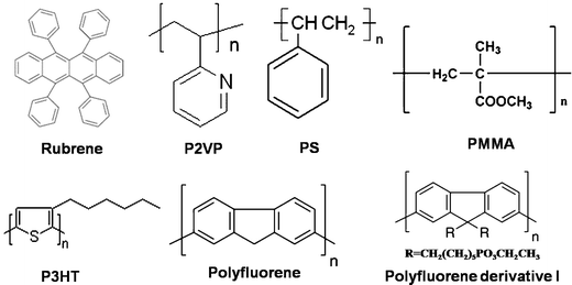
Rubrene with a purity greater than 99% was purchased from Sigma-Aldrich. PS with a molecular weight (Mw) of 2.020, 213.6 and 1.3 kDa were purchased from Sigma-Aldrich. PMMA (Mw = 102.6 kDa), poly(2-vinylpyridine) (P2VP, Mw = 143 kDa), poly(3-hexylthiophene-2,5-diyl) (P3HT, Mw = 68 kDa), polyfluorene (Mw = 89 kDa) and its derivative I (Mw = 105 kDa) (Scheme 1) were purchased from Sigma-Aldrich Co. Chlorobenzene (CB, 99%), toluene (99%), chloroform (99%), tetrahydrofuran (THF, 99%), carbon disulfide (CS2, 99%), dichloromethane (99%), methanol (99%) and acetone (99%) were purchased from Beijing Chemical, China. All the materials were used as received.Film preparation
Rubrene was dissolved in chloroform (CHCl3) with a concentration of 0.5% by weight. The polymers (PS, PMMA, P3HT, P2VP, polyfluorene and its derivative I) were dissolved in CHCl3 with a concentration of 0.5% and the solutions were stored overnight before use. Rubrene/polymer solutions were obtained by blending the individual solution with a varying ratio of polymer. For the rubrene/PS system, the percentages of PS in the total solute by weight were 10, 17, 30, 50, 65 and 85%, respectively. For other rubrene/polymer systems, the percentages of polymers were kept at 17%. The films were fabricated by spin-coating the blend solutions on glasses or silicon wafers for 30 s at a rate of 1250 rpm.Substrate preparation
The glass and silicon wafer substrates were cleaned in a piranha solution (70![[thin space (1/6-em)]](https://www.rsc.org/images/entities/char_2009.gif) :
:![[thin space (1/6-em)]](https://www.rsc.org/images/entities/char_2009.gif) 30 v/v of concentrated H2SO4 and 30% H2O2) at 90 °C for 20 min, then thoroughly rinsed with deionized water, and finally blown dry under nitrogen.
30 v/v of concentrated H2SO4 and 30% H2O2) at 90 °C for 20 min, then thoroughly rinsed with deionized water, and finally blown dry under nitrogen.
SVA procedure
A homemade setup used for the solvent vapour annealing procedure was shown in Fig. 1. For this setup, the solvent vapour pressure P could be calculated approximately by P = L/L0, where L is the distance from the up-edge of the setup to the specimen position and L0 is the length from the up-edge of the setup to the surface of the solvent at the bottom of the tube. The saturated vapour pressure of the corresponding solvent is labeled as 1. Before the SVA procedure, a volume of solvent was poured into the setup and the setup was sealed for 12 h to gain a stable vapour pressure distribution. The spin-coated film was then fixed on a holder and placed in an atmosphere of solvent vapour. The position of the holder could be moved to control the vapour pressure where the sample was placed. During the SVA process, the setup was sealed to ensure the constant solvent vapour pressure. The whole annealing procedure was performed for 12 h to achieve the complete crystallization of rubrene. All the operations were performed at room temperature.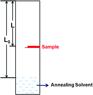 | ||
| Fig. 1 The schematic setup used in the solvent vapor annealing procedure. | ||
Crystallizing kinetic study
In the crystallizing kinetic study, rubrene/polymer film was placed in an atmosphere of CS2 vapor. The whole setup was placed under a polarized optical microscope. The morphology evolution was recorded automatically by taking the images of the films every 4 s.Characterization
Polarized optical microscopy (POM), atomic force microscopy (AFM), transmission electron microscopy (TEM), selected area electron diffraction (SAED) and grazing incidence X-ray diffraction (GIXD) were performed to characterize the morphologies and the crystalline structures of rubrene/polymer films.Both the ex situ and in situ POM images were taken with a polarized optical microscope (Zeiss Axio Imager A2m, Carl Zeiss, Germany) in reflection mode through two crossed polarizers. The AFM images were obtained using a SPA-300HV instrument with a SPI3800N Controller (Seiko Instruments Inc., Japan) in tapping mode. A silicon microcantilevel (spring constant 2 N m−1 and resonant frequency ≈ 70 kHz, Olympus, Japan) was used for the scanning. TEM images and SAED patterns were obtained with a JEOL JEM-1011 transmission electron microscope operated at an accelerating voltage of 100 kV. For TEM characterization, the film was floated from the glass substrate with deionized water and picked up with a copper grid. GIXD patterns were obtained on a Bruker D8 Discover Reflector (k = 1.78897 Å, Co source) under 40 kV and 40 mA tube current. The X-ray profile was recorded from 2 to 35° in steps of 0.05° using automatic slits.
3. Results and discussion
In the following part, firstly, rubrene spherulites obtained by solvent vapor annealing rubrene/polymer films will be demonstrated. Various factors including the content and molecular weight of the blended polymer, the annealing solvent and the solvent vapor pressure influence the formation of the spherulites. They will be discussed in detail. After that, the crystalline structures and kinetics of rubrene spherulites will be depicted. At last, the possible mechanism for the formation of rubrene spherulites will be proposed.3.1 The influence of the content and molecular weight of PS on the formation of rubrene spherulites
Rubrene spherulites have been fabricated by vacuum deposition,19 which is costly and requires complicated manipulation. Here we have obtained rubrene spherulites via a simple solution-process. By blending an amount of polymer into rubrene, the solution-processability of rubrene was realized easily by spin-coating. The amorphous films were then converted to spherulites after post-annealing in solvent vapor atmospheres.In order to confirm the universality of the SVA method to fabricate rubrene spherulites, we chose various types of polymer to blend into rubrene. The polymers we chose included flexible (such as PS, P2VP and PMMA) and conjugated polymers (such as P3HT, polyfluorene and its derivative I), the chemical structures of which were listed in Scheme 1. The Maltese crosses in Fig. 2, which were imaged with optical microscopy through crossed polarizers, indicated the formation of rubrene spherulites after annealing rubrene/polymer films in the vapors of dichloromethane and carbon disulfide. GIXD data of the spherulites were also shown in Fig. 2, which demonstrated the spherulites obtained for different rubrene/polymer films adopted the same crystal system. We chose the rubrene/PS system as an example to demonstrate the influence of the content and molecular weight of the polymer on the formation of rubrene spherulites in detail.
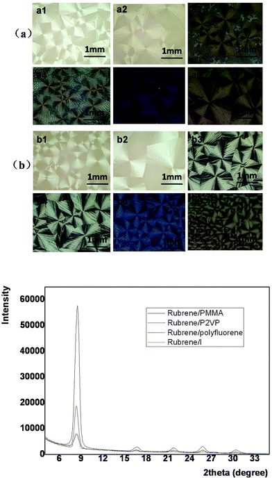 | ||
| Fig. 2 POM images of different rubrene/polymer films (17% polymer) after annealing in (a) CH2Cl2 and (b) CS2 vapors for 12 h, respectively. The vapor pressure was kept as P = 0.50 for both solvents. The blend films are (a1, b1) rubrene/polyfluorene, (a2, b2) rubrene/polyfluorene derivative I, (a3, b3) rubrene/P2VP, (a4, b4) rubrene/PMMA, (a5, b5) rubrene/P3HT and (a6, b6) rubrene/PS. GIXD result is also shown. | ||
From Fig. 3, we could see that rubrene spherulites were obtained after the SVA processes in dichloromethane vapor for rubrene/PS films with 10–50% PS. No spherulites were obtained when the ratio of PS exceeded 65%, which indicated that PS had a depressive effect on the formation of rubrene spherulites. When the ratio of PS was even higher (85%), no crystalline structures were obtained after the SVA process. The formation of sparse dendrites (65% PS) may be attributed to the hindering effect of the polymer matrix on the diffusion of rubrene molecules. When more PS molecules existed in the blend, the polymer matrix formed a barrier between the crystal nuclei and rubrene molecules. As a result, only the molecules near the nuclei could migrate to the crystal fronts and sparse crystals rather than dense rubrene spherulites were produced.
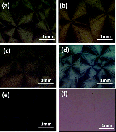 | ||
| Fig. 3 POM images of rubrene/PS films with different PS ratios after being annealed in CH2Cl2 vapor for 12 h. PS ratios are (a) 10, (b) 17, (c) 30, (d) 50, (e) 65 and (f) 85%, respectively. | ||
To explore the influence of the molecular weight of PS on the crystallization of rubrene, PS of varying molecular weights (Mw = 2020, 213.6, and 1.3 kDa) were blended into rubrene.
From the features shown in Fig. 4, we could see that at high solvent vapor pressure (P = 0.91), dewetting phenomenon took place for the rubrene/PS films containing PS with lower molecular weights (Mw = 1.3 or 213.6 kDa). Sparse crystals were obtained only on certain parts of the substrates. When PS of a high molecular weight (Mw = 2020 kDa) was blended into rubrene, denser dendrites could be observed. At low vapor pressure (P = 0.50), rubrene spherulites could only be obtained for the films containing PS with a higher molecular weight (Mw = 213.6 or 2020 kDa). However, the film containing PS with a low molecular weight (Mw = 1.3 kDa) fractured and no spherulites were observed.
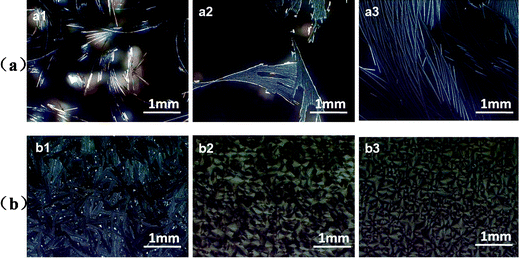 | ||
| Fig. 4 POM images of rubrene/PS films (17% PS) containing PS with different molecular weights after annealed in CS2 vapor for 12 h. The vapor pressures are (a) 0.91 and (b) 0.50, respectively. The molecular weights of PS are (a1, b1) Mw = 1.3 kDa, (a2, b2) Mw = 213.6 kDa and (a3, b3) Mw = 2020 kDa, respectively. | ||
We have stated that the characters of the solid films play an important role in the formation of rubrene spherulites. As PS with lower molecular weights (Mw = 213.6 or 1.3 kDa) had lower viscosities, the blended films often had weak mechanical strength, and consequently, the dewetting phenomenon easily took place at high vapor pressure (P = 0.91). For rubrene/PS film containing PS with a molecular weight of 1.3 kDa, no continuous crystals were observed even at low vapor pressure (P = 0.50). We can speculate that the molecular weight of blended PS must be large enough to ensure good mechanical character of the blended film for the formation of rubrene spherulites in the solvent vapor atmosphere.
3.2 The influence of the annealing solvent and solvent vapor pressure on the formation of rubrene spherulites
The annealing solvents had a significant influence on the crystallization of rubrene. In this work, several kinds of solvents were chosen, the physical parameters of which were listed in Table 1. The weight ratio of PS in the blend was fixed to 17% in each sample. The vapor pressures were adjusted precisely to fabricate rubrene spherulites. As it can be seen in Fig. 5, when dichloromethane and carbon disulfide were used as annealing solvents, nearly perfect rubrene spherulites were observed, as proved by the Maltese crosses imaged by optical microscopy through crossed polarizers. However, imperfect rubrene spherulites were obtained in the vapors of toluene and chlorobenzene, and annealing in the vapors of acetone and methanol resulted in only discrete crystals. It was noteworthy that the dewetting phenomenon took place when rubrene/PS films were annealing in the atmospheres of THF and chloroform.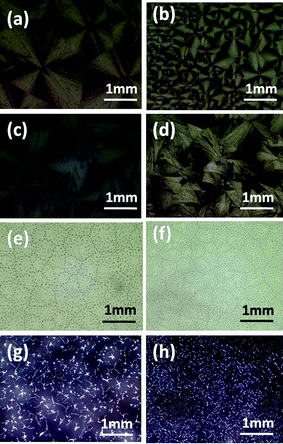 | ||
| Fig. 5 POM images of rubrene/PS films (17% PS) after annealed in (a) CH2Cl2, (b) CS2, (c) toluene, (d) chlorobenzene, (e) chloroform, (f) THF, (g) methanol and (h) acetone vapors for 12 h, respectively. | ||
| Solvent | CH2Cl2 | CS2 | CHCl3 | Toluene | CB | Acetone | Methanol | THF |
|---|---|---|---|---|---|---|---|---|
| Solubility (mg ml−1) | ∼ 10 | ∼ 10 | ∼ 15 | ∼ 14 | ∼ 10 | < 0.2 | < 0.2 | < 4 |
| Boiling point (°C) | 39.73 | 46.5 | 61.15 | 110.6 | 131.69 | 56.12 | 64.51 | 66 |
We attributed the formation of continuous rubrene spherulites to the sufficient migration ability of rubrene molecules towards the existing crystal nuclei. Dichloromethane, carbon disulfide, toluene and chlorobenzene are all good solvents of rubrene, but their boiling points differ sharply. Dichloromethane and carbon disulfide, having lower boiling points (i.e. higher vapor pressures) could easily penetrate into the films during the SVA procedure, and the dense solvent molecules provided sufficient mobility for rubrene molecules to migrate to the crystal nuclei. As a result, perfect rubrene spherulites could be fabricated. However, toluene and chlorobenzene have higher boiling points, which restrict the penetrability of the solvent molecules into the films. The existence of less solvent molecules made it hard for rubrene molecules to move to the crystal fronts. On the other hand, acetone and methanol are both poor solvents of rubrene. Few rubrene molecules could dissolve in the vapors, so they could not provide enough mobility for rubrene in the SVA process although their boiling points (56.12 and 64.51 °C) are only a little higher than that of dichloromethane and carbon disulfide. The poor mobility of rubrene molecules resulted in poor crystalline morphologies. As for the cases of chloroform and THF, we attributed the dewetting phenomenon to the strong affinity between the solvent molecules and the substrates. As the substrates we used here were glasses and silicon wafers, which were hydrophilic, the more polar solvents (chloroform and THF) with low boiling points may easily penetrate into the films and interact strongly with the substrates, resulting in dewetting of the films.
Here we have proved that only by annealing in the good solvents of rubrene with low boiling points, could we obtain rubrene spherulites for the rubrene/PS films. We propose that the migration force supplied to the rubrene molecules by the solvent molecules plays a key role in the formation of rubrene spherulites.
The solvent vapor pressures where the samples were placed had significant influence on the crystalline morphologies of rubrene in the SVA procedures. As can be seen in Fig. 6, where carbon disulfide was used as the annealing solvent, the morphologies of the rubrene crystals changed from discrete dendrites to dense spherulites as the solvent vapor pressure decreased gradually. It is worth mentioning that the dimensions of the rubrene spherulites could be adjusted by controlling the vapor pressures of the annealing solvent. As the solvent vapor pressures decreased, the density of spherulites increased and the diameters of the rubrene spherulites reduced. This phenomenon was in agreement with the report20 by E. Crossland et al. in which controllable P3HT spherulites were prepared by adjusting the solvent vapor pressure of the atmosphere. Nucleation density was proposed to explain the change of spherulites dimensions. Higher vapor pressure resulted in low nucleation density and thus larger spherulites, and vice versa. In our work, the vapor pressure of the atmosphere must be low enough to allow a high nucleation density for the formation of the rubrene spherulites. Higher vapor pressure often resulted in the formation of dendrites because of the low nucleation density, which we did not anticipate.
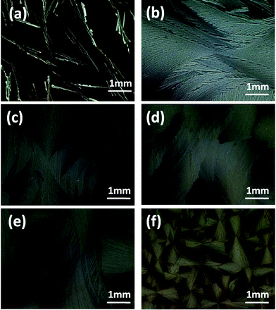 | ||
| Fig. 6 POM images of rubrene/PS (17% PS) films after annealing in CS2 vapor for 12 h. The vapor pressures are (a) 0.95, (b) 0.87, (c) 0.80, (d) 0.70, (e) 0.60 and (f) 0.50, respectively. | ||
3.3 Structural characterization of rubrene spherulites
To describe the microscale structures and electronic characters of rubrene spherulites, GIXD, AFM, TEM and SAED were performed.Until now, three crystal systems (monoclinic, triclinic and orthorhombic) of rubrene have been reported, 21,22 and the lattice parameters of these are listed in Table 2. GIXD was first carried out to confirm the crystal system which rubrene spherulites belonged to. The result was shown in Fig. 7a. For the spherulites obtained by annealing rubrene/PS film in carbon disulfide vapor, the sole strong peak at 2θ = 8.35° corresponded to an interplanar distance of 11.85 Å, which was accordant to the c-axis of the triclinic crystal. We attributed the peak to the (001) diffraction of the rubrene crystal. Other weak diffraction peaks corresponded to the (00n) diffraction of the crystal, where n = 2, 3, 4. We can thus conclude that the spherulites obtained through our SVA process belong to triclinic crystal system, and the crystals arrange with the c-axis perpendicular to the substrates.
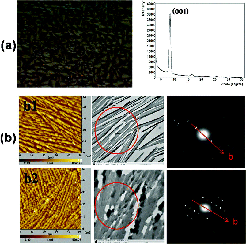 | ||
| Fig. 7 GIXD, AFM, TEM and SAED characterizations of rubrene spherulites. (a) GIXD result for the spherulites obtained by annealing rubrene/PS (17% PS) film in CS2 vapor for 12 h. The left picture is the corresponding POM images. (b) AFM, TEM images and SAED patterns of rubrene spherulites fabricated by annealing in (b1) CH2Cl2 and (b2) CS2 vapors for 12 h, respectively. The red circles indicate the selected zones for SAED characterization. | ||
| Crystal system | a (Å) | b (Å) | c (Å) | α (°) | β (°) | γ (°) | V (Å3) |
|---|---|---|---|---|---|---|---|
| Monoclinic | 8.7397(17) | 10.125(2) | 15.635(3) | 90 | 90.98(3) | 90 | 1383.3(5) |
| Triclinic | 7.0196(14) | 8.5432(17) | 11.948(2) | 93.04(3) | 105.58(3) | 96.28(3) | 683.5(2) |
| Orthorhombic | 26.775(4) | 7.1680(10) | 14.258(2) | 90 | 90 | 90 | 2736.4(7) |
From the AFM and bright field TEM images, we could see that rubrene spherulites were made up of a large number of smaller crystals with dimensions of a few micrometers. The crystals were well oriented in a small region, as revealed in the TEM images and SAED patterns. For the spherulites prepared by annealing rubrene/PS films in dichloromethane and carbon disulfide, ordered diffractive patterns were observed. Comparing the distances calculated from the SAED patterns to the lattice parameters listed in Table 2, the b-axis could be confirmed, and is denoted in Fig. 7b by red arrows. As the c-axis of the crystals was confirmed to be perpendicular to the substrates, we could conclude that the preferential growth direction of the spherulites was nearly parallel with the a-axis of the rubrene crystals, which was the largest π–π stacking direction for triclinic crystals.
As rubrene spherulites were well-oriented in microscale, we could anticipate the potential application of the polycrystalline films in the field of OTFT. As the spherulites grew along the a-axis, a better π–π stacking direction with the smallest lattice parameter and a high carrier mobility along the crystals in microscale could be expected. However, we should mention that the connectivity of rubrene crystals was not good enough. An interval was visible between the neighboring small crystals, which may restrict the macroscopic charge transport, thus resulting in lower carrier mobility of the rubrene spherulites.
3.4 The growth kinetics of rubrene spherulites
The growth kinetics of rubrene spherulites was studied for the rubrene/PS (Mw = 2020 kDa) blend by in situ observation of the growth of the spherulites by polarized optical microscopy. The morphologies of the rubrene spherulites at different stages of the SVA process were shown in Fig. 8a. The Maltese crosses imaged through crossed polarizers indicated the formation of rubrene spherulites. The diameters of the spherulites were summed in Table 3a. For the annealed rubrene/PS film, the diameters of rubrene spherulites increased from 305 to 1586 μm in 216 s. The increase in diameter was so fast that we decided that the SVA method for the formation of rubrene spherulites could be further applied. The plot in Fig. 8a shows that the growth rate of rubrene spherulites has an approximate linear dependence on the square root of the annealing time (t1/2). It can be indicated that the growth of the rubrene spherulites is diffusion-controlled,9 in which the diffusion of rubrene molecules to the crystal front is the limiting step of the crystallizing process.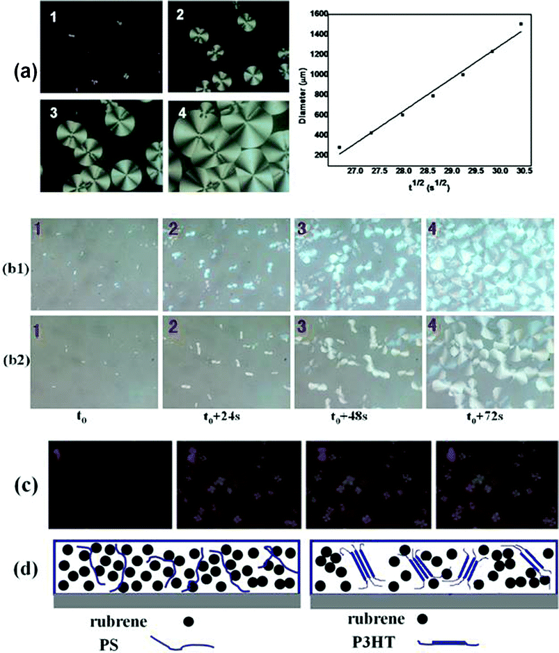 | ||
| Fig. 8 (a) Growth kinetics of rubrene spherulites when rubrene/PS film was annealed in CS2 vapor. PS (Mw = 2020 kDa) ratio is 17% by weight. 1–4 (1 = t0, 2 = t0 + 144 s, 3 = t0 + 216 s, 4 = t0 + 324 s; t0 = 12 min) represent the POM images of rubrene spherulites developing at different stages. The plot of rubrene spherulites diameter versus the square root of annealing time (t1/2) is also shown. (b) A comparison of growth kinetics of rubrene spherulites for rubrene/PS (17% PS) films containing PS with different molecular weights. The molecular weights of PS are (b1) Mw = 213.6 kDa and (b2) Mw = 2020 kDa, respectively. (c) POM images of rubrene spherulites developing at different stages (1 = t0, 2 = t0 + 144 s, 3 = t0 + 216 s, 4 = t0 + 324 s; t0 = 12 min) for rubrene/P3HT film (17% P3HT) annealing in CS2 vapor. (d) Schematic diagrams of rubrene and polymer molecules distribution in the blends (rubrene/PS and rubrene/P3HT system). | ||
In addition, we performed in situ experiments of the growth of rubrene spherulites for the blended films containing PS with different molecular weights (Mw = 213.6 or 2020 kDa), as shown in Fig. 8b. The vapor pressures were kept constant by pouring a fixed amount of solvent (carbon disulfide) into the same vessel. Almost the same growth rate was observed for both films, even though the molecular weight of PS differed by one order of magnitude. It may be argued that the molecular weight of PS plays a minor role in the crystallizing kinetics of rubrene spherulites. As an amorphous polymer, the matrix of PS in the blend is depicted in Fig. 8d. The flexibility of the PS molecule results in a weak hindering effect on the diffusion of the rubrene molecules, even when the molecular weight of PS is ultra-high (Mw = 2020 kDa).
To further explore the effect of blended polymers on the crystallization of rubrene, the crystallizing kinetics of rubrene spherulites were also studied for the rubrene/P3HT (semi-crystalline polymer) blend. The experimental conditions (weight ratio of polymer molecule and solvent vapor pressure) were kept the same as in the rubrene/PS system. The morphologies of the rubrene spherulites at different stages of the SVA process are shown in Fig. 8c, and the diameters of the spherulites are sumarized in Table 3b. Compared to the rubrene/PS system, we could see that the growth rate of rubrene spherulites was much slower for rubrene/semi-crystallizing polymer system. We can thus conclude that the semi-crystallizing polymer has a much more remarkable depressive effect on the crystallization of rubrene than the amorphous polymer. As a semi-crystalline polymer, P3HT is partly ordered in the blend film (Fig. 8d). It is hard for rubrene molecules to diffuse through the P3HT matrix due to its rigid structure. Consequently, the growth velocity of the rubrene spherulites depends significantly on the type of polymer blended into the rubrene.
3.5 The mechanism of the formation of rubrene spherulites
Solvent vapor annealing has been widely used23–29 to obtain ordered microscale and nanoscale structures for organic materials, such as discotic molecules. The mechanism of the SVA process has been proposed below: the solvent molecules penetrate into the organic films because of evaporation, then the solid films are partly dissolved and the organic molecules can migrate, which self-assemble into ordered structures. In this work, the introduction of a polymer made the case more complicated.Firstly, in order to study the status of polymer molecules in the blended films during the SVA procedure, plasticization was introduced. The effect of plasticization on Tg can be estimated based on the equation30 below:
 | (1) |
Rubrene is a conjugated molecule having a tetracene backbone substituted by four phenyls, which disturbs the co-plane structure and thus hampers free crystallization. However, based on the crystallizing kinetics, large rubrene spherulites could cover the substrate completely in less than 10 min for the rubrene/PS film annealing in carbon disulfide vapor. We could thus confirm that the solvent molecules played a key role in the formation of rubrene spherulites. On the other hand, PS must have a depressive effect on the crystallization of rubrene, which has been discussed earlier, as no spherulites could be obtained by the SVA process with a high PS ratio.
We proposed here a mechanism for the formation of rubrene spherulites. The competitive relation between the impetus of the annealing solvent vapor and the impeditive force of the blended polymer on the diffusion of rubrene molecules must be responsible for the ultimate crystal morphology. In the presence of a PS matrix, the solvent molecules were first absorbed into the film, and rubrene molecules were then reorganized as a result of the increasing mobility because of its high solubility in the annealing solvent. After the formation of the initial crystal nuclei, rubrene molecules had to traverse the PS matrix and diffuse to the crystal fronts. Perfect spherulites were obtained when rubrene molecules had enough mobility to break the depressing effect of PS molecules. This is why rubrene spherulites could only be obtained by annealing the blend films in solvents with low boiling points and high solubility for rubrene (dichloromethane and carbon disulfide).
Based on reports in the literature, there are two main categories of spherulites.31 For type I spherulites, the crystals grow radially from the initial nucleation site, branching gradually to maintain a space filling character. In contrast, for type II spherulites, the crystals grow initially as threadlike fibers, which form new grains at the growth front. This branching of the crystallizing pattern ultimately leads to a crystal “sheaf”. After that, these sheaves develop two “eyes” on each side of the initial nucleation sites. Ultimately, the crystals settle down into a spherical growth pattern, with “eye” structures apparent in its core region. From the morphology and crystallizing kinetics of rubrene spherulites, we can see that the spherulites belong to type I, which show an approximate circlular shape and indicate radial growth of the crystals. As can be seen in Fig. 9, a model was proposed to depict the growth of rubrene spherulites. In the SVA procedure, the solvent molecules partly dissolve rubrene molecules and lead to the formation of the initial nuclei based on the migration of rubrene. As the crystals grow, secondary nuclei appear from the pre-existing crystals. The rather low vapor pressure (P < 0.50) results in large nuclear density, which induces the radial growth of the crystals. In the same manner, rubrene spherulites form at last. The model is accordant with the in situ observation of the growth of rubrene spherulites.
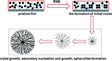 | ||
| Fig. 9 Schematic representation of the growth of rubrene spherulites. In the first stage, initial nuclei appear because of the aggregation of rubrene molecules promoted by the impetus of solvent molecules. Then secondary nuclei develop accompanying the growth of the existed crystals. The rather large nuclei density resulting from the lower vapor pressure induces the radiative growth of the crystals. In this manner, rubrene spherulites of type I emerge at last. | ||
4. Conclusions
In summary, an amount of polymer was blended into rubrene to achieve solution-processability. Rubrene spherulites were obtained when rubrene/polymer films were annealed in atmospheres of CH2Cl2 and CS2. Only when a polymer with a high molecular weight was blended could rubrene spherulites form. The depressive effect of the polymer matrix on the crystallization of rubrene was elucidated. The decrease of solvent vapor pressure resulted in a crystallizing morphological transition from dendrites to spherulites, which we attributed to the increase in crystal nuclei density. The spherulites adopted a triclinic system with the c-axis perpendicular to the substrate. The formation mechanism of rubrene spherulites was proposed as the competition between the impetus of the solvent vapor and the impeditive force of polymer matrix on the diffusion of rubrene molecules. As the branches of the spherulites are large enough to cover the channel of an OTFT device, we believe that the polycrystalline films can be further applied.Acknowledgements
This work was financially supported by the National Natural Science Foundation of China (20621401, 20834005, 51073151) and National Basic Research Program of China (973 Program-2009CB930603).References
- S. H. Liu, W. C. M. Wang, A. L. Briseno, S. C. E. Mannsfeld and Z. N. Bao, Adv. Mater., 2009, 21, 1217–1232 CrossRef CAS.
- E. Menard, V. Podzorov, S. H. Hur, A. Gaur, M. E. Gershenson and A. Rogers, Adv. Mater., 2004, 16, 2097–2101 CrossRef CAS.
- V. C. Sundar, J. Zaumseil, V. Podzorov, E. Menard, R. L. Willett, T. Someya, M. E. Gershenson and J. A. Rogers, Science, 2004, 303, 1644–1646 CrossRef CAS.
- H. Najafov, B. Lee, Q. Zhou, L. C. Feldman and V. Podzorov, Nat. Mater., 2010, 9, 938–943 CrossRef CAS.
- V. Podzorov, S. E. Sysoev, E. Loginova, V. M. Pudalov and M. E. Gershenson, Appl. Phys. Lett., 2003, 83, 3504–3506 CrossRef CAS.
- D. Käfer and G. Witte, Phys. Chem. Chem. Phys., 2005, 7, 2850–2853 RSC.
- L. W. Huang, Q. Liao ;, Q. Shi, H. B. Fu, J. S. Ma and J. N. Yao, J. Mater. Chem., 2010, 20, 159–166 RSC.
- T. Matsukawa, M. Yoshimura, K. Sasai, M. Uchiyama, M. Yamagishi, Y. Tominari, Y. Takahashi, J. Takeya, Y. Kitaoka, Y. Mori and T. Sasaki, J. Cryst. Growth, 2010, 312, 310–313 CrossRef CAS.
- T. Matsukawa, Y. Takahashi, T. Tokiyama, K. Sasai, Y. Murai, N. Hirota, Y. Tominari, N. Mino, M. Yoshimura, M. ABE, J. Takeya, Y. Kitaoka, Y. Mori, S. Morita and T. Sasaki, Jpn. J. Appl. Phys., 2008, 47, 8950–8954 CrossRef CAS.
- S. Park, J. Choi, K. Lee, H. Yeom and S. Im, J. Phys. Chem. B, 2010, 114, 5661–5665 CrossRef CAS.
- D. H. Park, S. G. Jo, Y. K. Hong, C. Z. Cui, H. Lee, D. J. Ahn, J. Kim and J. Joo, J. Mater. Chem., 2011, 21, 8002–8007 RSC.
- J. Smith, R. Hamilton, I. McCulloch, N. Stingelin-Stutzmann, M. Heeney, D. D. C. Bradleya and T. D. Anthopoulos, J. Mater. Chem., 2010, 20, 2562–2574 RSC.
- D. M. Russell, C. J. Newsome, S. P. Li, T. Kugler and M. Ishida, Appl. Phys. Lett., 2005, 87, 222109 CrossRef.
- W. Lee, J. A. Lim, D. Kwak, J. H. Cho, H. S. Lee, H. H. Choi and K. Cho, Adv. Mater., 2009, 21, 4243–4248 CrossRef CAS.
- T. Ohe, M. Kuribayashi, A. Tsuboi, K. Satori, M. Itabashi and K. Nomoto, Appl. Phys. Express, 2009, 2, 121502 CrossRef.
- J. Kang, N. Shin, D. Y. Jang, V. M. Prabhu and D. Y. Yoon, J. Am. Chem. Soc., 2008, 130, 12273–12275 CrossRef CAS.
- M. Madec, D. Crouch, G. R. Llorente, T. J. Whittle, M. Geogheganc and S. G. Yeates, J. Mater. Chem., 2008, 18, 3230–3236 RSC.
- N. Stingelin-Stutzmann, E. Smith, H. Wondergem, C. Tanase, P. Blom, P. Smith and D. De Leeuw, Nat. Mater., 2005, 4, 601–606 CrossRef CAS.
- Y. Luo, M. Brun, P. Rannou and B. Grevin, Phys. Status Solidi A, 2007, 204, 1851–1855 CrossRef CAS.
- E. J. W. Crossland, K. Rahimi, G. Reiter, U. Steiner and S. Ludwigs, Adv. Funct. Mater., 2011, 3, 518–524 CrossRef.
- O. D. Jurchescu, A. Meetsma and T. T. M. Palstra, Acta Crystallogr., Sect. B: Struct. Sci., 2006, 62, 330 Search PubMed.
- (a) W. H. Taylor, Z. Kristallogr., 1936, 93, 151 CAS; (b) Z. A. Akopyan, R. L. Avoyan and Y. T. Struchkov, Z. Strukt. Khim., 1962, 3, 602 CAS.
- A. Datar, R. Oitker and L. Zang, Chem. Commun., 2006, 1649–1651 Search PubMed.
- J. W. Chung, B. K. An, F. Hirato, J. H. Kim, H. Jinnai and S. Y. Park, J. Mater. Chem., 2010, 20, 7715–7720 RSC.
- G. D. Luca, A. Liscio, F. Nolde, L. M. Scolaro, V. Palermo, K. Müllen and P. Samori, Soft Matter, 2008, 4, 2064–2070 RSC.
- C. Liu, T. Minari, X. Lu, A. Kumatani, K. Takimiya and K. Tsukagoshi, Adv. Mater., 2011, 23, 523–526 CrossRef CAS.
- K. C. Dickey, J. E. Anthony and Y. L. Loo, Adv. Mater., 2006, 18, 1721–1726 CrossRef CAS.
- G. D. Luca, A. Liscio, P. Maccagnani, F. Nolde, V. Palermo, K. Müllen and P. Samori, Adv. Funct. Mater., 2007, 17, 3791–3798 CrossRef.
- E. Treossi, A. Liscio, X. Feng, V. Palermo, K. Müllen and P. Samori, Small, 2009, 5, 112–119 CrossRef CAS.
- D. J. Mascaro, M. E. Thompson, H. I. Smith and V. Bulović, Org. Electron., 2005, 6, 211–220 CrossRef CAS.
- L. Gránásy, T. Pusztai, G. Tegze, J. A. Warren and J. F. Douglas, Phys. Rev. E: Stat., Nonlinear, Soft Matter Phys., 2005, 72, 011605 CrossRef.
| This journal is © The Royal Society of Chemistry 2012 |

